EP0309552B1 - Integrated cascade refrigeration system - Google Patents
Integrated cascade refrigeration system Download PDFInfo
- Publication number
- EP0309552B1 EP0309552B1 EP88903716A EP88903716A EP0309552B1 EP 0309552 B1 EP0309552 B1 EP 0309552B1 EP 88903716 A EP88903716 A EP 88903716A EP 88903716 A EP88903716 A EP 88903716A EP 0309552 B1 EP0309552 B1 EP 0309552B1
- Authority
- EP
- European Patent Office
- Prior art keywords
- circuit
- compression
- absorption
- refrigeration
- refrigerant
- Prior art date
- Legal status (The legal status is an assumption and is not a legal conclusion. Google has not performed a legal analysis and makes no representation as to the accuracy of the status listed.)
- Expired - Lifetime
Links
- 238000005057 refrigeration Methods 0.000 title claims abstract description 48
- QGZKDVFQNNGYKY-UHFFFAOYSA-N Ammonia Chemical compound N QGZKDVFQNNGYKY-UHFFFAOYSA-N 0.000 claims abstract description 63
- 230000006835 compression Effects 0.000 claims abstract description 54
- 238000007906 compression Methods 0.000 claims abstract description 54
- 238000010521 absorption reaction Methods 0.000 claims abstract description 47
- 229910021529 ammonia Inorganic materials 0.000 claims abstract description 29
- 239000003507 refrigerant Substances 0.000 claims description 55
- 238000001816 cooling Methods 0.000 claims description 18
- 239000007788 liquid Substances 0.000 claims description 17
- 230000002745 absorbent Effects 0.000 claims description 13
- 239000002250 absorbent Substances 0.000 claims description 13
- 238000009434 installation Methods 0.000 claims description 12
- 238000001704 evaporation Methods 0.000 claims description 8
- 238000010438 heat treatment Methods 0.000 claims description 8
- 239000002826 coolant Substances 0.000 claims description 6
- 230000005611 electricity Effects 0.000 claims description 5
- 230000008020 evaporation Effects 0.000 claims description 4
- 150000008282 halocarbons Chemical group 0.000 claims description 3
- 230000020169 heat generation Effects 0.000 claims description 2
- 238000010248 power generation Methods 0.000 claims description 2
- 238000009420 retrofitting Methods 0.000 abstract description 2
- 230000000717 retained effect Effects 0.000 abstract 1
- 239000002918 waste heat Substances 0.000 abstract 1
- XLYOFNOQVPJJNP-UHFFFAOYSA-N water Substances O XLYOFNOQVPJJNP-UHFFFAOYSA-N 0.000 description 21
- 239000006096 absorbing agent Substances 0.000 description 11
- 239000007789 gas Substances 0.000 description 8
- 239000000243 solution Substances 0.000 description 8
- 238000000034 method Methods 0.000 description 5
- 238000010992 reflux Methods 0.000 description 4
- 230000008569 process Effects 0.000 description 3
- VHUUQVKOLVNVRT-UHFFFAOYSA-N Ammonium hydroxide Chemical compound [NH4+].[OH-] VHUUQVKOLVNVRT-UHFFFAOYSA-N 0.000 description 2
- 238000004378 air conditioning Methods 0.000 description 2
- 235000011114 ammonium hydroxide Nutrition 0.000 description 2
- AMXOYNBUYSYVKV-UHFFFAOYSA-M lithium bromide Chemical compound [Li+].[Br-] AMXOYNBUYSYVKV-UHFFFAOYSA-M 0.000 description 2
- 230000004048 modification Effects 0.000 description 2
- 238000012986 modification Methods 0.000 description 2
- 230000009467 reduction Effects 0.000 description 2
- 230000008439 repair process Effects 0.000 description 2
- 230000000153 supplemental effect Effects 0.000 description 2
- 230000008901 benefit Effects 0.000 description 1
- 239000012267 brine Substances 0.000 description 1
- 239000000498 cooling water Substances 0.000 description 1
- 230000008878 coupling Effects 0.000 description 1
- 238000010168 coupling process Methods 0.000 description 1
- 238000005859 coupling reaction Methods 0.000 description 1
- 238000010586 diagram Methods 0.000 description 1
- 230000000694 effects Effects 0.000 description 1
- 239000006193 liquid solution Substances 0.000 description 1
- 239000010687 lubricating oil Substances 0.000 description 1
- 230000014759 maintenance of location Effects 0.000 description 1
- 238000004519 manufacturing process Methods 0.000 description 1
- 231100000252 nontoxic Toxicity 0.000 description 1
- 230000003000 nontoxic effect Effects 0.000 description 1
- HPALAKNZSZLMCH-UHFFFAOYSA-M sodium;chloride;hydrate Chemical compound O.[Na+].[Cl-] HPALAKNZSZLMCH-UHFFFAOYSA-M 0.000 description 1
Images


Classifications
-
- F—MECHANICAL ENGINEERING; LIGHTING; HEATING; WEAPONS; BLASTING
- F25—REFRIGERATION OR COOLING; COMBINED HEATING AND REFRIGERATION SYSTEMS; HEAT PUMP SYSTEMS; MANUFACTURE OR STORAGE OF ICE; LIQUEFACTION SOLIDIFICATION OF GASES
- F25B—REFRIGERATION MACHINES, PLANTS OR SYSTEMS; COMBINED HEATING AND REFRIGERATION SYSTEMS; HEAT PUMP SYSTEMS
- F25B25/00—Machines, plants or systems, using a combination of modes of operation covered by two or more of the groups F25B1/00 - F25B23/00
- F25B25/02—Compression-sorption machines, plants, or systems
Definitions
- This invention relates to refrigeration systems.
- a refrigerant such as Freon or ammonia may initially be in the liquid state, under pressure. It is then passed through an expansion valve where it evaporates and becomes a gas with a very substantial drop in temperature. Air is normally blown past coils or pipes through which the evaporating refrigerant is flowing, and the cold air cools the refrigerator or the home. The warmed gas is then routed to an electric compressor, which further heats the gas as it is compressed. The hot compressed gas is then routed to a cooling tower or condenser, where the compressed refrigerant reverts to the liquid state as it is cooled. The cooling cycle is then repeated.
- Freon or ammonia may initially be in the liquid state, under pressure. It is then passed through an expansion valve where it evaporates and becomes a gas with a very substantial drop in temperature. Air is normally blown past coils or pipes through which the evaporating refrigerant is flowing, and the cold air cools the refrigerator or the home. The warmed gas is then routed to an electric compressor, which further heat
- Absorption system refrigeration circuits are somewhat more complicated. They use a refrigerant such as ammonia, and an absorbent, such as water. As in the compression circuit described above, cooling is accomplished when the liquid refrigerant goes through an exparsion valve and is permitted to evaporate, with the expected substantial reduction in temperature, and is used for cooling. The vaporized refrigerant, which has now increased in temperature, then flows to an absorber where it is restored to liquid form by being dissolved in the liquid absorbent, such as water, with the substantial generation of heat, normally removed by cooling water or air when water is not available.
- a refrigerant such as ammonia
- an absorbent such as water
- the liquid solution of absorbent and refrigerant are then raised to a high pressure by a pump, and routed to a still, or other arrangements such as a reboiler and fractionating column combination, wherein external heating is supplied to separate the ammonia (refrigerant) from the water (absorbent).
- the hot gaseous ammonia at relatively high pressure is then routed to a condenser where it is cooled and liquefied. The cycle is then repeated.
- U.S. Patent No. 4,565,069 discloses an air conditioning system which utilises separate absorption and compression circuits to cool a secondary exchange, brine filled, circuit.
- the compressor of the compression circuit is powered by electricity supplied from a generator, excess heat from the generator being used in the absorption circuit heat pump system. It is also known to condense the refrigerant used in one circuit by the evaporation of the refrigerant used in a second circuit.
- a principal object of the present invention is to provide an improved refrigeration system which is substantially more efficient than existing systems.
- a refrigeration system for cooling a space comprising a compression refrigeration circuit, including an evaporator for providing the refrigeration for the space and a compressor, an absorption refrigeration circuit, including means for separating absorption circuit refrigerant from absorbent, means for generating power including heat, means for supplying heat from the power generating means to said absorption circuit separating means, and means for supplying power from said power generating means to power the compressor in said compression refrigeration circuit, characterised by heat exchange means for cooling and condensing the refrigerant used in said compression circuit by the evaporation of the refrigerant in said absorption circuit, the system thus being operable as a self-modulating system wherein increased cooling demand causes increased power generation for driving said compressor, and thus increased heat generation to boost the absorption circuit capacity.
- the absorption circuit is coupled to the compression circuit at a heat exchanger wherein the hot compressed gaseous refrigerant in the compression cycle is cooled, and the liquid combination of the absorbent and refrigerant is heated, preparatory to separating the refrigerant from the absorbent.
- Two reboilers may be provided, with the hot exhaust gases from the engine of the engine-generator being directed to a high temperature reboiler, and heated coolant from the engine being directed to a lower temperature reboiler.
- Embodiments of the invention may be designed to be readily retrofitted onto existing compression systems, whether Freon, ammonia, or other refrigerants are used, with the cost of the retrofit equipment being recovered in less than a year, in many cases, through savings in electric charges.
- the retrofit installation could still include the original compression circuit condenser or cooling unit, so that during repair or modification of the absorption circuit, the compression circuit could operate as a "stand-alone" refrigeration system.
- Embodiments may also supply electricity to operate additional equipment such as lights or the like, or could supply electricity to the local utility power net.
- the compression of the refrigerant in the compression circuit may be accomplished in two stages, with each circuit refrigerant being cooled by the evaporation of the absorption circuit refrigerant.
- An important advantage of certain embodiments of the present invention is the self-regulating or self-modulating nature of the system.
- the compressor will require more electric power, and the motor generator will run under increased load and will supply additional heat to the reboilers to process more of the absorption refrigerant.
- the cooling provided by the absorption circuit is increased, and the compression ratio is reduced. Accordingly, the entire system is automatically coordinated to provide a highly efficient cascade refrigeration system even under varying load conditions.
- Fig. 1 shows a comparatively simple version of the present invention suitable for retrofitting with respect to an existing refrigeration system.
- the system includes a prime mover 12, such as an engine or a turbine, and an associated electric generator 14 for supplying power to the pumps and for other functions as described hereinbelow.
- a compression circuit including the electric motor 16 and the associated compressor 18.
- the liquid compression refrigerant which may for example, be Freon
- the evaporator 24 is the point in the circuit where refrigeration occurs.
- the evaporator 24 would be located within a refrigerator or cold storage room. After the gaseous Freon has served its cooling function, and has increased somewhat in temperature, it is routed via line 26 to the compressor 18.
- the compressed gaseous refrigerant is then routed along the line 28 to the heat exchanger 30 in which the hot compressed Freon is cooled somewhat, and water having a strong concentration of ammonia, otherwise known as "strong aqua” is heated.
- strong aqua water having a strong concentration of ammonia, otherwise known as "strong aqua” is heated. The heating of the strong aqua or the Concentrated solution of separate ammonia gas from the water, is discussed below.
- the partially cooled Freon vapor is routed to the exchanger 32 which is the principal coupling link between the compression refrigeration circuit which appears to the left in Fig. 1, and the absorption refrigeration circuit which appears to the right in Fig. 1. More particularly, the unit 32 is the condenser for the compression circuit and is the evaporator for the absorption circuit. Thus, the liquid ammonia is permitted to expand at the expansion valve 34, and in the process of evaporating, cools and condenses the Freon.
- the unit 32 may include a cylindrical chamber with end caps as shown, and a series of pipes extending through the chamber 32 which are chilled as a result of carrying the ammonia at reduced pressure in the process of evaporating, with the Freon in the space within chamber 32 surrounding the chilled pipes.
- any suitable heat exchange method may be employed.
- the liquid Freon is returned to the expansion valve 22 over the line 20.
- an existing condenser 36 for a stand-alone compression refrigeration system is coupled by valve 38 to line 40 between the heat exchanger 30 and the unit 32.
- the appropriate valving is installed in line 28 and/or 40 which closes during evaporator defrost and allows high pressure gas to become available for this purpose.
- the valve 38 may be opened and condensed liquid Freon from the condenser 36 may be routed via line 42 to the expansion valve 22.
- suitable valving not shown in each case, may be provided to make the changeover, either automatically upon appropriate pressure or temperature changes, or manually.
- liquid ammonia is permitted to expand at the expansion valve 34, and it cools and condenses the Freon in the unit 32.
- the ammonia has been partially warmed as it leaves the unit 32, and is mixed with water and absorbed into the water in the mixer 46 and the absorber 48.
- the concentrated solution of ammonia otherwise known in the refrigeration field as "strong aqua” is routed from the absorber 48 to the surge tank 50, and is then pumped by the strong aqua pump 52 to the heat exchanger 30.
- strong aqua is routed from the absorber 48 to the surge tank 50, and is then pumped by the strong aqua pump 52 to the heat exchanger 30.
- the concentrated solution of water and ammonia is heated to some extent in the heat exchanger 30.
- the exchanger 54 in which the hot, relatively pure water from reboiler 56 serves to supply the heat.
- the strong aqua is routed to the reboiler 58 where it is further heated by the liquid coolant flowing through the lines 60 from the engine 12.
- the first reboiler 56 is heated directly by exhaust gases from the engine 12, as indicated by the line 64 at the lower right in Fig. 1.
- the reboiler 56 may require supplemental heating, and this may be accomplished electrically, as indicated by the dashed line 66 and the resistive element 68 shown within the reboiler 56.
- the combination of the two reboilers 56 and 58, in combination with the fractionating column 70 serve to separate the gaseous ammonia from water.
- the ammonia under high pressure is condensed in the unit 72 which is normally subject to either air or circulating water cooling.
- the reflux retention tank 74 permits the recirculation of a portion of the liquid ammonia through line 76 and the reflux valve 78 to the fractionating column 70.
- the liquid ammonia at high pressure is routed over line 80 to the expansion valve 34.
- the block 82 indicates collateral refrigeration or other equipment which may be operated from the electric power supplied on electric circuits 84 from the electric generator 14.
- the compressors and pumps may be mechanically coupled directly to the prime mover 12; however, normally separate electric motors are provided for driving this collateral equipment including compressors and pumps.
- Figure 2 shows an alternative embodiment of the invention primarily intended for large refrigeration installations.
- the compression circuit is shown mainly toward the top of the figure and to the right, while the absorption refrigeration circuit is shown principally toward the bottom of the figure and to the left.
- the system of Fig. 2 differs from that of Fig. 1 principally in the multiple staging of the system operation. This increases the efficiency, but is often not economically worthwhile unless substantial size systems are involved.
- the expansion valve for the compression circuit is located at reference numeral 102, and the compression circuit evaporator 104 is the place where cooling takes place.
- the evaporator 104 would be located within the refrigerated storage area which the system is designed to cool.
- the somewhat warmed low pressure gaseous refrigerant in line 106 from the evaporator 104 is routed to the heat exchanger 108 which serves much the same function as the unit 32 in Fig. 1. More specifically, the liquid absorption circuit refrigerant from the tank 110 is routed to the expansion valve 112, and the heat exchanger 108 serves to chill the refrigerant from the compressor circuit so that some portion of it condenses and is collected in the tank 114, while the bulk of the gaseous refrigerant is compressed in the compressor 116 which has a relatively low compression ratio.
- a second heat exchanger 118 is provided wherein the absorption circuit refrigerant is evaporating following expansion at the expansion valve 120 and the gaseous compression refrigerant is further cooled, with some additional portion of it being condensed and collected in the chamber 122.
- the remainder of the gaseous compression circuit refrigerant is routed to the compressor 124 which compresses and heats the refrigerant, and from which it is routed to the compression circuit high pressure condenser 126.
- the compression circuit refrigerant which may be Freon or ammonia, for examples, is then collected in the receiving tank 128.
- the conduit 130 from the receiver tank 128 completes the compression circuit path to the expansion valve 102.
- the pump 132 and the pump 134 serve to route the liquid refrigerant collected in tanks 114 and 122, respectively, to the conduit 130 which is already carrying liquid refrigerant.
- the compression circuit may be implemented without the use of the compressor 124, with a slight reduction in efficiency, but at lower capital outlay.
- the container 110 containing the liquid absorption circuit refrigerant which will usually be ammonia.
- the absorption circuit condenser 134 is normally cooled by water, where available, or otherwise by air, as discussed hereinabove for the unit 72 in the system of Fig. 1.
- a small portion of the ammonia is fed back to the fractionating column 136 from the reflux surge drum 138, with the recirculation being accomplished by the reflux pump 140.
- the fractionating column 136 Associated with the fractionating column 136 are the two reboilers 142 and 144 which receive heat from the prime mover 146 as described hereinabove relative to the engine 12 of Fig. 1.
- the output from unit 108 mentioned above is gaseous ammonia, and this output is routed to the low temperature absorber 152 along the line 154 from the condenser/evaporator unit 108; and to the medium temperature absorber 156 along line 158 from the condenser/evaporator 118.
- the highly concentrated ammonia-water solutions are routed to the evaporative coolers 158 and 160 by the pumps 162 and 164, respectively.
- the liquid is recirculated to the absorbers 152 and 156 to maintain the temperature of the absorbers at a reasonable level.
- the surge tanks 172 and 174, and the associated motors 176 and 178 are below the absorbers 152 and 156.
- the strong aqua from the surge tanks 174 and 176 are routed on lines 180 and 182 to the heat exchangers 184 and 186.
- the other input to these two heat exchangers is the hot water from the fractionating column 136 where the ammonia has been removed from the "strong aqua".
- the water, or "weak aqua” is cooled, and the “strong aqua", or concentrated ammonia-water solution, is heated, preparatory to application to the fractionating column where the solution must be very hot in order for the ammonia to be taken off from the water.
- the line 188 couples the water from the heat exchanger 184 to the absorber units.
- a heat exchanger such as the unit 30 shown in Fig. 1, wherein the "strong aqua” is heated and the Freon or other compression refrigerant is cooled, could also be used in the system of Fig. 2.
- supplemental electrical heating as indicated at 66, 68 in Fig. 1, could also be used in connection with the reboilers and fractionating column of Fig. 2.
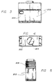
- Figures 3, 4 and 5 show external views of one illustrative embodiment of a retrofit installation.
- the unit 202 may be approximately 8 feet tall, 9 feet long, and 4 feet in depth to accommodate a unit providing approximately 20 tons of refrigeration, and 70 kilowatts of electrical output.
- the unit 202 may have a digital display 204, and may have a fan 206 at the top, and louvers 208 on the side to provide air circulation for cooling.
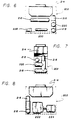
- Figures 6, 7 and 8 indicate schematically the location of units within the housing 202 of Figs. 3, 4 and 5.
- the combined evaporator for the absorption circuit and the condenser for the compression circuit is shown at reference numeral 212.
- the condenser and the absorber for the absorption circuit are shown as a single large unit 214 toward the top of the assemblage.
- the fractionating column 216 and the first and second reboilers 218 and 220 are located at one end of the unit, and the engine 222 and electric generator 224 are located along the back of the unit near the base thereof.
- the "strong aqua" pump, or the pump for the concentrated solution of water and ammonia is shown at reference numeral 228 adjacent the base of the unit.
- One or more heat exchangers may be located at reference numeral 230 as indicated in Fig. 6 of the drawings. In view of the fact that the installation as shown in Figs. 3 through 8 is intended for retrofit installations, no compression circuit compressor is shown in this unit.
- the motor generator may be either a stand-alone unit, or it may be coupled to the local utility electric power net. In the latter event, the motor generator is operated synchronously with the alternating current of the local utility, and the owner of the refrigeration system installation is given credit on his utility bill for electricity supplied to the local electrical net.
- ammonia is the preferred absorption circuit refrigerant, used with water as the absorbent, and ammonia could also be used as the compression circuit refrigerant.
- the absorption system could also use water as the refrigerant and lithium bromide as the absorbent.
- Various refrigerants are available under the tradename Freon, and they may be used as the compression refrigerant. Freon is a halocarbon, and is relatively stable, and non-toxic, so it is often used in preference to ammonia for nonindustrial refrigeration applications. Halocarbon refrigerants, similar to Freon are also available under other trade names.
- heat from the engine lubricating oil may be used for pre-heating the strong aqua, or for other heating purposes in the system or adjacent facilities.
- radiated heat from the engine may be recovered by a suitable heat exchange method in cooperation with the engine enclosure, or the unit enclosure as shown in Figs. 3 - 8. Accordingly, the present invention is not limited to the arrangements precisely as shown in the drawings, and described in the detailed description.
Landscapes
- Engineering & Computer Science (AREA)
- Physics & Mathematics (AREA)
- Mechanical Engineering (AREA)
- Thermal Sciences (AREA)
- General Engineering & Computer Science (AREA)
- Sorption Type Refrigeration Machines (AREA)
- Devices That Are Associated With Refrigeration Equipment (AREA)
- Compression-Type Refrigeration Machines With Reversible Cycles (AREA)
Abstract
Description
- This invention relates to refrigeration systems.
- There are two principal types of refrigeration systems generally in use, namely, compression refrigeration systems and absorption refrigeration systems.
- The most well-known refrigeration systems are the compression systems used in most home refrigerators and home air-conditioning systems. A refrigerant, such as Freon or ammonia may initially be in the liquid state, under pressure. It is then passed through an expansion valve where it evaporates and becomes a gas with a very substantial drop in temperature. Air is normally blown past coils or pipes through which the evaporating refrigerant is flowing, and the cold air cools the refrigerator or the home. The warmed gas is then routed to an electric compressor, which further heats the gas as it is compressed. The hot compressed gas is then routed to a cooling tower or condenser, where the compressed refrigerant reverts to the liquid state as it is cooled. The cooling cycle is then repeated.
- Absorption system refrigeration circuits are somewhat more complicated. They use a refrigerant such as ammonia, and an absorbent, such as water. As in the compression circuit described above, cooling is accomplished when the liquid refrigerant goes through an exparsion valve and is permitted to evaporate, with the expected substantial reduction in temperature, and is used for cooling. The vaporized refrigerant, which has now increased in temperature, then flows to an absorber where it is restored to liquid form by being dissolved in the liquid absorbent, such as water, with the substantial generation of heat, normally removed by cooling water or air when water is not available. The liquid solution of absorbent and refrigerant are then raised to a high pressure by a pump, and routed to a still, or other arrangements such as a reboiler and fractionating column combination, wherein external heating is supplied to separate the ammonia (refrigerant) from the water (absorbent). The hot gaseous ammonia at relatively high pressure is then routed to a condenser where it is cooled and liquefied. The cycle is then repeated.
- Normally power is supplied from commercial sources to power the pumps or compressors in refrigeration circuits. However, in some systems, such as that disclosed in U.S. Patent No. 4,335,580, heat from the coolant system of an engine is employed to at least heat the refrigerant when it is functioning in a reverse cycle in the "defrost" mode of the unit. Also, U.S. Patent No. 4,380,909 discloses the use of heat from engine exhaust gases in an absorption cycle heat pump system. Also to be noted are prior systems in which a single refrigerant is employed in both compression and absorption refrigeration modes, see U.S. Patent Nos. 4,505,133, 4,031,712, and 4,285,211.
- U.S. Patent No. 4,565,069 discloses an air conditioning system which utilises separate absorption and compression circuits to cool a secondary exchange, brine filled, circuit. The compressor of the compression circuit is powered by electricity supplied from a generator, excess heat from the generator being used in the absorption circuit heat pump system. It is also known to condense the refrigerant used in one circuit by the evaporation of the refrigerant used in a second circuit.
- However, the foregoing systems have significant problems, and substantially lower efficiency than would be desirable. In addition, it is not possible with Freon systems and not practical in most cases to retrofit existing refrigeration systems to conform with ammonia systems with the teachings of the foregoing cited patents.
- Accordingly, a principal object of the present invention is to provide an improved refrigeration system which is substantially more efficient than existing systems.
- According to the present invention, there is provided a refrigeration system for cooling a space and comprising a compression refrigeration circuit, including an evaporator for providing the refrigeration for the space and a compressor, an absorption refrigeration circuit, including means for separating absorption circuit refrigerant from absorbent, means for generating power including heat, means for supplying heat from the power generating means to said absorption circuit separating means, and means for supplying power from said power generating means to power the compressor in said compression refrigeration circuit,
characterised by heat exchange means for cooling and condensing the refrigerant used in said compression circuit by the evaporation of the refrigerant in said absorption circuit, the system thus being operable as a self-modulating system wherein increased cooling demand causes increased power generation for driving said compressor, and thus increased heat generation to boost the absorption circuit capacity. - The absorption circuit is coupled to the compression circuit at a heat exchanger wherein the hot compressed gaseous refrigerant in the compression cycle is cooled, and the liquid combination of the absorbent and refrigerant is heated, preparatory to separating the refrigerant from the absorbent.
- Two reboilers may be provided, with the hot exhaust gases from the engine of the engine-generator being directed to a high temperature reboiler, and heated coolant from the engine being directed to a lower temperature reboiler.
- Embodiments of the invention may be designed to be readily retrofitted onto existing compression systems, whether Freon, ammonia, or other refrigerants are used, with the cost of the retrofit equipment being recovered in less than a year, in many cases, through savings in electric charges. The retrofit installation could still include the original compression circuit condenser or cooling unit, so that during repair or modification of the absorption circuit, the compression circuit could operate as a "stand-alone" refrigeration system.
- Embodiments may also supply electricity to operate additional equipment such as lights or the like, or could supply electricity to the local utility power net.
- To further increase efficiency, with a relatively low additional capital investment, the compression of the refrigerant in the compression circuit may be accomplished in two stages, with each circuit refrigerant being cooled by the evaporation of the absorption circuit refrigerant.
- An important advantage of certain embodiments of the present invention is the self-regulating or self-modulating nature of the system. Thus, if additional cooling is required, the compressor will require more electric power, and the motor generator will run under increased load and will supply additional heat to the reboilers to process more of the absorption refrigerant. In turn, the cooling provided by the absorption circuit is increased, and the compression ratio is reduced. Accordingly, the entire system is automatically coordinated to provide a highly efficient cascade refrigeration system even under varying load conditions.
- For a better understanding of the invention and to show how the same may be carried into effect, reference will now be made, by way of example, to the accompanying drawings, wherein:
- Figure 1 is a schematic circuit diagram of a cascade refrigeration system illustrating the principles of the present invention;
- Figure 2 shows an alternative cascade refrigeration system illustrating the principles of the present invention which is intended for larger installations;
- Figures 3, 4 and 5 are different views of the basic configuration of a retrofit installation suitable for implementing the system of the present invention; and
- Figures 6, 7 and 8 are diagrammatic showings indicating the arrangement of the major components of the retrofit installation as shown in Figs. 3 through 5.
- Referring more particularly to the drawings, Fig. 1 shows a comparatively simple version of the present invention suitable for retrofitting with respect to an existing refrigeration system. More particularly, as shown in Fig. 1, the system includes a
prime mover 12, such as an engine or a turbine, and an associatedelectric generator 14 for supplying power to the pumps and for other functions as described hereinbelow. To the left in Fig. 1 is a compression circuit including theelectric motor 16 and the associatedcompressor 18. Incidentally, the liquid compression refrigerant, which may for example, be Freon, is routed on theline 20 to theexpansion valve 22, and theevaporator 24 is the point in the circuit where refrigeration occurs. Thus, theevaporator 24 would be located within a refrigerator or cold storage room. After the gaseous Freon has served its cooling function, and has increased somewhat in temperature, it is routed via line 26 to thecompressor 18. - The compressed gaseous refrigerant is then routed along the
line 28 to theheat exchanger 30 in which the hot compressed Freon is cooled somewhat, and water having a strong concentration of ammonia, otherwise known as "strong aqua" is heated. The heating of the strong aqua or the Concentrated solution of separate ammonia gas from the water, is discussed below. - From the
heat exchanger 30, the partially cooled Freon vapor is routed to theexchanger 32 which is the principal coupling link between the compression refrigeration circuit which appears to the left in Fig. 1, and the absorption refrigeration circuit which appears to the right in Fig. 1. More particularly, theunit 32 is the condenser for the compression circuit and is the evaporator for the absorption circuit. Thus, the liquid ammonia is permitted to expand at theexpansion valve 34, and in the process of evaporating, cools and condenses the Freon. Theunit 32 may include a cylindrical chamber with end caps as shown, and a series of pipes extending through thechamber 32 which are chilled as a result of carrying the ammonia at reduced pressure in the process of evaporating, with the Freon in the space withinchamber 32 surrounding the chilled pipes. However, any suitable heat exchange method may be employed. To complete the compression circuit, the liquid Freon is returned to theexpansion valve 22 over theline 20. - In the case of retrofit installations, an existing
condenser 36 for a stand-alone compression refrigeration system is coupled byvalve 38 toline 40 between theheat exchanger 30 and theunit 32. The appropriate valving is installed inline 28 and/or 40 which closes during evaporator defrost and allows high pressure gas to become available for this purpose. In the event of repair or modification of the absorption system which appears to the right in Fig. 1, thevalve 38 may be opened and condensed liquid Freon from thecondenser 36 may be routed vialine 42 to theexpansion valve 22. It is understood that suitable valving, not shown in each case, may be provided to make the changeover, either automatically upon appropriate pressure or temperature changes, or manually. - Referring now to the absorption system, it has previously been noted that liquid ammonia is permitted to expand at the
expansion valve 34, and it cools and condenses the Freon in theunit 32. The ammonia has been partially warmed as it leaves theunit 32, and is mixed with water and absorbed into the water in themixer 46 and theabsorber 48. The concentrated solution of ammonia, otherwise known in the refrigeration field as "strong aqua", is routed from theabsorber 48 to thesurge tank 50, and is then pumped by thestrong aqua pump 52 to theheat exchanger 30. As mentioned above, the concentrated solution of water and ammonia is heated to some extent in theheat exchanger 30. - It is heated further in the
exchanger 54 in which the hot, relatively pure water fromreboiler 56 serves to supply the heat. From theheat exchanger 54, the strong aqua is routed to thereboiler 58 where it is further heated by the liquid coolant flowing through thelines 60 from theengine 12. Incidentally, thefirst reboiler 56 is heated directly by exhaust gases from theengine 12, as indicated by theline 64 at the lower right in Fig. 1. In some cases, thereboiler 56 may require supplemental heating, and this may be accomplished electrically, as indicated by the dashedline 66 and theresistive element 68 shown within thereboiler 56. - The combination of the two reboilers 56 and 58, in combination with the
fractionating column 70 serve to separate the gaseous ammonia from water. The ammonia under high pressure is condensed in theunit 72 which is normally subject to either air or circulating water cooling. Thereflux retention tank 74 permits the recirculation of a portion of the liquid ammonia throughline 76 and thereflux valve 78 to thefractionating column 70. As previously mentioned, the liquid ammonia at high pressure is routed overline 80 to theexpansion valve 34. - The
block 82 indicates collateral refrigeration or other equipment which may be operated from the electric power supplied onelectric circuits 84 from theelectric generator 14. Incidentally, if desired, or if convenient from an installation standpoint, the compressors and pumps may be mechanically coupled directly to theprime mover 12; however, normally separate electric motors are provided for driving this collateral equipment including compressors and pumps. - Figure 2 shows an alternative embodiment of the invention primarily intended for large refrigeration installations. In Fig. 2, the compression circuit is shown mainly toward the top of the figure and to the right, while the absorption refrigeration circuit is shown principally toward the bottom of the figure and to the left. In general, the system of Fig. 2 differs from that of Fig. 1 principally in the multiple staging of the system operation. This increases the efficiency, but is often not economically worthwhile unless substantial size systems are involved.
- Referring now to the details of the refrigeration system of Fig. 2, the expansion valve for the compression circuit is located at
reference numeral 102, and thecompression circuit evaporator 104 is the place where cooling takes place. Thus, theevaporator 104 would be located within the refrigerated storage area which the system is designed to cool. - The somewhat warmed low pressure gaseous refrigerant in line 106 from the
evaporator 104 is routed to theheat exchanger 108 which serves much the same function as theunit 32 in Fig. 1. More specifically, the liquid absorption circuit refrigerant from thetank 110 is routed to theexpansion valve 112, and theheat exchanger 108 serves to chill the refrigerant from the compressor circuit so that some portion of it condenses and is collected in thetank 114, while the bulk of the gaseous refrigerant is compressed in thecompressor 116 which has a relatively low compression ratio. Asecond heat exchanger 118 is provided wherein the absorption circuit refrigerant is evaporating following expansion at theexpansion valve 120 and the gaseous compression refrigerant is further cooled, with some additional portion of it being condensed and collected in thechamber 122. The remainder of the gaseous compression circuit refrigerant is routed to thecompressor 124 which compresses and heats the refrigerant, and from which it is routed to the compression circuithigh pressure condenser 126. The compression circuit refrigerant, which may be Freon or ammonia, for examples, is then collected in the receivingtank 128. Theconduit 130 from thereceiver tank 128 completes the compression circuit path to theexpansion valve 102. Incidentally, thepump 132 and thepump 134 serve to route the liquid refrigerant collected intanks conduit 130 which is already carrying liquid refrigerant. - Incidentally, the compression circuit may be implemented without the use of the
compressor 124, with a slight reduction in efficiency, but at lower capital outlay. - Turning now to the absorption circuit, we have noted the
container 110 containing the liquid absorption circuit refrigerant, which will usually be ammonia. Theabsorption circuit condenser 134 is normally cooled by water, where available, or otherwise by air, as discussed hereinabove for theunit 72 in the system of Fig. 1. A small portion of the ammonia is fed back to thefractionating column 136 from thereflux surge drum 138, with the recirculation being accomplished by thereflux pump 140. Associated with thefractionating column 136 are the tworeboilers prime mover 146 as described hereinabove relative to theengine 12 of Fig. 1. - Turning now to the absorption refrigeration circuit, the output from
unit 108 mentioned above, is gaseous ammonia, and this output is routed to thelow temperature absorber 152 along theline 154 from the condenser/evaporator unit 108; and to themedium temperature absorber 156 alongline 158 from the condenser/evaporator 118. Following absorption of the gaseous ammonia by the water and the resultant significant increase in the temperature of the solution, the highly concentrated ammonia-water solutions are routed to theevaporative coolers pumps evaporative coolers absorbers absorbers surge tanks motors 176 and 178, respectively. Now, the strong aqua from thesurge tanks lines 180 and 182 to theheat exchangers fractionating column 136 where the ammonia has been removed from the "strong aqua". In theheat exchangers line 188 couples the water from theheat exchanger 184 to the absorber units. - Incidentally, some of the additional features shown in Fig. 1 may also be included in the system of Fig. 2. Thus, for example, a heat exchanger such as the
unit 30 shown in Fig. 1, wherein the "strong aqua" is heated and the Freon or other compression refrigerant is cooled, could also be used in the system of Fig. 2. Similarly, supplemental electrical heating as indicated at 66, 68 in Fig. 1, could also be used in connection with the reboilers and fractionating column of Fig. 2. - Figures 3, 4 and 5 show external views of one illustrative embodiment of a retrofit installation. In Fig. 3, the
unit 202 may be approximately 8 feet tall, 9 feet long, and 4 feet in depth to accommodate a unit providing approximately 20 tons of refrigeration, and 70 kilowatts of electrical output. Theunit 202 may have adigital display 204, and may have afan 206 at the top, andlouvers 208 on the side to provide air circulation for cooling. - Figures 6, 7 and 8 indicate schematically the location of units within the
housing 202 of Figs. 3, 4 and 5. In Figs. 6, 7 and 8, the combined evaporator for the absorption circuit and the condenser for the compression circuit is shown atreference numeral 212. The condenser and the absorber for the absorption circuit are shown as a singlelarge unit 214 toward the top of the assemblage. Thefractionating column 216 and the first and second reboilers 218 and 220 are located at one end of the unit, and theengine 222 andelectric generator 224 are located along the back of the unit near the base thereof. The "strong aqua" pump, or the pump for the concentrated solution of water and ammonia is shown atreference numeral 228 adjacent the base of the unit. One or more heat exchangers may be located atreference numeral 230 as indicated in Fig. 6 of the drawings. In view of the fact that the installation as shown in Figs. 3 through 8 is intended for retrofit installations, no compression circuit compressor is shown in this unit. - Incidentally, the units included in the present disclosure and particularly in the drawings, have been shown schematically, as virtually all of these units are well-known, per se. Manufacturers who produce components as noted hereinbelow, are listed in the following table:
Compressors: Vilter Manufacturing Corp. Milwaukee, Wisconsin. Condensers and evaporative coolers: Baltimore Air Coil Company, Inc., Baltimore, Maryland. Heat exchangers, Reboilers, and Surge tanks: Thermal Finned Processors, Los Angeles, California. Fractionating columns, Absorbers, and Reboilers: Kotch Engineering Co., Inc. Witchita, Kansas. Evaporators: Krack Corp., Addison, Illinois. Pumps: Viking Pump Division, Houdaille Industries, Inc., Cedar Falls, Iowa. Engine-generators: Waukesha Power Systems, Waukesha, Wisconsin - Incidentally, the motor generator may be either a stand-alone unit, or it may be coupled to the local utility electric power net. In the latter event, the motor generator is operated synchronously with the alternating current of the local utility, and the owner of the refrigeration system installation is given credit on his utility bill for electricity supplied to the local electrical net.
- Concerning refrigerants, ammonia is the preferred absorption circuit refrigerant, used with water as the absorbent, and ammonia could also be used as the compression circuit refrigerant. The absorption system could also use water as the refrigerant and lithium bromide as the absorbent. Various refrigerants are available under the tradename Freon, and they may be used as the compression refrigerant. Freon is a halocarbon, and is relatively stable, and non-toxic, so it is often used in preference to ammonia for nonindustrial refrigeration applications. Halocarbon refrigerants, similar to Freon are also available under other trade names.
- In conclusion, it is to be understood that the foregoing description relates to preferred embodiments illustrating the principles of the invention. Although the invention has been described primarily on the basis of using Freon as the compressible refrigerant and ammonia as the absorbent refrigerant, other refrigerants known in the art may be employed both for the compression circuit and also for the absorbent circuit. In addition, other known types of components may be employed to implement the various components of the system. Thus, instead of the fractionating column and reboilers, various forms of stills may be used. In addition, staging may be employed to increase efficiency, at slightly increased capital cost, with the use of two or three stages for the various refrigeration steps serving to increase efficiency but at slightly increased cost. Concerning another point, heat from the engine lubricating oil may be used for pre-heating the strong aqua, or for other heating purposes in the system or adjacent facilities. Similarly, radiated heat from the engine may be recovered by a suitable heat exchange method in cooperation with the engine enclosure, or the unit enclosure as shown in Figs. 3 - 8. Accordingly, the present invention is not limited to the arrangements precisely as shown in the drawings, and described in the detailed description.
Claims (13)
- A refrigeration system for cooling a space and comprising a compression refrigeration circuit, including an evaporator (24) for providing the refrigeration for the space and a compressor (18), an absorption refrigeration circuit, including means (56) for separating absorption circuit refrigerant from absorbent, means (12, 14) for generating power including heat, means (64) for supplying heat from the power generating means to said absorption circuit separating means (56), and means for supplying power from said power generating means to power said compressor (18) in said compression refrigeration circuit,
characterised by heat exchange means (32) for cooling and condensing the refrigerant used in said compression circuit by the evaporation of the refrigerant in said absorption circuit, the system thus being operable as a self-modulating system wherein increased cooling demand causes increased power generation for driving said compressor (18), and thus increased heat generation to boost the absorption circuit capacity. - A system as defined in claim 1 wherein ammonia is employed as the refrigerant in the absorption circuit.
- A system as defined in claim 1 or 2 wherein the compression circuit refrigerant is ammonia.
- A system as defined in claim 1 or 2 wherein the refrigerant in the compression circuit is a halocarbon such as Freon.
- A system as defined in any one of the preceding claims, and including means (68) for electrically heating the means (56) for separating the absorption circuit refrigerant and absorbent.
- A system as defined in any one of the preceding claims, wherein said compression circuit includes a multistage compression circuit.
- A system as defined in any one of the preceding claims, and comprising condenser means (36) for operating said compression circuit independently of said absorption circuit, and means (38) for switching from cascade operation, wherein said absorption circuit is operative, to a simple compression circuit mode of operation.
- A system as defined in any one of the preceding claims wherein the generating means comprises a prime mover (12).
- A system as defined in claim 8, wherein said prime mover has a hot gas exhaust (64) and heated liquid coolant, and wherein means are provided for heating the absorption circuit separating means (56) from both said hot gas exhaust and said heated liquid coolant.
- A system as defined in claim 9, wherein said separating means (56) includes a fractionating column (70) and first and second associated reboilers, with the gas exhaust being coupled to a first one (56) of said reboilers and said coolant being coupled to the second reboiler (58).
- A system as defined in any one of the preceding claims wherein said power is electrical power.
- A system as defined in claim 11 and comprising means (84) for supplying electricity from the generating means to circuits other than said refrigeration circuits.
- A system as defined in any one of the preceding claims and comprising means for mounting said absorption refrigeration circuit, said generating means, said heat supplying means and said heat exchange means (32) as a single physical assembly for use in a retrofit installation with an existing compression refrigeration system.
Priority Applications (1)
| Application Number | Priority Date | Filing Date | Title |
|---|---|---|---|
| AT88903716T ATE100926T1 (en) | 1987-04-09 | 1988-04-08 | INTEGRATED CASCADES COOLING SYSTEM. |
Applications Claiming Priority (2)
| Application Number | Priority Date | Filing Date | Title |
|---|---|---|---|
| US36711 | 1987-04-09 | ||
| US07/036,711 US4819445A (en) | 1987-04-09 | 1987-04-09 | Integrated cascade refrigeration system |
Publications (3)
| Publication Number | Publication Date |
|---|---|
| EP0309552A1 EP0309552A1 (en) | 1989-04-05 |
| EP0309552A4 EP0309552A4 (en) | 1991-11-21 |
| EP0309552B1 true EP0309552B1 (en) | 1994-01-26 |
Family
ID=21890176
Family Applications (1)
| Application Number | Title | Priority Date | Filing Date |
|---|---|---|---|
| EP88903716A Expired - Lifetime EP0309552B1 (en) | 1987-04-09 | 1988-04-08 | Integrated cascade refrigeration system |
Country Status (7)
| Country | Link |
|---|---|
| US (1) | US4819445A (en) |
| EP (1) | EP0309552B1 (en) |
| JP (1) | JPH01503324A (en) |
| AU (1) | AU592742B2 (en) |
| CA (1) | CA1289371C (en) |
| DE (1) | DE3887421T2 (en) |
| WO (1) | WO1988008107A1 (en) |
Families Citing this family (9)
| Publication number | Priority date | Publication date | Assignee | Title |
|---|---|---|---|---|
| JP2996518B2 (en) * | 1991-02-13 | 2000-01-11 | 株式会社日立製作所 | Heat storage type air conditioning equipment and air conditioning method |
| US5163302A (en) * | 1991-10-21 | 1992-11-17 | General Motors Corporation | Air conditioning system with precooler |
| ES2582941T3 (en) * | 2004-11-15 | 2016-09-16 | Mayekawa Mfg. Co., Ltd. | Method and device for liquefaction and cryogenic refrigeration |
| US8555911B2 (en) * | 2007-08-24 | 2013-10-15 | Howard Heil | Method and apparatus for water surge protection |
| RU2360189C1 (en) * | 2007-12-26 | 2009-06-27 | ГОУ ВПО "Южно-Российский государственный университет экономики и сервиса" (ЮРГУЭС) | Test-bench for testing absorption-compression aggregate |
| EP2405083A1 (en) * | 2010-07-07 | 2012-01-11 | Johannus Leonardus Elsinghorst | Inflatable hall and method for controlling the pressure and/or the temperature therein |
| ES2579204B1 (en) * | 2015-02-06 | 2017-06-26 | Universidade Da Coruña | Compression and absorption combined cycle refrigeration plant partially fed with residual heat from the alternative mechanical compressor |
| AU2015415452B2 (en) | 2015-11-26 | 2021-12-02 | Dometic Sweden Ab | Hybrid cooling appliance |
| IL254616B (en) * | 2017-09-24 | 2020-01-30 | N A M Tech Ltd | Combined-type cascade refrigerating apparatus |
Family Cites Families (18)
| Publication number | Priority date | Publication date | Assignee | Title |
|---|---|---|---|---|
| US2274152A (en) * | 1937-07-16 | 1942-02-24 | Honeywell Regulator Co | Air conditioning system |
| US2260477A (en) * | 1938-09-24 | 1941-10-28 | Honeywell Regulator Co | Air conditioning system |
| US2385033A (en) * | 1941-09-20 | 1945-09-18 | Henry G Schwarz | Refrigeration unit for internalcombustion engines |
| US2388210A (en) * | 1943-04-23 | 1945-10-30 | B F Sturtevant Co | Refrigeration system for air-conditioned passenger vehicles |
| DE953378C (en) * | 1950-08-29 | 1956-11-29 | Margarete Altenkirch Geb Schae | Method and device for operating a heat pump |
| US3015940A (en) * | 1954-07-26 | 1962-01-09 | Harwich Stanley | Refrigerative compression system driven by fluid energy of an absorption system |
| US3401530A (en) * | 1966-12-19 | 1968-09-17 | Lithonia Lighting Inc | Comfort conditioning system |
| US3824804A (en) * | 1973-08-22 | 1974-07-23 | C Sandmark | Refrigerating machines |
| CA1011958A (en) * | 1973-10-13 | 1977-06-14 | Friedrich Knopsmeier | Refrigeration method and apparatus |
| JPS5121414U (en) * | 1974-08-05 | 1976-02-17 | ||
| FR2309806A1 (en) * | 1974-12-20 | 1976-11-26 | Chausson Usines Sa | Heat pump air conditioning system - has cooling circuit of engine driving first pump connected to second pump |
| US4374468A (en) * | 1980-03-18 | 1983-02-22 | Matsushita Electric Industrial Company | Absorption type refrigeration system including compressor driven auxiliary flow circuits isolated from main circuit |
| JPS57192762A (en) * | 1981-05-22 | 1982-11-26 | Nisshin Kogyo Kk | Cryogenic two-dimensional refrigeration method and its device |
| US4380909A (en) * | 1981-07-17 | 1983-04-26 | Chevron Research Company | Method and apparatus for co-generation of electrical power and absorption-type heat pump air conditioning |
| JPS5899661A (en) * | 1981-12-09 | 1983-06-14 | トヨタ自動車株式会社 | Engine waste-heat recovery absorption type cold and hot water machine |
| JPS58129172A (en) * | 1982-01-29 | 1983-08-02 | 株式会社日立製作所 | cooling equipment |
| JPS5912843A (en) * | 1982-07-14 | 1984-01-23 | 日新製鋼株式会社 | Weldable composite coated steel plate |
| US4565069A (en) * | 1984-11-05 | 1986-01-21 | Maccracken Calvin D | Method of cyclic air conditioning with cogeneration of ice |
-
1987
- 1987-04-09 US US07/036,711 patent/US4819445A/en not_active Ceased
-
1988
- 1988-03-21 CA CA000561953A patent/CA1289371C/en not_active Expired
- 1988-04-08 AU AU16224/88A patent/AU592742B2/en not_active Ceased
- 1988-04-08 DE DE88903716T patent/DE3887421T2/en not_active Expired - Fee Related
- 1988-04-08 EP EP88903716A patent/EP0309552B1/en not_active Expired - Lifetime
- 1988-04-08 JP JP63503588A patent/JPH01503324A/en active Pending
- 1988-04-08 WO PCT/US1988/001134 patent/WO1988008107A1/en not_active Ceased
Non-Patent Citations (1)
| Title |
|---|
| Cube, Lehrbuch der Kältetechnik, C.F.Müller 1981, pages 199,200 * |
Also Published As
| Publication number | Publication date |
|---|---|
| DE3887421D1 (en) | 1994-03-10 |
| US4819445A (en) | 1989-04-11 |
| AU592742B2 (en) | 1990-01-18 |
| JPH01503324A (en) | 1989-11-09 |
| CA1289371C (en) | 1991-09-24 |
| DE3887421T2 (en) | 1994-05-11 |
| EP0309552A4 (en) | 1991-11-21 |
| AU1622488A (en) | 1988-11-04 |
| EP0309552A1 (en) | 1989-04-05 |
| WO1988008107A1 (en) | 1988-10-20 |
Similar Documents
| Publication | Publication Date | Title |
|---|---|---|
| US3675441A (en) | Two stage refrigeration plant having a plurality of first stage refrigeration systems | |
| EP2019272B1 (en) | Combined receiver and heat exchanger for a secondary refrigerant | |
| US20020033024A1 (en) | Utilization of harvest and/or melt water from an ice machine for a refrigerant subcool/precool system and method therefor | |
| US4869069A (en) | Integrated cascade refrigeration system | |
| MXPA01011080A (en) | Outdoor heat exchanger unit, outdoor unit, and gas heat pump type air conditioner. | |
| US20120017621A1 (en) | Cooling method and apparatus | |
| US4949547A (en) | Method of and apparatus for air-conditioning individual spaces | |
| EP0309552B1 (en) | Integrated cascade refrigeration system | |
| US5579652A (en) | Generator-absorber-heat exchange heat transfer apparatus and method and use thereof in a heat pump | |
| USRE34030E (en) | Integrated cascade refrigeration system | |
| US5782097A (en) | Generator-absorber-heat exchange heat transfer apparatus and method and use thereof in a heat pump | |
| EP0739471B1 (en) | Generator-absorber heat exchange heat transfer apparatus and method using an intermediate liquor and use thereof in an absorption heat pump | |
| JP2005331147A (en) | Power generating and air-conditioning system | |
| EP2856042B1 (en) | Energy recovery apparatus | |
| JP3918980B2 (en) | Refrigeration equipment | |
| JPS6294415A (en) | Cooler for vehicle | |
| JP3871206B2 (en) | Refrigeration system combining absorption and compression | |
| KR200328870Y1 (en) | High Efficiency Air Heating and Cooling Apparatus Combined Engine Heat Pump with Heat of Earth | |
| JPS6158745B2 (en) | ||
| JPH0733932B2 (en) | Helium compressor for cryocoolers | |
| JPH08136082A (en) | Cold water production system | |
| MXPA96001470A (en) | Heat transfer appliance through heat extraction between generator-absorbing and method and using it in an ac pump | |
| MXPA98009021A (en) | Method and apparatus of heat transfer, exchange of heat of generator-absorbing and use of delmism in a thermal pump | |
| JP2000283593A (en) | Combined cooling system and combined cooling method | |
| JPH05133639A (en) | Refrigerating plant |
Legal Events
| Date | Code | Title | Description |
|---|---|---|---|
| PUAI | Public reference made under article 153(3) epc to a published international application that has entered the european phase |
Free format text: ORIGINAL CODE: 0009012 |
|
| 17P | Request for examination filed |
Effective date: 19881209 |
|
| AK | Designated contracting states |
Kind code of ref document: A1 Designated state(s): AT BE CH DE FR GB IT LI NL SE |
|
| A4 | Supplementary search report drawn up and despatched |
Effective date: 19911003 |
|
| AK | Designated contracting states |
Kind code of ref document: A4 Designated state(s): AT BE CH DE FR GB IT LI NL SE |
|
| 17Q | First examination report despatched |
Effective date: 19920306 |
|
| RAP1 | Party data changed (applicant data changed or rights of an application transferred) |
Owner name: SCHERER, FRANK J. Owner name: SCHERER, JOHN STIRLING |
|
| GRAA | (expected) grant |
Free format text: ORIGINAL CODE: 0009210 |
|
| AK | Designated contracting states |
Kind code of ref document: B1 Designated state(s): AT BE CH DE FR GB IT LI NL SE |
|
| PG25 | Lapsed in a contracting state [announced via postgrant information from national office to epo] |
Ref country code: SE Effective date: 19940126 Ref country code: LI Effective date: 19940126 Ref country code: CH Effective date: 19940126 Ref country code: BE Effective date: 19940126 Ref country code: AT Effective date: 19940126 |
|
| REF | Corresponds to: |
Ref document number: 100926 Country of ref document: AT Date of ref document: 19940215 Kind code of ref document: T |
|
| ITF | It: translation for a ep patent filed | ||
| ET | Fr: translation filed | ||
| REF | Corresponds to: |
Ref document number: 3887421 Country of ref document: DE Date of ref document: 19940310 |
|
| REG | Reference to a national code |
Ref country code: CH Ref legal event code: PL |
|
| PLBE | No opposition filed within time limit |
Free format text: ORIGINAL CODE: 0009261 |
|
| STAA | Information on the status of an ep patent application or granted ep patent |
Free format text: STATUS: NO OPPOSITION FILED WITHIN TIME LIMIT |
|
| 26N | No opposition filed | ||
| PGFP | Annual fee paid to national office [announced via postgrant information from national office to epo] |
Ref country code: FR Payment date: 19980930 Year of fee payment: 11 |
|
| PGFP | Annual fee paid to national office [announced via postgrant information from national office to epo] |
Ref country code: DE Payment date: 19981002 Year of fee payment: 11 |
|
| PGFP | Annual fee paid to national office [announced via postgrant information from national office to epo] |
Ref country code: GB Payment date: 19981006 Year of fee payment: 11 |
|
| PGFP | Annual fee paid to national office [announced via postgrant information from national office to epo] |
Ref country code: NL Payment date: 19981020 Year of fee payment: 11 |
|
| PG25 | Lapsed in a contracting state [announced via postgrant information from national office to epo] |
Ref country code: GB Free format text: LAPSE BECAUSE OF NON-PAYMENT OF DUE FEES Effective date: 19990408 |
|
| PG25 | Lapsed in a contracting state [announced via postgrant information from national office to epo] |
Ref country code: NL Free format text: LAPSE BECAUSE OF NON-PAYMENT OF DUE FEES Effective date: 19991101 |
|
| GBPC | Gb: european patent ceased through non-payment of renewal fee |
Effective date: 19990408 |
|
| PG25 | Lapsed in a contracting state [announced via postgrant information from national office to epo] |
Ref country code: FR Free format text: LAPSE BECAUSE OF NON-PAYMENT OF DUE FEES Effective date: 19991231 |
|
| NLV4 | Nl: lapsed or anulled due to non-payment of the annual fee |
Effective date: 19991101 |
|
| REG | Reference to a national code |
Ref country code: FR Ref legal event code: ST |
|
| PG25 | Lapsed in a contracting state [announced via postgrant information from national office to epo] |
Ref country code: DE Free format text: LAPSE BECAUSE OF NON-PAYMENT OF DUE FEES Effective date: 20000201 |
|
| PG25 | Lapsed in a contracting state [announced via postgrant information from national office to epo] |
Ref country code: IT Free format text: LAPSE BECAUSE OF NON-PAYMENT OF DUE FEES Effective date: 20050408 |