EP0308639A2 - Gefäss zum Aufbewahren von flüssigem Helium - Google Patents
Gefäss zum Aufbewahren von flüssigem Helium Download PDFInfo
- Publication number
- EP0308639A2 EP0308639A2 EP88112718A EP88112718A EP0308639A2 EP 0308639 A2 EP0308639 A2 EP 0308639A2 EP 88112718 A EP88112718 A EP 88112718A EP 88112718 A EP88112718 A EP 88112718A EP 0308639 A2 EP0308639 A2 EP 0308639A2
- Authority
- EP
- European Patent Office
- Prior art keywords
- helium
- container
- superfluid
- liquid
- liquid helium
- Prior art date
- Legal status (The legal status is an assumption and is not a legal conclusion. Google has not performed a legal analysis and makes no representation as to the accuracy of the status listed.)
- Granted
Links
- SWQJXJOGLNCZEY-UHFFFAOYSA-N helium atom Chemical compound [He] SWQJXJOGLNCZEY-UHFFFAOYSA-N 0.000 title claims abstract description 141
- 239000001307 helium Substances 0.000 title claims abstract description 139
- 229910052734 helium Inorganic materials 0.000 title claims abstract description 139
- 239000007788 liquid Substances 0.000 title claims abstract description 116
- 238000000034 method Methods 0.000 claims abstract description 36
- 239000000126 substance Substances 0.000 claims abstract description 34
- 238000001816 cooling Methods 0.000 claims abstract description 24
- 230000000903 blocking effect Effects 0.000 claims abstract description 21
- 229920006395 saturated elastomer Polymers 0.000 claims abstract description 20
- IJGRMHOSHXDMSA-UHFFFAOYSA-N Atomic nitrogen Chemical compound N#N IJGRMHOSHXDMSA-UHFFFAOYSA-N 0.000 claims description 32
- 239000000463 material Substances 0.000 claims description 17
- 229910052757 nitrogen Inorganic materials 0.000 claims description 16
- YCKRFDGAMUMZLT-UHFFFAOYSA-N Fluorine atom Chemical compound [F] YCKRFDGAMUMZLT-UHFFFAOYSA-N 0.000 claims description 10
- 229910052731 fluorine Inorganic materials 0.000 claims description 10
- 239000011737 fluorine Substances 0.000 claims description 10
- 239000007789 gas Substances 0.000 claims description 8
- MYMOFIZGZYHOMD-UHFFFAOYSA-N Dioxygen Chemical compound O=O MYMOFIZGZYHOMD-UHFFFAOYSA-N 0.000 claims description 5
- XLYOFNOQVPJJNP-UHFFFAOYSA-N water Substances O XLYOFNOQVPJJNP-UHFFFAOYSA-N 0.000 claims description 5
- UFHFLCQGNIYNRP-UHFFFAOYSA-N Hydrogen Chemical compound [H][H] UFHFLCQGNIYNRP-UHFFFAOYSA-N 0.000 claims description 3
- 239000001257 hydrogen Substances 0.000 claims description 3
- 229910052739 hydrogen Inorganic materials 0.000 claims description 3
- 239000000470 constituent Substances 0.000 claims 2
- 238000009834 vaporization Methods 0.000 description 14
- 230000008016 vaporization Effects 0.000 description 14
- 230000003247 decreasing effect Effects 0.000 description 13
- 239000004809 Teflon Substances 0.000 description 9
- 229920006362 Teflon® Polymers 0.000 description 9
- PXHVJJICTQNCMI-UHFFFAOYSA-N Nickel Chemical compound [Ni] PXHVJJICTQNCMI-UHFFFAOYSA-N 0.000 description 8
- 238000001704 evaporation Methods 0.000 description 7
- 230000008020 evaporation Effects 0.000 description 7
- RYGMFSIKBFXOCR-UHFFFAOYSA-N Copper Chemical compound [Cu] RYGMFSIKBFXOCR-UHFFFAOYSA-N 0.000 description 6
- 229910052802 copper Inorganic materials 0.000 description 6
- 239000010949 copper Substances 0.000 description 6
- -1 polyethylene Polymers 0.000 description 6
- 239000011347 resin Substances 0.000 description 6
- 229920005989 resin Polymers 0.000 description 6
- 239000007787 solid Substances 0.000 description 6
- 230000000694 effects Effects 0.000 description 4
- 239000011521 glass Substances 0.000 description 4
- 229910052759 nickel Inorganic materials 0.000 description 4
- 229920001343 polytetrafluoroethylene Polymers 0.000 description 4
- 239000004810 polytetrafluoroethylene Substances 0.000 description 4
- 229940058401 polytetrafluoroethylene Drugs 0.000 description 4
- 230000007423 decrease Effects 0.000 description 3
- 238000005530 etching Methods 0.000 description 3
- 239000012188 paraffin wax Substances 0.000 description 3
- 239000004698 Polyethylene Substances 0.000 description 2
- PPBRXRYQALVLMV-UHFFFAOYSA-N Styrene Chemical compound C=CC1=CC=CC=C1 PPBRXRYQALVLMV-UHFFFAOYSA-N 0.000 description 2
- 238000009835 boiling Methods 0.000 description 2
- 238000007796 conventional method Methods 0.000 description 2
- 238000010438 heat treatment Methods 0.000 description 2
- SWQJXJOGLNCZEY-BJUDXGSMSA-N helium-3 atom Chemical compound [3He] SWQJXJOGLNCZEY-BJUDXGSMSA-N 0.000 description 2
- 239000010410 layer Substances 0.000 description 2
- 229920000620 organic polymer Polymers 0.000 description 2
- 238000000206 photolithography Methods 0.000 description 2
- 229920000573 polyethylene Polymers 0.000 description 2
- 230000005855 radiation Effects 0.000 description 2
- 230000000630 rising effect Effects 0.000 description 2
- OKTJSMMVPCPJKN-UHFFFAOYSA-N Carbon Chemical compound [C] OKTJSMMVPCPJKN-UHFFFAOYSA-N 0.000 description 1
- 229910020012 Nb—Ti Inorganic materials 0.000 description 1
- 230000015572 biosynthetic process Effects 0.000 description 1
- 239000011248 coating agent Substances 0.000 description 1
- 238000000576 coating method Methods 0.000 description 1
- 238000005520 cutting process Methods 0.000 description 1
- 230000006378 damage Effects 0.000 description 1
- 230000002950 deficient Effects 0.000 description 1
- 239000000428 dust Substances 0.000 description 1
- 230000004927 fusion Effects 0.000 description 1
- 229910002804 graphite Inorganic materials 0.000 description 1
- 239000010439 graphite Substances 0.000 description 1
- 230000020169 heat generation Effects 0.000 description 1
- 125000004435 hydrogen atom Chemical group [H]* 0.000 description 1
- 239000011810 insulating material Substances 0.000 description 1
- WABPQHHGFIMREM-UHFFFAOYSA-N lead(0) Chemical compound [Pb] WABPQHHGFIMREM-UHFFFAOYSA-N 0.000 description 1
- 239000003949 liquefied natural gas Substances 0.000 description 1
- 238000004519 manufacturing process Methods 0.000 description 1
- 239000002184 metal Substances 0.000 description 1
- 229910052751 metal Inorganic materials 0.000 description 1
- SNGREZUHAYWORS-UHFFFAOYSA-N perfluorooctanoic acid Chemical compound OC(=O)C(F)(F)C(F)(F)C(F)(F)C(F)(F)C(F)(F)C(F)(F)C(F)(F)F SNGREZUHAYWORS-UHFFFAOYSA-N 0.000 description 1
- 230000002093 peripheral effect Effects 0.000 description 1
- 230000002085 persistent effect Effects 0.000 description 1
- 238000007789 sealing Methods 0.000 description 1
- 238000007711 solidification Methods 0.000 description 1
- 230000008023 solidification Effects 0.000 description 1
- 229910001220 stainless steel Inorganic materials 0.000 description 1
- 239000010935 stainless steel Substances 0.000 description 1
- 238000003860 storage Methods 0.000 description 1
- 239000002344 surface layer Substances 0.000 description 1
- 238000004381 surface treatment Methods 0.000 description 1
- 239000004094 surface-active agent Substances 0.000 description 1
- 239000001993 wax Substances 0.000 description 1
Images




Classifications
-
- F—MECHANICAL ENGINEERING; LIGHTING; HEATING; WEAPONS; BLASTING
- F25—REFRIGERATION OR COOLING; COMBINED HEATING AND REFRIGERATION SYSTEMS; HEAT PUMP SYSTEMS; MANUFACTURE OR STORAGE OF ICE; LIQUEFACTION SOLIDIFICATION OF GASES
- F25B—REFRIGERATION MACHINES, PLANTS OR SYSTEMS; COMBINED HEATING AND REFRIGERATION SYSTEMS; HEAT PUMP SYSTEMS
- F25B9/00—Compression machines, plants or systems, in which the refrigerant is air or other gas of low boiling point
-
- F—MECHANICAL ENGINEERING; LIGHTING; HEATING; WEAPONS; BLASTING
- F17—STORING OR DISTRIBUTING GASES OR LIQUIDS
- F17C—VESSELS FOR CONTAINING OR STORING COMPRESSED, LIQUEFIED OR SOLIDIFIED GASES; FIXED-CAPACITY GAS-HOLDERS; FILLING VESSELS WITH, OR DISCHARGING FROM VESSELS, COMPRESSED, LIQUEFIED, OR SOLIDIFIED GASES
- F17C13/00—Details of vessels or of the filling or discharging of vessels
- F17C13/005—Details of vessels or of the filling or discharging of vessels for medium-size and small storage vessels not under pressure
-
- F—MECHANICAL ENGINEERING; LIGHTING; HEATING; WEAPONS; BLASTING
- F17—STORING OR DISTRIBUTING GASES OR LIQUIDS
- F17C—VESSELS FOR CONTAINING OR STORING COMPRESSED, LIQUEFIED OR SOLIDIFIED GASES; FIXED-CAPACITY GAS-HOLDERS; FILLING VESSELS WITH, OR DISCHARGING FROM VESSELS, COMPRESSED, LIQUEFIED, OR SOLIDIFIED GASES
- F17C3/00—Vessels not under pressure
- F17C3/02—Vessels not under pressure with provision for thermal insulation
- F17C3/08—Vessels not under pressure with provision for thermal insulation by vacuum spaces, e.g. Dewar flask
-
- F—MECHANICAL ENGINEERING; LIGHTING; HEATING; WEAPONS; BLASTING
- F17—STORING OR DISTRIBUTING GASES OR LIQUIDS
- F17C—VESSELS FOR CONTAINING OR STORING COMPRESSED, LIQUEFIED OR SOLIDIFIED GASES; FIXED-CAPACITY GAS-HOLDERS; FILLING VESSELS WITH, OR DISCHARGING FROM VESSELS, COMPRESSED, LIQUEFIED, OR SOLIDIFIED GASES
- F17C2201/00—Vessel construction, in particular geometry, arrangement or size
- F17C2201/01—Shape
- F17C2201/0104—Shape cylindrical
- F17C2201/0123—Shape cylindrical with variable thickness or diameter
-
- F—MECHANICAL ENGINEERING; LIGHTING; HEATING; WEAPONS; BLASTING
- F17—STORING OR DISTRIBUTING GASES OR LIQUIDS
- F17C—VESSELS FOR CONTAINING OR STORING COMPRESSED, LIQUEFIED OR SOLIDIFIED GASES; FIXED-CAPACITY GAS-HOLDERS; FILLING VESSELS WITH, OR DISCHARGING FROM VESSELS, COMPRESSED, LIQUEFIED, OR SOLIDIFIED GASES
- F17C2203/00—Vessel construction, in particular walls or details thereof
- F17C2203/03—Thermal insulations
- F17C2203/0304—Thermal insulations by solid means
- F17C2203/0329—Foam
-
- F—MECHANICAL ENGINEERING; LIGHTING; HEATING; WEAPONS; BLASTING
- F17—STORING OR DISTRIBUTING GASES OR LIQUIDS
- F17C—VESSELS FOR CONTAINING OR STORING COMPRESSED, LIQUEFIED OR SOLIDIFIED GASES; FIXED-CAPACITY GAS-HOLDERS; FILLING VESSELS WITH, OR DISCHARGING FROM VESSELS, COMPRESSED, LIQUEFIED, OR SOLIDIFIED GASES
- F17C2203/00—Vessel construction, in particular walls or details thereof
- F17C2203/06—Materials for walls or layers thereof; Properties or structures of walls or their materials
- F17C2203/0602—Wall structures; Special features thereof
- F17C2203/0607—Coatings
-
- F—MECHANICAL ENGINEERING; LIGHTING; HEATING; WEAPONS; BLASTING
- F17—STORING OR DISTRIBUTING GASES OR LIQUIDS
- F17C—VESSELS FOR CONTAINING OR STORING COMPRESSED, LIQUEFIED OR SOLIDIFIED GASES; FIXED-CAPACITY GAS-HOLDERS; FILLING VESSELS WITH, OR DISCHARGING FROM VESSELS, COMPRESSED, LIQUEFIED, OR SOLIDIFIED GASES
- F17C2203/00—Vessel construction, in particular walls or details thereof
- F17C2203/06—Materials for walls or layers thereof; Properties or structures of walls or their materials
- F17C2203/0602—Wall structures; Special features thereof
- F17C2203/0612—Wall structures
- F17C2203/0626—Multiple walls
- F17C2203/0629—Two walls
-
- F—MECHANICAL ENGINEERING; LIGHTING; HEATING; WEAPONS; BLASTING
- F17—STORING OR DISTRIBUTING GASES OR LIQUIDS
- F17C—VESSELS FOR CONTAINING OR STORING COMPRESSED, LIQUEFIED OR SOLIDIFIED GASES; FIXED-CAPACITY GAS-HOLDERS; FILLING VESSELS WITH, OR DISCHARGING FROM VESSELS, COMPRESSED, LIQUEFIED, OR SOLIDIFIED GASES
- F17C2203/00—Vessel construction, in particular walls or details thereof
- F17C2203/06—Materials for walls or layers thereof; Properties or structures of walls or their materials
- F17C2203/0634—Materials for walls or layers thereof
- F17C2203/0658—Synthetics
- F17C2203/0663—Synthetics in form of fibers or filaments
- F17C2203/0673—Polymers
-
- F—MECHANICAL ENGINEERING; LIGHTING; HEATING; WEAPONS; BLASTING
- F17—STORING OR DISTRIBUTING GASES OR LIQUIDS
- F17C—VESSELS FOR CONTAINING OR STORING COMPRESSED, LIQUEFIED OR SOLIDIFIED GASES; FIXED-CAPACITY GAS-HOLDERS; FILLING VESSELS WITH, OR DISCHARGING FROM VESSELS, COMPRESSED, LIQUEFIED, OR SOLIDIFIED GASES
- F17C2221/00—Handled fluid, in particular type of fluid
- F17C2221/01—Pure fluids
- F17C2221/011—Oxygen
-
- F—MECHANICAL ENGINEERING; LIGHTING; HEATING; WEAPONS; BLASTING
- F17—STORING OR DISTRIBUTING GASES OR LIQUIDS
- F17C—VESSELS FOR CONTAINING OR STORING COMPRESSED, LIQUEFIED OR SOLIDIFIED GASES; FIXED-CAPACITY GAS-HOLDERS; FILLING VESSELS WITH, OR DISCHARGING FROM VESSELS, COMPRESSED, LIQUEFIED, OR SOLIDIFIED GASES
- F17C2221/00—Handled fluid, in particular type of fluid
- F17C2221/01—Pure fluids
- F17C2221/012—Hydrogen
-
- F—MECHANICAL ENGINEERING; LIGHTING; HEATING; WEAPONS; BLASTING
- F17—STORING OR DISTRIBUTING GASES OR LIQUIDS
- F17C—VESSELS FOR CONTAINING OR STORING COMPRESSED, LIQUEFIED OR SOLIDIFIED GASES; FIXED-CAPACITY GAS-HOLDERS; FILLING VESSELS WITH, OR DISCHARGING FROM VESSELS, COMPRESSED, LIQUEFIED, OR SOLIDIFIED GASES
- F17C2221/00—Handled fluid, in particular type of fluid
- F17C2221/01—Pure fluids
- F17C2221/014—Nitrogen
-
- F—MECHANICAL ENGINEERING; LIGHTING; HEATING; WEAPONS; BLASTING
- F17—STORING OR DISTRIBUTING GASES OR LIQUIDS
- F17C—VESSELS FOR CONTAINING OR STORING COMPRESSED, LIQUEFIED OR SOLIDIFIED GASES; FIXED-CAPACITY GAS-HOLDERS; FILLING VESSELS WITH, OR DISCHARGING FROM VESSELS, COMPRESSED, LIQUEFIED, OR SOLIDIFIED GASES
- F17C2221/00—Handled fluid, in particular type of fluid
- F17C2221/01—Pure fluids
- F17C2221/016—Noble gases (Ar, Kr, Xe)
- F17C2221/017—Helium
-
- F—MECHANICAL ENGINEERING; LIGHTING; HEATING; WEAPONS; BLASTING
- F17—STORING OR DISTRIBUTING GASES OR LIQUIDS
- F17C—VESSELS FOR CONTAINING OR STORING COMPRESSED, LIQUEFIED OR SOLIDIFIED GASES; FIXED-CAPACITY GAS-HOLDERS; FILLING VESSELS WITH, OR DISCHARGING FROM VESSELS, COMPRESSED, LIQUEFIED, OR SOLIDIFIED GASES
- F17C2223/00—Handled fluid before transfer, i.e. state of fluid when stored in the vessel or before transfer from the vessel
- F17C2223/01—Handled fluid before transfer, i.e. state of fluid when stored in the vessel or before transfer from the vessel characterised by the phase
- F17C2223/0146—Two-phase
- F17C2223/0153—Liquefied gas, e.g. LPG, GPL
- F17C2223/0161—Liquefied gas, e.g. LPG, GPL cryogenic, e.g. LNG, GNL, PLNG
-
- F—MECHANICAL ENGINEERING; LIGHTING; HEATING; WEAPONS; BLASTING
- F17—STORING OR DISTRIBUTING GASES OR LIQUIDS
- F17C—VESSELS FOR CONTAINING OR STORING COMPRESSED, LIQUEFIED OR SOLIDIFIED GASES; FIXED-CAPACITY GAS-HOLDERS; FILLING VESSELS WITH, OR DISCHARGING FROM VESSELS, COMPRESSED, LIQUEFIED, OR SOLIDIFIED GASES
- F17C2223/00—Handled fluid before transfer, i.e. state of fluid when stored in the vessel or before transfer from the vessel
- F17C2223/03—Handled fluid before transfer, i.e. state of fluid when stored in the vessel or before transfer from the vessel characterised by the pressure level
- F17C2223/033—Small pressure, e.g. for liquefied gas
-
- F—MECHANICAL ENGINEERING; LIGHTING; HEATING; WEAPONS; BLASTING
- F17—STORING OR DISTRIBUTING GASES OR LIQUIDS
- F17C—VESSELS FOR CONTAINING OR STORING COMPRESSED, LIQUEFIED OR SOLIDIFIED GASES; FIXED-CAPACITY GAS-HOLDERS; FILLING VESSELS WITH, OR DISCHARGING FROM VESSELS, COMPRESSED, LIQUEFIED, OR SOLIDIFIED GASES
- F17C2270/00—Applications
- F17C2270/05—Applications for industrial use
- F17C2270/0509—"Dewar" vessels
-
- Y—GENERAL TAGGING OF NEW TECHNOLOGICAL DEVELOPMENTS; GENERAL TAGGING OF CROSS-SECTIONAL TECHNOLOGIES SPANNING OVER SEVERAL SECTIONS OF THE IPC; TECHNICAL SUBJECTS COVERED BY FORMER USPC CROSS-REFERENCE ART COLLECTIONS [XRACs] AND DIGESTS
- Y02—TECHNOLOGIES OR APPLICATIONS FOR MITIGATION OR ADAPTATION AGAINST CLIMATE CHANGE
- Y02E—REDUCTION OF GREENHOUSE GAS [GHG] EMISSIONS, RELATED TO ENERGY GENERATION, TRANSMISSION OR DISTRIBUTION
- Y02E60/00—Enabling technologies; Technologies with a potential or indirect contribution to GHG emissions mitigation
- Y02E60/30—Hydrogen technology
- Y02E60/32—Hydrogen storage
Definitions
- the present invention relates to a method of storing volatile substances. More particularly this invention, when substances that are gaseous at room temperature are stored in a liquid state or solid state, is concerned with a method of storing volatile substances where a minimum loss of the substances by vaporization can be achieved.
- the present invention also relates to a container suited for storing liquid helium.
- the present invention still also relates to a method of controlling superfluid surface flow of a superfluid liquid upon utilizing the superfluid liquid.
- volatile substances have been stored by putting them in closed top containers, stored by putting them in high pressure bombs, or stored by cooling them.
- substances such as liquefied natural gas, liquid air, liquid nitrogen, liquid oxygen, liquid hydrogen and liquid helium have a high saturated vapor pressure at room temperature, so that they are usually stored under pressure or cooling.
- Dewar vessels For storing these substances, usually used are Dewar vessels or other thermal insulating containers.
- liquid helium has properties different from general liquefied gases.
- liquid helium has a very low boiling point under 1 atmospheric pressure, and helium-4(4He) liquifies at about 4.2 °K and helium-3(3He) liquifies at about 3.2 °K.
- a container made of a thermal insulating material such as metal(e.g., stainless steel) or glass having a low thermal conductivity, and used are containers whose walls are further doubled and inside of the double walls are stored vacuum, which are the so-called Dewar vessels.
- liquid helium when liquid helium is being cooled, it transforms into a peculiar state that it is in a superfluid state below a certain temperature.
- Helium-4(4He) transforms into superfluid state at 2.17 °K or less
- helium-3(3He) transforms thereinto at a far lower temperature.
- This surface flow can not be stopped if, for example, a mouth of the container is simply stoppered or so, and overflows from even a small gap between the stopper and the container without any resistance at all.
- the container is required to be hermetically closed in an atomic scale, and the stopping of the surface flow is very difficult if a reusable mechanical sealing means is applied, resulting in an unavoidable loss of liquid helium.
- an object of the present invention is to provide a method of storing volatile substances, that can suppress the evaporation of the volatile substances by vaporization to a minimum, and can stably store the volatile substances for a long period of time.
- a further object of the present invention is to provide a container suited for storing liquid helium, in particular, among the volatile substances.
- Another object of the present invention is to provide a method of controlling the magnitude or flow velocity of a superfluid surface flow of liquid helium, or of limiting the region on which the surface flow is caused.
- the present invention provides a method of storing a volatile substance, comprising cooling said volatile substance, and maintaining the saturated vapor pressure of said substance to not higher than normal pressure.
- the present invention also provides a container for storing liquid helium, comprising means for blocking a superfluid surface flow of liquid helium, said means being provided on an inner wall or outer wall of said container.
- the present invention still also provides a method of controlling a surface flow of superfluid helium, comprising controlling the surface flow by bringing at least a part of the surface of a structure into a state in which the surface flow passage is suppressed, the surface flow of superfluid helium being caused on said structure.
- Storing volatile substance (particularly liquefied gase) at its boiling point results in the presence of a gas of 1 atomospheric pressure (i.e. 760 Torr) on its liquid surface to cause convection of gas, so that the inflow of heat resulting therefrom becomes unavoidable and the vaporization of the liquefied gase proceeds.
- a gas of 1 atomospheric pressure i.e. 760 Torr
- liquid nitrogen boils at 77 °K, and has a saturated vapor pressure of 1 atmospheric pressure (i.e., 760 Torr) at that temperature.
- Nitrogen has a triple point of about 63 °K. When being cooled to this temperature, liquid nitrogen is brought to have a saturated vapor pressure of about 94 Torr. Lowering further its temperature results in solidification of the liquid nitrogen, so that the saturated vapor pressure can be made lower and thus the vaporization of liquid nitrogen can be suppressed.
- liquid oxygen is brought to have a saturated vapor pressure of 100 Torr or less at about 75 °K, and further lowering its temperature to its triple point (about 54 °K) enables the lowering of its saturated vapor pressure to 0.76 Torr.
- liquid oxygen in this state With respect to the liquid oxygen in this state, its evaporation due to vaporization is brought to lower to a great extent, as compared with liquid nitrogen in other states.
- the pressure can also be sufficiently reduced, and thus the liquid oxygen is brought to undergo less convection and can be stably stored for a long period of time.
- Liquid hydrogen is brought to have a saturated vapor pressure of 100 Torr or less at about 15 °K, and further lowering its temperature to its triple point (about 13.8 °K) enables the lowering of its saturated vapor pressure to 52 Torr.
- the loss of volatile substances due to unnecessary vaporization can be suppressed to a minimum by cooling them and also maintaining the saturated vapor pressure thereof to not higher than normal pressure.
- the saturated vapor pressure of the volatile substances is effective to set the saturated vapor pressure of the volatile substances at 300 Torr or less, preferably 100 Torr or less, and more preferably 50 Torr or less.
- liquid helium temperature reaches about 1 to 1.5 °K
- its saturated vapor pressure comes to be about 0.1 to 1 °Torr and the vapor pressure on the liquid surface does not rise any longer, so that the convection of helium vapor becomes almost negligible, also resulting in a great decrease in the evaporation rate.
- means for blocking the superficial surface flow is provided on the inner wall or outer wall of a container for storing liquid helium, blocking the superfluidity of liquid helium.
- the material for treating the container to block the superfluid surface flow may include, for example, fluorine-containing material as exemplified by fluorine resins.
- a container made of teflon and a container coated on its surface with a fluorine resin.
- the surface of a container may also be coated with a surface active agent containing fluorine, or a wax comprised of pentadecafluorocaprylic acid, paraffin or the like.
- a container comprising polyethylene or other organic polymers formed on its surface in layers, or a container made of polyethylene.
- lining may be applied to the inner wall, or outer wall, of a container, or, alternatively, as illustrated in Fig. 1, the above surface flow blocking material may be applied in a stripe to an upper part of the inner wall 12 above helium liquid surface 13, of a container 11.
- Such materials are known as materials having water repellency, but it has been hitherto unknown that these materials block the superfluid surface flow.
- examples of embodiments of the present invention in which uneveness for blocking the superfluid surface flow is provided may include an embodiment in which, as illustrated in Fig. 2A, a streak-like projection or groove 22 having a certain angle in the direction of the flow of the superfluid surface flow is provided on the inner wall or outer wall of a container 21.
- Fig. 2B illustrates an embodiment in which a plurality of streak-like projections or grooves 25, 26, 27 and 28 are provided on the inner wall or outer wall of a container 24.
- Fig. 3A is a view illustrating a cross-sectional shape of the projection illustrated in Fig. 2.
- R represents curvature radius of the end of a projection 33, and R should be not more than 50 times, preferably not more that 5 times, and more preferably not more than 3 times the thickness of a surface flow 32 in order to block the superfluid surface flow. Since commonly the thickness of the surface flow 32 is considerably thin, R is in the range of 1 ⁇ m or less, preferably 1,000 angstroms or less.
- the projection may be 1,000 angstroms or more in height so as to be particularly effective for the surface flow blocking.
- An angle ⁇ of the projection 33 illustrated in Fig. 3A may preferably be 30° or more.
- Fig. 3B is a view illustrating a cross-sectional structure of a groove for the surface flow blocking.
- Fig. 3B what substantially contribute the blocking of a surface flow 35 are edge portions 37.
- the depth H of a groove 35 may preferably be 1,000 angstroms or more; the width of the groove 35,1,000 angstroms or more; and curvature radiuses R1 and R2, in accordance with the conditions shown in Fig. 3A.
- R1 and R2 should be not more than 50 times, preferably not more than 5 times, and more preferably not more than 3 times the thickness of the surface flow 36. Since commonly the thickness of the surface flow 36 is considerably thin, R1 and R2 each are desired to be 1 ⁇ m or less, preferably 1,000 angstroms or less. Angles ⁇ 1 and ⁇ 2 of the edge portion 37 each may preferably be 30° or more.
- the above uneveness for blocking the surface flow may be formed in plurality on the inner wall or outer wall of the container as illustrated in Fig. 2B, so that there can be exhibited further superior effect.
- the quantity of liquid helium in a container decreases to lower the liquid surface level of the liquid helium, there is produced spacing between the liquid surface level and a projection or groove, and the wall surface corresponding to the spacing is covered with superfluid helium. Then, the surface area of the liquid helium is enlarged to increase the amount of evaporation of liquid helium, resulting in increase in the consumption of liquid helium.
- providing a plurality of projections and/or grooves the inner wall from the part near to the mouth of the container to the part near to the bottom thereof can bring the surface flow of liquid helium to be always blocked at a projection or groove right near to the helium liquid surface level, so that the increase in the surface area can be prevented.
- the above uneveness there may be employed, for example, a cutting technique used when a diffraction grating is formed, or a method in which photolithography and etching are combined.
- the method of the present invention for storing volatile substance is by no means limited to the storing of a small amount of liquid helium in a laboratory.
- a particularly great effect can be achieved when it is utilized upon cooling of large superconductive coils used in nuclear fusion, electric power storage, etc. by liquid helium.
- the reason is that, in such a large cooling system, bubbles are formed by vaporization of helium, and the bubbles are brought to stagnate at a particular part of the cooling system, thereby obstacling the cooling at that part, or the formation of bubbles bring about destruction or the like of the system owing to the increase of pressure.
- superfluid helium be used in such a large scale apparatus, it is possible to carry out cooling in a good efficiency by utilizing its high thermal conductivity.
- a superfluid helium transporting member 45 comprising fluorine resin coated areas 41 and a fluorine resin non-coated area 42 are dipped in a superfluid helium liquid 44.
- a surface flow 43 flows wherein a limited region held between the fluorine resin coated areas, i.e., the fluorine resin non-coated area 42.
- the projection as illustrated in Fig. 3A may also be used in the manner, for example, as illustrated in Fig. 5A, so that a surface flow 53 coming from a superfluid helium feeding portion 54 flows wherein a limited region (a superfluid helium transporting area 52) held between two streak-like projections 51a and 51b.
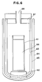
- a block 62 made of foamed styrol was placed in double Dewar vessels 63 and 64 for liquid helium, and a measuring cylinder 61 (300 cc) made of teflon was placed thereon.
- Liquid nitrogen was introduced into a space 65 between the double Dewar vessels 63 and 64.
- the inner Dewar vessel 63 thereafter was sufficiently cooled, and then liquid helium was filled in the inner Dewar vessel 63, thereby cooling the inside of the inner Dewar vessel 63.
- Liquid helium 66 was temporarily, vigorously boiled in the course of the evacuation, but became stable when the temperature of the liquid helium was lowered to 2.17 °K.
- Evacuation to 1 Torr brought its temperature to about 1.3 °K.
- the liquid helium decreased was examined. The result revealed that the helium decreased in the proportion of about 6 cc/hr. Even after 15 hours, the liquid helium at 1.3 °K decreased only by 100 cc or so.
- the liquid helium decreased at a rate of about 100 cc/hr, showing that it decreased far rapidly as compared with the case when the container made of teflon was used.
- Example 1 was repeated to store liquid helium, except that the measuring cylinder made of teflon was not used and instead paraffin was applied to an upper part of the inner wall of the Dewar vessel, and also that the pressure was adjusted to 0.1 Torr.
- the liquid helium decreased in a rate of about 10 cc/hr.
- the liquid helium was stored without coating paraffin, it decreased at a rate of about 150 cc/hr.
- Example 1 a measuring cylinder made of glass was used in place of that made of teflon.
- Streak-like projections were formed by etching at intervals of 5 mm in the peripheral direction of the inner wall surface of the measuring cylinder.
- liquid helium was further poured into the measuring cylinder, followed by cooling under reduced pressure. Cooling to about 1.3 °K brought the pressure to be lowered to 1 Torr or less. When the liquid helium was stored under these conditions it decreased at a rate of 15 cc/hr.
- the liquid helium decreased at a rate of 80 cc/hr or more.
- the space 65 of the double Dewar vessels was filled with liquid nitrogen, and liquid helium was poured into the teflon container receiving the coil, followed by cooling under reduced pressure to lower the temperature of liquid helium to 1.2 °K.
- the saturated vapor pressure at this time was 1 Torr or less.
- the liquid helium in the teflon container decreased at a rate of 20 cc/hr.
- the helium decreased at a rate of 200 cc/hr or more.
- the whole guide was sufficiently cooled to 2.17 °K or less, and thereafter superfluid helium was fed to a liquid helium transporting path 52 formed inside the guide 55. As a result, a surface flow was produced in the direction along the liquid helium transporting path 52 as shown by an arrow 53, whereby the liquid helium could be transported.
- a tube 72 for transporting liquid helium from a liquid helium container 71 in a cryogenic test apparatus 71 to a smaller specimen-cooling system in the apparatus was prepared.
- the container 71 has a volume of 1.5 liter and is made of polytetrafluoroethylene, and the tube 72 is securely fixed to the contained 71.
- This tube 72 is 30 cm long from the container 71 to the specimen cooling system, and the whole apparatus is held in a large Dewar vessel.
- a superfluid helium container having the same purpose as in Example 7 and used in a cryogenic test apparatus as illustrated in Fig. 7B, and also prepared using a pipe of 1/8 inch made of nickel was a pipe 79 for transporting superfluid helium from this container 78 to a specimen-cooling system in the apparatus.
- a number of streak-like grooves 80 were cut on the inner wall of the container 78 in substantially parallel to the liquid surface to prevent the surface flow of helium from rising up and from overflowing outside the container 78.
- a number of streak-like grooves 81 were also cut on the outside of the nickel pipe 79 to prevent helium from being transported along the outside of the pipe 79.
- the superfluid helium was transported along only the inside of the nickel pipe 79 without any particular pump, and reached the specimen 76 with only a minimum vaporization.
- a specimen stand for imparting a temperature difference on specimens under cryogenic temperature prepared was one as illustrated in Fig. 8.
- the specimen stand 90 made of copper was supported by a specimen stand support 86, whose end was immersed in superfluid helium 85.
- Specimens 87 were arranged on the specimen stand 90.
- a heater 88 for controlling temperature was fitted to an end portion of the specimen stand 90 so that the stand may be electrically heated. The whole was held in a thermal insulating container.
- the liquid helium 85 rose up from a helium tank 84 along the specimen stand support 86, reached a polytetrafluoro-ethylene surface layer 82 provided to block the superfluid surface flow, and stopped there.
- the specimen stand support was cooled at the part adjacent to the layer 82.
- heating of the specimen stand support by a heater 88 brought heat to be conducted from the heater area toward the specimen stand support 86 to make temperature gradient on the specimen stand 90, so that the temperature difference could be made among the samples 87 arranged thereon.
- the present invention can block its surface flow, and therefore the helium decreased at a rate lowered to one-several tenth as compared with the conventional methods.
Landscapes
- Engineering & Computer Science (AREA)
- Mechanical Engineering (AREA)
- General Engineering & Computer Science (AREA)
- Physics & Mathematics (AREA)
- Thermal Sciences (AREA)
- Filling Or Discharging Of Gas Storage Vessels (AREA)
Applications Claiming Priority (4)
| Application Number | Priority Date | Filing Date | Title |
|---|---|---|---|
| JP194596/87 | 1987-08-04 | ||
| JP19459687A JPH0686920B2 (ja) | 1987-08-04 | 1987-08-04 | 揮発性物質の保存方法及び保存容器 |
| JP205156/87 | 1987-08-20 | ||
| JP20515687A JPH0629125B2 (ja) | 1987-08-20 | 1987-08-20 | 超流動He表面流の流れ制御方法 |
Publications (3)
| Publication Number | Publication Date |
|---|---|
| EP0308639A2 true EP0308639A2 (de) | 1989-03-29 |
| EP0308639A3 EP0308639A3 (en) | 1989-06-07 |
| EP0308639B1 EP0308639B1 (de) | 1992-12-02 |
Family
ID=26508600
Family Applications (1)
| Application Number | Title | Priority Date | Filing Date |
|---|---|---|---|
| EP88112718A Expired - Lifetime EP0308639B1 (de) | 1987-08-04 | 1988-08-04 | Gefäss zum Aufbewahren von flüssigem Helium |
Country Status (3)
| Country | Link |
|---|---|
| US (2) | US4920753A (de) |
| EP (1) | EP0308639B1 (de) |
| DE (1) | DE3876352T2 (de) |
Cited By (1)
| Publication number | Priority date | Publication date | Assignee | Title |
|---|---|---|---|---|
| EP3287687A1 (de) * | 2016-08-23 | 2018-02-28 | Linde Aktiengesellschaft | Transportbehälter sowie verfahren zum wiegen eines derartigen transportbehälters |
Families Citing this family (4)
| Publication number | Priority date | Publication date | Assignee | Title |
|---|---|---|---|---|
| JPH0825721B2 (ja) * | 1989-08-04 | 1996-03-13 | キヤノン株式会社 | 水素貯蔵体及び該水素貯蔵体への水素貯蔵方法 |
| JP2539121B2 (ja) * | 1991-09-19 | 1996-10-02 | 株式会社日立製作所 | 超伝導磁石 |
| CN110793797A (zh) * | 2019-11-11 | 2020-02-14 | 中国科学院合肥物质科学研究院 | 一种双冷屏负压低温换热器测试装置 |
| CN112146311B (zh) * | 2020-10-23 | 2023-04-21 | 段娜 | 一种反向刀口管式氦-4超流抑制器 |
Family Cites Families (3)
| Publication number | Priority date | Publication date | Assignee | Title |
|---|---|---|---|---|
| CH147556A (fr) * | 1930-09-15 | 1931-06-15 | Hessling Waldemar | Procédé de conservation temporaire de dioxyde de carbone solide et dispositif pour la mise en oeuvre de ce procédé. |
| DE2050171B2 (de) * | 1970-10-13 | 1976-08-26 | Leybold-Heraeus GmbH & Co KG, 5000Köln | Verfahren zum kontinuierlichen erzeugen tiefer temperaturen |
| FR2288956A1 (fr) * | 1973-03-27 | 1976-05-21 | Commissariat Energie Atomique | Procede de reduction de la consommation d'un cryostat et dispositif correspondant |
-
1988
- 1988-07-28 US US07/225,177 patent/US4920753A/en not_active Expired - Lifetime
- 1988-08-04 EP EP88112718A patent/EP0308639B1/de not_active Expired - Lifetime
- 1988-08-04 DE DE8888112718T patent/DE3876352T2/de not_active Expired - Lifetime
-
1990
- 1990-02-16 US US07/480,874 patent/US5065583A/en not_active Expired - Lifetime
Cited By (1)
| Publication number | Priority date | Publication date | Assignee | Title |
|---|---|---|---|---|
| EP3287687A1 (de) * | 2016-08-23 | 2018-02-28 | Linde Aktiengesellschaft | Transportbehälter sowie verfahren zum wiegen eines derartigen transportbehälters |
Also Published As
| Publication number | Publication date |
|---|---|
| DE3876352D1 (de) | 1993-01-14 |
| EP0308639A3 (en) | 1989-06-07 |
| EP0308639B1 (de) | 1992-12-02 |
| DE3876352T2 (de) | 1993-04-01 |
| US5065583A (en) | 1991-11-19 |
| US4920753A (en) | 1990-05-01 |
Similar Documents
| Publication | Publication Date | Title |
|---|---|---|
| US4369636A (en) | Methods and apparatus for reducing heat introduced into superconducting systems by electrical leads | |
| Kell et al. | PVT properties of water-VII. Vapour densities of light and heavy water from 150 to 500° C | |
| Hersee et al. | The operation of metalorganic bubblers at reduced pressure | |
| US20020166326A1 (en) | Vapor plug for cryogenic storage vessels | |
| EP0308639B1 (de) | Gefäss zum Aufbewahren von flüssigem Helium | |
| KR910001925B1 (ko) | 유기금속 화합물의 공급용 용기 및 공급방법 | |
| US4272259A (en) | Gas gettering system | |
| CN1307660C (zh) | 核磁共振成像系统的冷却 | |
| Bogenschütz et al. | Activation Energies in the Chemical Etching of Semiconductors in HNO 3‐HF‐CH 3 COOH | |
| AU627909B2 (en) | Vacuum separator for dewar flask cold exchange systems | |
| Scott | Thermal Design of Large Storage Vessels for Liquid Hydrogen and Helium¹ | |
| US4651117A (en) | Superconducting magnet with shielding apparatus | |
| Nacher et al. | Nuclear polarization enhancement by distillation of liquid− 4 3 He solutions | |
| JPS6428905A (en) | Superconducting magnet | |
| US20090224862A1 (en) | Magnetic apparatus and method | |
| US3041841A (en) | Storage means for a liquefied gas | |
| Glemza et al. | Transient species in oxygen take-up by zinc oxide | |
| JPH0686920B2 (ja) | 揮発性物質の保存方法及び保存容器 | |
| US6367267B1 (en) | Integrated phase separator for ultra high vacuum system | |
| Inai | Experimental investigation of multilayer insulation with room temperature outside and liquid helium temperature inside | |
| Liu et al. | Heat capacity of H2 adsorbed on Ne and on D2 preplated graphite | |
| Lefevre-Seguin et al. | Attempts to increase the nuclear relaxation time of a3He gas at low temperatures | |
| US3036933A (en) | Vacuum evaporation method | |
| Sartain et al. | Cryostat for reactor irradiation | |
| MULTILAYER et al. | N. INAI |
Legal Events
| Date | Code | Title | Description |
|---|---|---|---|
| PUAI | Public reference made under article 153(3) epc to a published international application that has entered the european phase |
Free format text: ORIGINAL CODE: 0009012 |
|
| AK | Designated contracting states |
Kind code of ref document: A2 Designated state(s): CH DE FR GB IT LI NL |
|
| PUAL | Search report despatched |
Free format text: ORIGINAL CODE: 0009013 |
|
| AK | Designated contracting states |
Kind code of ref document: A3 Designated state(s): CH DE FR GB IT LI NL |
|
| 17P | Request for examination filed |
Effective date: 19891207 |
|
| 17Q | First examination report despatched |
Effective date: 19900810 |
|
| RTI1 | Title (correction) | ||
| GRAA | (expected) grant |
Free format text: ORIGINAL CODE: 0009210 |
|
| AK | Designated contracting states |
Kind code of ref document: B1 Designated state(s): CH DE FR GB IT LI NL |
|
| REF | Corresponds to: |
Ref document number: 3876352 Country of ref document: DE Date of ref document: 19930114 |
|
| ET | Fr: translation filed | ||
| ITF | It: translation for a ep patent filed | ||
| PLBE | No opposition filed within time limit |
Free format text: ORIGINAL CODE: 0009261 |
|
| STAA | Information on the status of an ep patent application or granted ep patent |
Free format text: STATUS: NO OPPOSITION FILED WITHIN TIME LIMIT |
|
| 26N | No opposition filed | ||
| REG | Reference to a national code |
Ref country code: GB Ref legal event code: IF02 |
|
| PGFP | Annual fee paid to national office [announced via postgrant information from national office to epo] |
Ref country code: DE Payment date: 20070802 Year of fee payment: 20 |
|
| PGFP | Annual fee paid to national office [announced via postgrant information from national office to epo] |
Ref country code: CH Payment date: 20070727 Year of fee payment: 20 |
|
| PGFP | Annual fee paid to national office [announced via postgrant information from national office to epo] |
Ref country code: GB Payment date: 20070801 Year of fee payment: 20 |
|
| PGFP | Annual fee paid to national office [announced via postgrant information from national office to epo] |
Ref country code: NL Payment date: 20070815 Year of fee payment: 20 Ref country code: IT Payment date: 20070828 Year of fee payment: 20 |
|
| PGFP | Annual fee paid to national office [announced via postgrant information from national office to epo] |
Ref country code: FR Payment date: 20070808 Year of fee payment: 20 |
|
| REG | Reference to a national code |
Ref country code: CH Ref legal event code: PL |
|
| REG | Reference to a national code |
Ref country code: GB Ref legal event code: PE20 Expiry date: 20080803 |
|
| NLV7 | Nl: ceased due to reaching the maximum lifetime of a patent |
Effective date: 20080804 |
|
| PG25 | Lapsed in a contracting state [announced via postgrant information from national office to epo] |
Ref country code: NL Free format text: LAPSE BECAUSE OF EXPIRATION OF PROTECTION Effective date: 20080804 |
|
| PG25 | Lapsed in a contracting state [announced via postgrant information from national office to epo] |
Ref country code: GB Free format text: LAPSE BECAUSE OF EXPIRATION OF PROTECTION Effective date: 20080803 |