EP0308202B1 - Net sheet making apparatus - Google Patents
Net sheet making apparatus Download PDFInfo
- Publication number
- EP0308202B1 EP0308202B1 EP88308504A EP88308504A EP0308202B1 EP 0308202 B1 EP0308202 B1 EP 0308202B1 EP 88308504 A EP88308504 A EP 88308504A EP 88308504 A EP88308504 A EP 88308504A EP 0308202 B1 EP0308202 B1 EP 0308202B1
- Authority
- EP
- European Patent Office
- Prior art keywords
- net sheet
- wind
- warp
- threads
- core member
- Prior art date
- Legal status (The legal status is an assumption and is not a legal conclusion. Google has not performed a legal analysis and makes no representation as to the accuracy of the status listed.)
- Expired - Lifetime
Links
Images

Classifications
-
- D—TEXTILES; PAPER
- D03—WEAVING
- D03J—AUXILIARY WEAVING APPARATUS; WEAVERS' TOOLS; SHUTTLES
- D03J1/00—Auxiliary apparatus combined with or associated with looms
-
- D—TEXTILES; PAPER
- D03—WEAVING
- D03J—AUXILIARY WEAVING APPARATUS; WEAVERS' TOOLS; SHUTTLES
- D03J1/00—Auxiliary apparatus combined with or associated with looms
- D03J1/06—Auxiliary apparatus combined with or associated with looms for treating fabric
-
- B—PERFORMING OPERATIONS; TRANSPORTING
- B29—WORKING OF PLASTICS; WORKING OF SUBSTANCES IN A PLASTIC STATE IN GENERAL
- B29C—SHAPING OR JOINING OF PLASTICS; SHAPING OF MATERIAL IN A PLASTIC STATE, NOT OTHERWISE PROVIDED FOR; AFTER-TREATMENT OF THE SHAPED PRODUCTS, e.g. REPAIRING
- B29C65/00—Joining or sealing of preformed parts, e.g. welding of plastics materials; Apparatus therefor
- B29C65/02—Joining or sealing of preformed parts, e.g. welding of plastics materials; Apparatus therefor by heating, with or without pressure
- B29C65/18—Joining or sealing of preformed parts, e.g. welding of plastics materials; Apparatus therefor by heating, with or without pressure using heated tools
- B29C65/24—Joining or sealing of preformed parts, e.g. welding of plastics materials; Apparatus therefor by heating, with or without pressure using heated tools characterised by the means for heating the tool
- B29C65/30—Electrical means
- B29C65/32—Induction
-
- D—TEXTILES; PAPER
- D04—BRAIDING; LACE-MAKING; KNITTING; TRIMMINGS; NON-WOVEN FABRICS
- D04G—MAKING NETS BY KNOTTING OF FILAMENTARY MATERIAL; MAKING KNOTTED CARPETS OR TAPESTRIES; KNOTTING NOT OTHERWISE PROVIDED FOR
- D04G1/00—Making nets by knotting of filamentary material
- D04G1/02—Making nets by knotting of filamentary material in machines
- D04G1/08—Making nets by knotting of filamentary material in machines using two series of threads
-
- B—PERFORMING OPERATIONS; TRANSPORTING
- B29—WORKING OF PLASTICS; WORKING OF SUBSTANCES IN A PLASTIC STATE IN GENERAL
- B29C—SHAPING OR JOINING OF PLASTICS; SHAPING OF MATERIAL IN A PLASTIC STATE, NOT OTHERWISE PROVIDED FOR; AFTER-TREATMENT OF THE SHAPED PRODUCTS, e.g. REPAIRING
- B29C65/00—Joining or sealing of preformed parts, e.g. welding of plastics materials; Apparatus therefor
- B29C65/02—Joining or sealing of preformed parts, e.g. welding of plastics materials; Apparatus therefor by heating, with or without pressure
- B29C65/18—Joining or sealing of preformed parts, e.g. welding of plastics materials; Apparatus therefor by heating, with or without pressure using heated tools
-
- B—PERFORMING OPERATIONS; TRANSPORTING
- B29—WORKING OF PLASTICS; WORKING OF SUBSTANCES IN A PLASTIC STATE IN GENERAL
- B29C—SHAPING OR JOINING OF PLASTICS; SHAPING OF MATERIAL IN A PLASTIC STATE, NOT OTHERWISE PROVIDED FOR; AFTER-TREATMENT OF THE SHAPED PRODUCTS, e.g. REPAIRING
- B29C66/00—General aspects of processes or apparatus for joining preformed parts
- B29C66/69—General aspects of joining filaments
-
- B—PERFORMING OPERATIONS; TRANSPORTING
- B29—WORKING OF PLASTICS; WORKING OF SUBSTANCES IN A PLASTIC STATE IN GENERAL
- B29C—SHAPING OR JOINING OF PLASTICS; SHAPING OF MATERIAL IN A PLASTIC STATE, NOT OTHERWISE PROVIDED FOR; AFTER-TREATMENT OF THE SHAPED PRODUCTS, e.g. REPAIRING
- B29C66/00—General aspects of processes or apparatus for joining preformed parts
- B29C66/70—General aspects of processes or apparatus for joining preformed parts characterised by the composition, physical properties or the structure of the material of the parts to be joined; Joining with non-plastics material
- B29C66/71—General aspects of processes or apparatus for joining preformed parts characterised by the composition, physical properties or the structure of the material of the parts to be joined; Joining with non-plastics material characterised by the composition of the plastics material of the parts to be joined
-
- B—PERFORMING OPERATIONS; TRANSPORTING
- B29—WORKING OF PLASTICS; WORKING OF SUBSTANCES IN A PLASTIC STATE IN GENERAL
- B29C—SHAPING OR JOINING OF PLASTICS; SHAPING OF MATERIAL IN A PLASTIC STATE, NOT OTHERWISE PROVIDED FOR; AFTER-TREATMENT OF THE SHAPED PRODUCTS, e.g. REPAIRING
- B29C66/00—General aspects of processes or apparatus for joining preformed parts
- B29C66/80—General aspects of machine operations or constructions and parts thereof
- B29C66/83—General aspects of machine operations or constructions and parts thereof characterised by the movement of the joining or pressing tools
- B29C66/834—General aspects of machine operations or constructions and parts thereof characterised by the movement of the joining or pressing tools moving with the parts to be joined
- B29C66/8341—Roller, cylinder or drum types; Band or belt types; Ball types
- B29C66/83411—Roller, cylinder or drum types
-
- B—PERFORMING OPERATIONS; TRANSPORTING
- B29—WORKING OF PLASTICS; WORKING OF SUBSTANCES IN A PLASTIC STATE IN GENERAL
- B29C—SHAPING OR JOINING OF PLASTICS; SHAPING OF MATERIAL IN A PLASTIC STATE, NOT OTHERWISE PROVIDED FOR; AFTER-TREATMENT OF THE SHAPED PRODUCTS, e.g. REPAIRING
- B29C66/00—General aspects of processes or apparatus for joining preformed parts
- B29C66/80—General aspects of machine operations or constructions and parts thereof
- B29C66/83—General aspects of machine operations or constructions and parts thereof characterised by the movement of the joining or pressing tools
- B29C66/834—General aspects of machine operations or constructions and parts thereof characterised by the movement of the joining or pressing tools moving with the parts to be joined
- B29C66/8341—Roller, cylinder or drum types; Band or belt types; Ball types
- B29C66/83411—Roller, cylinder or drum types
- B29C66/83415—Roller, cylinder or drum types the contact angle between said rollers, cylinders or drums and said parts to be joined being a non-zero angle
-
- B—PERFORMING OPERATIONS; TRANSPORTING
- B29—WORKING OF PLASTICS; WORKING OF SUBSTANCES IN A PLASTIC STATE IN GENERAL
- B29C—SHAPING OR JOINING OF PLASTICS; SHAPING OF MATERIAL IN A PLASTIC STATE, NOT OTHERWISE PROVIDED FOR; AFTER-TREATMENT OF THE SHAPED PRODUCTS, e.g. REPAIRING
- B29C66/00—General aspects of processes or apparatus for joining preformed parts
- B29C66/80—General aspects of machine operations or constructions and parts thereof
- B29C66/83—General aspects of machine operations or constructions and parts thereof characterised by the movement of the joining or pressing tools
- B29C66/834—General aspects of machine operations or constructions and parts thereof characterised by the movement of the joining or pressing tools moving with the parts to be joined
- B29C66/8341—Roller, cylinder or drum types; Band or belt types; Ball types
- B29C66/83411—Roller, cylinder or drum types
- B29C66/83417—Roller, cylinder or drum types said rollers, cylinders or drums being hollow
-
- B—PERFORMING OPERATIONS; TRANSPORTING
- B29—WORKING OF PLASTICS; WORKING OF SUBSTANCES IN A PLASTIC STATE IN GENERAL
- B29L—INDEXING SCHEME ASSOCIATED WITH SUBCLASS B29C, RELATING TO PARTICULAR ARTICLES
- B29L2028/00—Nets or the like
Definitions
- the present invention is characterized in that the heating means comprise a roller of the induction heating type with a jacket chamber containing a two-phase heat medium to improve the uniformity of surface temperature by repeating a cycle consisting of evaporation and condensation and forward and rearward tensioning rollers are arranged to wind the woven strip around the heating roller under a predetermined tension.
- a heating roller of the type in question is disclosed in U.K. Patent Specification No. GB-A-1237308.
- the leading end of the net sheet C is first mounted on the wind-up core member 44. Thereafter, the wind-up core member 44 is placed on the wind-up rollers 40 and 42. As the wind-up core member 44 is being rotated by means of the wind-up rollers 40 and 42, the net sheet C is wound around the core member 44 to progressively increase the external diameter of the rolled net sheet. As the external diameter of the rolled net sheet increases, the wind-up core member 44 is lifted while oscillating axially or leftwardly and rightwardly as viewed in Figure 3 by the engagement of the inclined end face 52 of the rotating shaft end 46 with the sloping face 54 of the abutting member 56 and also under the action of the compression spring 62.
- the net sheet will be formed into an unstable roll having a hugely increased diameter from the warp threads thereof being superposed one on another in the rolled structure or that the net sheet will be rolled with skew only in one direction.
- the warp threads on one winding layer in the rolled net sheet can be fallen into between the warp threads on the adjacent winding layer to form a stable net sheet roll.
- the warp covering rate is a percentage of the weaving pitch relative to the warp width and the warp gap rate is a percentage of the weaving rate relative to the warp gap.
Landscapes
- Engineering & Computer Science (AREA)
- Textile Engineering (AREA)
- Physics & Mathematics (AREA)
- Thermal Sciences (AREA)
- Mechanical Engineering (AREA)
- Treatment Of Fiber Materials (AREA)
- Auxiliary Weaving Apparatuses, Weavers' Tools, And Shuttles (AREA)
- Looms (AREA)
Description
- The present invention relates to apparatus for making a net sheet by fusion bonding fusible warp and weft threads together, said apparatus comprising weaving means for weaving the weft threads into the warp threads, a heating device for fusing the threads together, and means for winding up the net sheet.
- An apparatus of this kind is disclosed in U.K. Patent Specification No. GB-A-770678. In that specification loom tension is used to hold the meshes in position while the weft and warp threads are fused together. The heating must be done carefully to avoid causing undesirable flow of the yarns or coalescence of the filaments in the yarns.
- The present invention is characterized in that the heating means comprise a roller of the induction heating type with a jacket chamber containing a two-phase heat medium to improve the uniformity of surface temperature by repeating a cycle consisting of evaporation and condensation and forward and rearward tensioning rollers are arranged to wind the woven strip around the heating roller under a predetermined tension.
- A heating roller of the type in question is disclosed in U.K. Patent Specification No. GB-A-1237308.
- In a net sheet there are gaps at least between the warp threads or weft threads. After the formation of the net the positional relationship between the threads may be disturbed before they are fused so that the desired gaps are not maintained. The invention avoids this difficulty.
- The use as a fusing device of a heating roller of the induction heating type with a two-phase heat medium allows a simplified and small-sized construction which can easily be controlled in temperature to maintain the entire heating part thereof at a uniform temperature, said fusing device being capable of fusion bonding the warp and weft yarns efficiently and positively.
- When the net sheet is rolled, it must not be handled in the same manner as in the conventional woven textiles since when the net sheet is rolled with the warp threads thereof superposed one on another, the roll configuration may collapse from a larger external diameter with the warp threads in a winding layer falling into gaps between the warp threads in the adjacent winding layer. In the latter case, further, the roll configuration may be disturbed to form an undesirable roll shape.
- In one preferred embodiment of the present invention, said winding-up means is axially oscillatable by engagement of the end inclined face of a wind-up core member with the sloping faces of wind-up sidewall portions. The winding-up means is further adapted to axially rock by the wind-up core member upwardly moving between corrugated members which extend vertically between the wind-up sidewall portions.
- In the preferred embodiment, the warp and weft threads can be fused together while maintaining their netted state, so that desirable gaps can easily be formed between the warp threads and between the weft threads. The fusing means is of a simplified and small-sized construction including its heating portion which can be controlled into a uniform temperature to perform the desirable and positive fusion bonding operation. Since the winding-up means is axially oscillatable, there can be provided a net sheet having a stable structure without skew.
- Figure 1 is a schematic layout of one embodiment of a net sheet making apparatus constructed in accordance with the present invention.
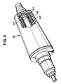
- Figure 2 is a perspective view, partially broken away, of an induction heating roller usable in the present invention.
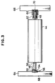
- Figure 3 is a plan view of a wind-up section in the apparatus of the present invention.
- Referring first to Figure 1, there is shown a net sheet making apparatus 1 which comprises a
weaving section 2, a fusing section 4 and a wind-upsection 6, all the sections being substantially integrally installed on abase 8. - The
weaving section 2 rotatably supports awarp yarn roll 12 which includes acylindrical shaft 10 and a plurality of juxtaposed warp threads wound around theshaft 10 without axial gap. Thewarp yarn roll 12 is adapted to receive a given resistance against rotation. -
Guide rollers warp yarn roll 12 to form a path for guiding the warp yarn strip L drawn out of thewarp yarn roll 12. Aheald 18 andreed 19 are disposed in front of the guide roller 16 (leftward as viewed in Figure 1). Theheald 18 is adapted to weave weft threads into between each adjacent warp threads in the warp yarn strip L. Thereed 19 is adapted to arrange the warp threads regularly and to urge the woven weft threads into predetermined position. - In front of the
reed 19 are disposed a woven strip taking-uproller set 26 which comprises aguide roller 22 andpressure rollers heald 18. - The fusing section 4 disposed downstream of the
weaving section 2 comprises aforward tensioning roller 30, aninduction heating roller 32, a rearward tensioning roller 34, aguide roller 36 and aheat cutting device 38, which components are disposed along the direction of movement of the woven strip C in the order as described. The forward andrearward tensioning rollers 30 and 34 are adapted to wind the woven strip C around theinduction heating roller 32 through a range of about 180° under a predetermined tension. - As seen from Figure 2, the
induction heating roller 32 comprises acentral iron core 40, aninduction coil 42 wound around thecore 40 and anoutside jacket chamber 43 located around theinduction coil 42. When theinduction coil 42 is energized a shortcircuiting current is induced circumferentially in the material of the induction roller so that the entireinduction heating roller 32 is self-heated. - The
jacket chamber 43 is an enclosed chamber filled with a mixture consisting of two-phase heat medium, that is, water and steam. Thejacket chamber 43 thus acts to maintain the surface temperature in theroller 32 at a uniform temperature by repeating a cycle consisting of evaporation and condensation. Theinduction heating roller 32 is adapted to urge and fuse the warp and weft threads in the woven strip C against each other while maintaining the surface temperature, for example, at a range of (100°C-160°C) without change beyond 50°C. - Each of the warp and weft threads includes a composite tape material which is composed of an oriented tape core material of thermoplastic resin (high-melting thermoplastic resin) and coating layers of thermoplastic resin having its melting point lower than that of the tape core material (low-melting thermoplastic resin) on the opposite faces of the tape core.
- Such thermoplastic resins include high-density polyethylene, low-density polyethylene, middle-density polyethylene, polypropylene, polyvinyl chloride, polyvinylidene chloride, polystyrene, polyvinyl alcohol, polyacrylonitrile, polyamide, polyester and so on.
- The melting point in the low-melting thermoplastic resin should be at a level such that the orientation of the tape core material will not be influenced by the low-melting temperature. If the tape core material is subjected to a temperature higher than such a low-melting temperature, it would be reduced in strength, leading that the entire net sheet will be reduced in strength. In general, the melting point of the low-melting thermoplastic resin is 15°C-35°C and preferably 20°C-30°C lower than the high-melting point of the high-melting thermoplastic resin. The oriented tape core material is preferably made of high-density polyethylene or polypropylene while the coating layers are preferably formed of low-density polyethylene,. Further, the warp and weft threads may be made of different composite tape materials, respectively.
- Such composite tape materials can be prepared in accordance with any suitable well-known manner. For example, the surface coating layers of low-melting thermoplastic resin may be bonded by fusion or adhesive on the opposite faces of the oriented tape core material. After the thermoplastic coating layer material have been adhered to the opposite faces of the thermoplastic tape core material, the resulting tape core may be slitted into a predetermined width and one-way drawn. Alternatively, the resulting tape core may be one-way drawn and then slitted into a predetermined width. Preferably, a low-melting thermoplastic resin material is fused to the opposite faces of a thermoplastic tape-like material in a composite die machine which utilizes two extruders. The fused materials are then extruded into a laminated film which in turn is drawn.
- The rate of drawing is ranged between 4 and 12 and preferably between 5 and 8.
- The width of the composite tape material is not particularly limited and may be freely designed so that various net patterns can be selected depending on the applications of the net sheet. However, the fineness of the composite tape material is generally ranged between 2.22 x 10⁻⁵ kg/m and 33.33 x 10⁻⁵ kg/m (200 deniers and 3000 deniers).
- The
cutting device 38, which may be heating or blade means, is adapted to trim the opposite side edges of the composite fused strip, that is, the net sheet C. - The wind-up
section 6 comprises a pair of clockwise rotating wind-uprollers core member 44 placed on the wind-up rollers. The wind-upcore member 44 includes a shaft having theopposite ends 46 and 49 which extends axially outwardly beyond the opposite ends of thecore member 44. One of theshaft ends 46 has anend face 52 inclined relative to theaxis 50, that is, positioned relative to the axis with an angle other than 90 degrees. Theinclined end face 52 of theshaft end 46 is engaged by abuttingmember 56 similarly having a slopingface 54 inclined relative to theaxis 50. Theshaft end 48 is received in aspring receiving member 60 through acompression spring 62. The abuttingmember 56 is fixedly mounted on a wind-upsidewall 64 while thespring receiving member 60 is slidably fitted into a vertically extendinggroove 70 which is formed in the other wind-upsidewall 66. - In the winding-up
section 6, the leading end of the net sheet C is first mounted on the wind-upcore member 44. Thereafter, the wind-upcore member 44 is placed on the wind-uprollers up core member 44 is being rotated by means of the wind-uprollers core member 44 to progressively increase the external diameter of the rolled net sheet. As the external diameter of the rolled net sheet increases, the wind-up core member 44 is lifted while oscillating axially or leftwardly and rightwardly as viewed in Figure 3 by the engagement of the inclined end face 52 of therotating shaft end 46 with the slopingface 54 of the abuttingmember 56 and also under the action of thecompression spring 62. Due to such an axial oscillation of thecore member 44, it can be avoided that the net sheet will be formed into an unstable roll having a hugely increased diameter from the warp threads thereof being superposed one on another in the rolled structure or that the net sheet will be rolled with skew only in one direction. In accordance with the present invention, the warp threads on one winding layer in the rolled net sheet can be fallen into between the warp threads on the adjacent winding layer to form a stable net sheet roll. - In another preferred embodiment of the present invention, the wind-
up core member 44 may be arranged with its opposite ends engaged by corrugated faces which are formed on the opposed surfaces of the wind-upsidewalls core member 44 can be axially oscillated between the sidewalls as thecore member 44 moves vertically along the sidewalls. - Although the above embodiments have been described as to the axial oscillation of the wind-
up core member 44, the present invention is not limited to such an arrangement. Namely, the present invention can make various net sheets shown in the following table.
- In the table, the warp covering rate is a percentage of the weaving pitch relative to the warp width and the warp gap rate is a percentage of the weaving rate relative to the warp gap.
- It can be understood from the table that the products C1 through C8 can be rolled very well under the axial oscillation ranged between 4 mm and 8 mm; that the products C7 through C18 can be rolled very well under the axial oscillation ranged between 2 mm and 4 mm; and that the products C14 through C19 can be rolled, without any axial oscillation, into a stable net sheet roll having no skew in one direction.
- When each of the products C1 through C13 was to be rolled with an axial oscillation less than said values or without any axial oscillation, the net sheet was rolled with its corrugated intermediate region wit the opposite end faces thereof being recessed. When such a rolled net sheet was unwound, the corrugated intermediate region of the net sheet did not disappear. As a result, the width of the net sheet was decreased from the desired width. If such a net sheet is subjected to laminating, sewing and other workings, a net product lacking in width would be produced. It is of course that when the net sheet roll itself is to be sold as a final product, the recessed end faces of the net sheet roll will degrade its commercial quality. If the corrugated intermediate region of the rolled net sheet is increased in degree, the reduction of width and the degradation of commercial quality will further be emphasized.
- Moreover, the net sheet roll produced without any axial oscillation tends to be reduced in strength. If such net sheet rolls are stored under the side-by-side superposed condition, the circular cross-section of each of the rolls will be damaged into any undesirable deformed cross-section other than circle. As a result, when the deformed net sheet roll is to be unwound while braking the rotating net sheet roll, the braking is not efficiently performed. This means that a high-quality net sheet product cannot be provided.
- The invention has thus been shown and described with reference to specific embodiments, however, it should be noted that the invention is in no way limited to the details of the illustrated structures but changes and modifications may be made without departing from the scope of the appended claims.
Claims (4)
- An apparatus for making a net sheet by fusion bonding fusible warp and weft threads together, said apparatus comprising weaving means (2) for weaving the weft threads into the warp threads, a heating device (32) for fusing the threads together, and means (6) for winding up the net sheet (C) characterized in that the heating means comprise a roller (32) of the induction heating type with a jacket chamber (43) containing a two-phase heat medium to improve the uniformity of surface temperature by repeating a cycle consisting of evaporation and condensation and forward and rearward tensioning rollers (30, 34) are arranged to wind the woven strip around the heating roller (32) under a predetermined tension.
- An apparatus as claimed in claim 1 characterized in that the winding means is so constructed that the roll of net sheet is oscillated axially as the net sheet is wound up.
- An apparatus as defined in claim 1, wherein said winding means is axially oscillated by engagement of the inclined end face (52) of a wind-up core member (44) with the sloping face (54) of a wind-up sidewall (64).
- An apparatus as defined in claim 1, wherein said winding means includes a wind-up core member (44) adapted to axially oscillate while upwardly moving between vertically extending and corrugated members on the opposed wind-up sidewalls (64, 66).
Applications Claiming Priority (4)
| Application Number | Priority Date | Filing Date | Title |
|---|---|---|---|
| JP230759/87 | 1987-09-14 | ||
| JP23075987 | 1987-09-14 | ||
| JP63133816A JPH01162848A (en) | 1987-09-14 | 1988-05-31 | Reticulated sheet manufacturing equipment |
| JP133816/88 | 1988-05-31 |
Publications (3)
| Publication Number | Publication Date |
|---|---|
| EP0308202A2 EP0308202A2 (en) | 1989-03-22 |
| EP0308202A3 EP0308202A3 (en) | 1990-06-13 |
| EP0308202B1 true EP0308202B1 (en) | 1994-07-27 |
Family
ID=26468064
Family Applications (1)
| Application Number | Title | Priority Date | Filing Date |
|---|---|---|---|
| EP88308504A Expired - Lifetime EP0308202B1 (en) | 1987-09-14 | 1988-09-14 | Net sheet making apparatus |
Country Status (5)
| Country | Link |
|---|---|
| EP (1) | EP0308202B1 (en) |
| JP (1) | JPH01162848A (en) |
| KR (1) | KR890005320A (en) |
| AU (1) | AU614538B2 (en) |
| DE (1) | DE3850830T2 (en) |
Families Citing this family (5)
| Publication number | Priority date | Publication date | Assignee | Title |
|---|---|---|---|---|
| JP2911648B2 (en) * | 1991-07-09 | 1999-06-23 | ダイヤテックス株式会社 | Reticulated sheet manufacturing equipment |
| RU2127782C1 (en) * | 1998-05-21 | 1999-03-20 | Иванов Вадим Петрович | Method of manufacturing guard device net |
| FR2799213B1 (en) * | 1999-10-05 | 2001-11-30 | Ncv Ind | DEVICE AND METHOD FOR MANUFACTURING FABRIC, FABRIC OBTAINED BY SUCH PROCESS, AND USE OF SUCH FABRIC FOR MANUFACTURING INFLATABLE SAFETY CUSHIONS |
| GR1006889B (en) * | 2005-04-11 | 2010-07-19 | Καρατζη Βιομηχανικες Ξενοδοχειακες Επιχειρησεις Α.Ε., | Manufacture of webs with controlled properties formed of multilayer synthetic yarns |
| KR100935791B1 (en) * | 2009-07-27 | 2010-01-06 | 송금순 | Method of manufacturing fabric treated with heat and apparatus thereof |
Family Cites Families (7)
| Publication number | Priority date | Publication date | Assignee | Title |
|---|---|---|---|---|
| GB770678A (en) * | 1953-07-02 | 1957-03-20 | Bay Statf Abrasive Products Co | Durable open mesh fabric and process of making same |
| GB1237308A (en) * | 1969-10-02 | 1971-06-30 | Mitsubishi Heavy Ind Ltd | A temperature control device for a rotary heating roll |
| BE756850A (en) * | 1969-10-03 | 1971-03-30 | Sulzer Ag | DEVICE FOR WINDING UP THE FABRIC COMING OUT OF A TRADE OR A TREATMENT MACHINE |
| GB1352845A (en) * | 1970-04-08 | 1974-05-15 | Ashworth & Co Ltd T | Weaving and apparatus therefor |
| JPS52118097A (en) * | 1976-03-25 | 1977-10-04 | Kousui Kinefuchi | Preventing method of stitch lag of rough fabric |
| FR2439253A1 (en) * | 1978-10-19 | 1980-05-16 | Amengual Rotger | plasticised woven fabric - made by heating fabric to melt and swell synthetic fibres directly after weaving (PT 17.7.79) |
| AT365673B (en) * | 1979-04-19 | 1982-02-10 | Vogel Werner Ing | DEVICE FOR PRODUCING A GRID-SHAPED FABRIC |
-
1988
- 1988-05-31 JP JP63133816A patent/JPH01162848A/en active Pending
- 1988-09-13 KR KR1019880011807A patent/KR890005320A/en not_active Withdrawn
- 1988-09-14 AU AU22206/88A patent/AU614538B2/en not_active Expired
- 1988-09-14 EP EP88308504A patent/EP0308202B1/en not_active Expired - Lifetime
- 1988-09-14 DE DE3850830T patent/DE3850830T2/en not_active Expired - Lifetime
Also Published As
| Publication number | Publication date |
|---|---|
| AU2220688A (en) | 1989-03-16 |
| EP0308202A3 (en) | 1990-06-13 |
| AU614538B2 (en) | 1991-09-05 |
| DE3850830D1 (en) | 1994-09-01 |
| JPH01162848A (en) | 1989-06-27 |
| DE3850830T2 (en) | 1995-01-12 |
| KR890005320A (en) | 1989-05-13 |
| EP0308202A2 (en) | 1989-03-22 |
Similar Documents
| Publication | Publication Date | Title |
|---|---|---|
| US5394906A (en) | Method and apparatus for weaving curved material preforms | |
| EP0138294A2 (en) | method and apparatus for producing blends of resinuous thermoplastic fiber and laminated structures produced therefrom | |
| US4351889A (en) | Tubular bodies for use in a positive plate of a lead-acid storage battery | |
| JP2001520709A (en) | Fabric containing tape-like warp and weft and device for producing this fabric | |
| JPH03504401A (en) | Spiral-shaped textile structures, methods for obtaining such structures and corresponding looms | |
| AU614538B2 (en) | Net sheet making apparatus | |
| US6450211B1 (en) | Weaving process for a high-density fabric on a water-jet loom | |
| JP3397480B2 (en) | Endless multilayer fabric for concentrating paper material and method for producing the same | |
| CN110461746A (en) | Yarn package and manufacturing method thereof | |
| CA1067280A (en) | Fabrics and methods of making fabrics from synthetic tapes | |
| EP3235949B1 (en) | Papermaking felt | |
| US3562770A (en) | Separable fastener of the flexible hooking type | |
| KR101845689B1 (en) | 0°uni-directional filament prepreg, method of manufacturing the same and method of multi-axis prepreg composite thereby | |
| JP2911648B2 (en) | Reticulated sheet manufacturing equipment | |
| US5806775A (en) | Self-supporting yarn package | |
| EP0021793A1 (en) | A textured tubular body for use in a tubular storage battery plate and a method of making that body | |
| US3123968A (en) | flanigan | |
| US5839678A (en) | Method of controlling flat spots in a zero twist yarn | |
| US5690150A (en) | Woven fabric made with a yarn having periodic flat spots | |
| AU715539B2 (en) | A strand | |
| JP3719922B2 (en) | Method for producing fiber woven fabric for FRP and method for producing prepreg for FRP | |
| US3875975A (en) | Textile fabric roll and method | |
| US3608025A (en) | Slitting to form filaments | |
| JP3169420B2 (en) | Nonwoven fabric for reinforcement and method for producing the same | |
| JP2021055195A (en) | Felt for use in paper making, and method of producing the same |
Legal Events
| Date | Code | Title | Description |
|---|---|---|---|
| PUAI | Public reference made under article 153(3) epc to a published international application that has entered the european phase |
Free format text: ORIGINAL CODE: 0009012 |
|
| AK | Designated contracting states |
Kind code of ref document: A2 Designated state(s): DE FR GB IT |
|
| PUAL | Search report despatched |
Free format text: ORIGINAL CODE: 0009013 |
|
| AK | Designated contracting states |
Kind code of ref document: A3 Designated state(s): DE FR GB IT |
|
| 17P | Request for examination filed |
Effective date: 19901211 |
|
| 17Q | First examination report despatched |
Effective date: 19920515 |
|
| GRAA | (expected) grant |
Free format text: ORIGINAL CODE: 0009210 |
|
| ITF | It: translation for a ep patent filed | ||
| AK | Designated contracting states |
Kind code of ref document: B1 Designated state(s): DE FR GB IT |
|
| REF | Corresponds to: |
Ref document number: 3850830 Country of ref document: DE Date of ref document: 19940901 |
|
| ET | Fr: translation filed | ||
| PLBE | No opposition filed within time limit |
Free format text: ORIGINAL CODE: 0009261 |
|
| STAA | Information on the status of an ep patent application or granted ep patent |
Free format text: STATUS: NO OPPOSITION FILED WITHIN TIME LIMIT |
|
| 26N | No opposition filed | ||
| REG | Reference to a national code |
Ref country code: GB Ref legal event code: IF02 |
|
| PGFP | Annual fee paid to national office [announced via postgrant information from national office to epo] |
Ref country code: DE Payment date: 20070829 Year of fee payment: 20 |
|
| PGFP | Annual fee paid to national office [announced via postgrant information from national office to epo] |
Ref country code: GB Payment date: 20070912 Year of fee payment: 20 |
|
| PGFP | Annual fee paid to national office [announced via postgrant information from national office to epo] |
Ref country code: IT Payment date: 20070911 Year of fee payment: 20 |
|
| PGFP | Annual fee paid to national office [announced via postgrant information from national office to epo] |
Ref country code: FR Payment date: 20070730 Year of fee payment: 20 |
|
| REG | Reference to a national code |
Ref country code: GB Ref legal event code: PE20 Expiry date: 20080913 |
|
| PG25 | Lapsed in a contracting state [announced via postgrant information from national office to epo] |
Ref country code: GB Free format text: LAPSE BECAUSE OF EXPIRATION OF PROTECTION Effective date: 20080913 |