EP0307601B1 - Apparatus switch with switch-on protection - Google Patents
Apparatus switch with switch-on protection Download PDFInfo
- Publication number
- EP0307601B1 EP0307601B1 EP88112523A EP88112523A EP0307601B1 EP 0307601 B1 EP0307601 B1 EP 0307601B1 EP 88112523 A EP88112523 A EP 88112523A EP 88112523 A EP88112523 A EP 88112523A EP 0307601 B1 EP0307601 B1 EP 0307601B1
- Authority
- EP
- European Patent Office
- Prior art keywords
- switch
- locking
- appliance
- engagement means
- legs
- Prior art date
- Legal status (The legal status is an assumption and is not a legal conclusion. Google has not performed a legal analysis and makes no representation as to the accuracy of the status listed.)
- Expired - Lifetime
Links
Images


Classifications
-
- H—ELECTRICITY
- H01—ELECTRIC ELEMENTS
- H01H—ELECTRIC SWITCHES; RELAYS; SELECTORS; EMERGENCY PROTECTIVE DEVICES
- H01H3/00—Mechanisms for operating contacts
- H01H3/02—Operating parts, i.e. for operating driving mechanism by a mechanical force external to the switch
- H01H3/20—Operating parts, i.e. for operating driving mechanism by a mechanical force external to the switch wherein an auxiliary movement thereof, or of an attachment thereto, is necessary before the main movement is possible or effective, e.g. for unlatching, for coupling
Landscapes
- Switch Cases, Indication, And Locking (AREA)
- Emergency Protection Circuit Devices (AREA)
- Push-Button Switches (AREA)
- Dry Shavers And Clippers (AREA)
- Slide Switches (AREA)
- Keying Circuit Devices (AREA)
- Electrophonic Musical Instruments (AREA)
Abstract
Description
Die Erfindung bezieht sich auf einen Schalter für ein Gerät des persönlichen Bedarfs, bestehend aus einem Geräteschalter zur Ein- und Ausschaltung eines in einem Gerätegehäuse vorgesehenen, elektrisch betreibbaren Antriebsteiles sowie einem Arretierungsschalter, der in den Schaltweg des Geräteschalters bewegbar ist.The invention relates to a switch for a device for personal use, consisting of a device switch for switching on and off an electrically operated drive part provided in a device housing and a locking switch which can be moved in the switching path of the device switch.
Es ist bereits ein automatischer Einschaltschutz für aufladbare elektrische Rasierapparate und Zahnbürsten bekannt, der aus einem im Gehäuse gelagerten, gegen die Wirkung einer Feder bewegbaren Stößel besteht, dessen inneres Ende in den Einschaltweg eines in Ausschaltstellung befindlichen Ein- und Ausschaltteils verschiebbar ist. Der Stellweg des Stößels verläuft dabei quer zum Stellweg des Ein- und Ausschalters, so daß relativ viel Platz für den Einschaltschutz zur Verfügung gestellt werden muß (DE-A-33 15 643).There is already known an automatic switch-on protection for rechargeable electric shavers and toothbrushes, which consists of a plunger mounted in the housing and movable against the action of a spring, the inner end of which can be displaced into the switch-on path of a switch-on and switch-off part which is in the switch-off position. The stroke of the plunger is transverse to the stroke of the on and off switch, so that a relatively large amount of space for the switch-on protection must be made available (DE-A-33 15 643).
Aus der DE-A-33 09 221 ist ein Trockenrasierapparat bekannt mit einem auf einer Leiterplatte angeordneten als Druckschalter ausgebildeten Ein- und Ausschalter und einem quer zur Betätigungsrichtung des Ein- und Ausschalters verschiebbar angeordneten Arretierungsschalter zur Verriegelung bzw. Entriegelung des Ein- und Ausschalters.From DE-A-33 09 221 a dry shaving apparatus is known with an on and off switch arranged on a printed circuit board as a pressure switch and a locking switch arranged transversely to the actuation direction of the on and off switch for locking or unlocking the on and off switch.
Aus der US-A-45 63 553 ist bekannt, einem in zwei Schaltstellungen bewegbaren Stufenschalter eines elektronischen Gerätes einen quer zur Bewegungsrichtung des Stufenschalters bewegbaren Stoppschalter zuzuordnen, um ein Durchschalten des Stufenschalters in eine zweite Schaltstellung zu verhindern.From US-A-45 63 553 it is known to assign a step switch which is movable in two switch positions of an electronic device to a stop switch which is movable transversely to the direction of movement of the step switch in order to prevent the step switch from being switched through to a second switch position.
Demgegenüber liegt der Erfindung die Aufgabe zugrunde, einen Schalter der eingangs genannten Gattung zu schaffen, bei dem ein in Ausschaltstellung befindlicher Geräteschalter gegen jegliche Betätigung in die Einschaltstellung zuverlässig gesichert ist. Der Schalter soll darüber hinaus einfach zu handhaben, auf kleinstmöglichem Raum unterzubringen sowie mit einer geringstmöglichen Anzahl von Bauteilen ausgestattet sein.In contrast, the invention has for its object to provide a switch of the type mentioned, in which a device switch in the off position is reliably secured against any actuation in the on position. The switch should also be easy to use, accommodate in the smallest possible space and be equipped with the smallest possible number of components.
Diese Aufgabe wird bei einem Schalter der eingangs genannten Art dadurch gelöst, daß der Arretierungsschalter und der Geräteschalter beim Aus- bzw. Einschalten jeweils in der gleichen Richtung geradlinig bewegbar sind, daß der Geräteschalter und/oder der Arretierungsschalter Form- und/oder Kraftschlußelemente aufweisen, die ineinander verschiebbar bzw. in Eingriff bringbar sind, um den Geräteschalter mittels des Arretierungsschalters in Ausschaltstellung zu sichern, und daß der Geräteschalter sowie der Arretierungsschalter auf einem Tragteil des Gerätegehäuses aufgenommen sind.This object is achieved in the case of a switch of the type mentioned at the outset in that the locking switch and the device switch can each be moved in a straight line in the same direction when the device is switched on and off, and that the device switch and / or the locking switch have positive and / or non-positive locking elements, which can be moved into one another or brought into engagement in order to secure the device switch in the off position by means of the locking switch, and that the device switch and the locking switch are accommodated on a supporting part of the device housing.
Dies ergibt eine sehr platzsparende Ausbildung des Schalters und eine minimale Bauhöhe.This results in a very space-saving design of the switch and a minimal overall height.
Mittels Verwendung von ineinander in Eingriff bringbaren Formschluß- und Kraftschlußelementen, die an dem Geräteschalter und an dem Arretierungsschalter vorgesehen sind, lassen sich Geräteschalter sowie auch der Arretierungsschalter in der Ausschaltstellung des Geräteschalters auf einfache Weise miteinander verkeilen, so daß eine sichere Arretierung eines in Ausschaltstellung befindlichen Geräteschalters gegen Betätigungen jeglicher Art, insbesondere unbeabsichtigte Betätigungen gegeben ist.By using interlocking interlocking and force-locking elements which are provided on the device switch and on the locking switch, the device switch and also the locking switch can be wedged together in a simple manner in the off position of the device switch, so that a secure locking of one in the off position Device switch against operations of any kind, in particular unintentional operations.
Die vorliegende Erfindung läßt verschiedene Ausführungsformen zu, deren gemeinsamer Vorteil darin besteht, daß sämtliche Form- und/oder Kraftschlußelemente in entsprechender Abstimmung zueinander an drei einander zugeordneten Bauteilen des Gerätes, und zwar der feststehenden Trennwand des Gehäuses bzw. der Gehäusewand, dem Geräteschalter und dem Arretierungsschalter angeformt bzw. eingeformt sind.The present invention allows various embodiments, the common advantage of which is that all form-locking and / or force-locking elements in corresponding coordination with one another on three mutually associated components of the device, namely the fixed partition of the housing or the housing wall, the device switch and the Locking switches are molded or molded.
Vorzugsweise weist der Geräteschalter wenigstens ein Formschlußelement auf, das mittels wenigstens einem am Tragteil vorgesehenen Rastelement in vorgegebenen Schaltpositionen gehalten ist. Zum Zwecke der Arretierung weist der Arretierungsschalter Arretierungsteile auf, die in am Tragteil vorgesehenen Rastpositionen verschiebbar sind. Nach einer Ausführungsform der Erfindung besteht das Formschlußelement des Geräteschalters aus einem federelastischen, L-förmigen Arretierungsteil mit einem am Schenkel angeformten Noppen. Nach einer weiteren Ausführungsform der Erfindung ist das Formschlußelement des Geräteschalters als U-förmiger Arretierungsbügel ausgebildet, wobei an dessen elastisch ausgebildeten Schenkeln jeweils ein Noppen angeformt ist. Nach einer Ausführungsform der Erfindung ist das Formschlußelement des Geräteschalters als Bolzen am Geräteschalter angeformt. Nach einer Ausführungsform der Erfindung ist das Rastelement aus einem zwischen zwei im Tragteil vorgesehenen Langlochöffnungen befindlichen Steg gebildet. Nach einer Ausführungsform der Erfindung ist das Rastelement als Bolzen am Tragteil angeformt. Nach einer Ausführungsform der Erfindung besteht das Rastelement aus einem an der Trennwand angeformten, U-förmigen Artetierungsbügel, an dessen federelastischen Schenkeln jeweils ein Noppen angeformt ist. Um ein Herausgleiten der Formschlußelemente des Geräteschalters aus bestimmten vorgegebenen Rastpositionen zu verhindern, weist der Arretierungsschalter wenigstens ein Kraftschlußelement auf, das in den Federweg der Formschlußelemente des Geräteschalters verschiebbar ist.The device switch preferably has at least one form-locking element which is held in predetermined switching positions by means of at least one latching element provided on the support part. For the purpose of locking, the locking switch has locking parts which are displaceable in the locking positions provided on the support part. According to one embodiment of the invention, the form-locking element of the device switch consists of a spring-elastic, L-shaped locking part with a knob formed on the leg. According to a further embodiment of the invention, the form-locking element of the device switch is designed as a U-shaped locking bracket, with a knob being formed on each of its elastic legs. According to one embodiment of the invention, the positive locking element of the device switch is molded onto the device switch as a bolt. According to one embodiment of the invention, the locking element is formed from a web located between two slot openings provided in the support part. According to one embodiment of the invention, the locking element is formed as a bolt on the support part. According to one embodiment of the invention, the latching element consists of a U-shaped articulation bracket formed on the partition, on the resilient legs of which a knob is molded. In order to prevent the form-locking elements of the device switch from sliding out of certain predetermined latching positions, the locking switch has at least one force-locking element which is displaceable in the spring travel of the form-locking elements of the device switch.
Nach einer weiteren Ausführungsform wird zuvor genannte Wirkung dadurch erzielt, daß der Arretierungsschalter wenigstens ein Kraftschlußelement aufweist, das in den Federweg der federelastischen Schenkel des Rastelementes der Trennwand verschiebbar ist. Vorzugsweise ist das Kraftschlußelement als L-förmiges Arretierungsteil ausgebildet, das in Ausschaltstellung des Geräteschalters auf dessen Formschlußelement aufschiebbar ist. Nach einer weiteren Ausführungsform ist das Kraftschlußelement als U -förmiger Arretierungsbügel ausgebildet, dessen Schenkel in Ausschaltstellung des Geräteschalters auf die Schenkel des Formschlußelementes des Geräteschalters aufschiebbar sind. Nach einer anderen Ausführungsform ist das Kraftschlußelement als U-förmiger Arretierungsbügel ausgebildet, dessen die Schenkel verbindender Bügelsteg zwischen die Schenkel des Formschlußelementes schiebbar ist. Durch die an den Arretierungsteilen des Geräteschalters sowie des Arretierungsschalters vorgesehenen Noppen wird mit einfachen baulichen Mitteln eine Schaltfolge beider Schalter, einschließlich einer Arretierung, dadurch bewerkstelligt, daß für die Noppen beider Schalter in wenigstens einer der Längsseitenwände des Tragteiles die Rastpositionen mittels angeformter Vorsprünge gebildet sind.According to a further embodiment, the above-mentioned effect is achieved in that the locking switch has at least one force-locking element which is displaceable in the spring travel of the resilient legs of the locking element of the partition. The force-locking element is preferably designed as an L-shaped locking part which can be pushed onto the form-locking element in the switched-off position of the device switch. According to a further embodiment, the force-locking element is designed as a U-shaped locking bracket, the legs of which can be pushed onto the legs of the form-locking element of the device switch in the switched-off position of the device switch. According to another embodiment, the force-locking element is designed as a U-shaped locking bracket, the arm web connecting the legs of which can be pushed between the legs of the form-locking element. Through the knobs provided on the locking parts of the device switch and the locking switch, a switching sequence of both switches, including a locking, is accomplished with simple structural means in that the locking positions for the knobs of both switches are formed in at least one of the longitudinal side walls of the supporting part by means of molded projections.
Weitere Vorteile und Einzelheiten der Erfindung ergeben sich aus der nachfolgenden Beschreibung und den Zeichnungen, in denen einige bevorzugte Ausführungsbeispiele dargestellt sind, und zwar zeigen:
- Fig. 1
- eine Explosionsdarstellung der Bauteile eines Schalters in Perspektive von oben,
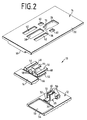
- Fig. 2
- eine Explosionsdarstellung des Schalters nach Fig. 1 in Perspektive von unten,
- Fig. 3a
- eine Schnittdarstellung durch den Schalter nach Fig. 1 und 2,
- Fig. 3b
- eine Schnittdarstellung des Schalters nach Fig. 1 und 2, mit einem in Ausschaltstellung befindlichen Geräteschalter und einem diesen sperrenden Arretierungsschalter,
- Fig. 3c
- eine Schnittdarstellung des Schalters nach Fig. 1 und 2, mit einem vom Arretierungsschalter freigegebenen, in Einschaltstellung befindlichen Geräteschalter,
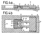
- Fig. 4a
- eine Schnittdarstellung eines Schalters mit am Geräteschalter sowie am Arretierungsschalter angeformten U-förmigen Arretierungsbügeln,
- Fig. 4b
- eine weitere Schnittdarstellung des Schalters nach Fig. 4a,
- Fig. 5a
- ein weiteres Ausführungsbeispiel eines Geräteschalters im Schnitt,
- Fig. 5b
- eine Draufsicht des Schalters nach Fig. 5a in Schnittdarstellung, wobei der Arretierungsschalter mit parallel zueinander verlaufenden, Noppen aufweisenden, Schenkeln ausgerüstet ist, die in der Ausstellung des Geräteschalters einen Bolzen umklammern,
- Fig. 5c
- eine Schnittdarstellung des Schalters nach Fig. 5a und Fig. 5b in Betriebsstellung,
- Fig. 5d
- Einzelheiten der Rasteinrichtung des Arretierungsschalters im Schnitt,
- Fig. 6a
- ein weiteres Ausführungsbeispiel eines Schalters mit U-förmigen Arretierungsteilen im Schnitt,
- Fig. 6b
- eine Draufsicht des Geräteschalters nach Fig. 6a in Schnittdarstellung.
- Fig. 1
- an exploded view of the components of a switch in perspective from above,
- Fig. 2
- 2 shows an exploded view of the switch according to FIG. 1 in perspective from below,
- Fig. 3a
- 2 shows a sectional view through the switch according to FIGS. 1 and 2,
- Fig. 3b
- 2 shows a sectional view of the switch according to FIGS. 1 and 2, with a device switch in the off position and a locking switch blocking it,
- Fig. 3c
- 1 and 2, with a device switch released by the locking switch and in the switched-on position,
- Fig. 4a
- 2 shows a sectional illustration of a switch with U-shaped locking brackets molded onto the device switch and onto the locking switch,
- Fig. 4b
- 4a shows a further sectional illustration of the switch according to FIG.
- Fig. 5a
- another embodiment of a device switch in section,
- Fig. 5b
- 5a shows a sectional view of the switch according to FIG. 5a, the locking switch being equipped with legs which run parallel to one another and have knobs which clasp a bolt in the display of the device switch,
- Fig. 5c
- 5a and 5b in the operating position,
- Fig. 5d
- Details of the locking device of the locking switch in section,
- Fig. 6a
- another embodiment of a switch with U-shaped locking parts in section,
- Fig. 6b
- a plan view of the device switch of FIG. 6a in a sectional view.
In den Figuren 1 und 2 sind die einzelnen Teile einer Ausführungsform eines Schalters 10 für ein Gerät des persönlichen Bedarfs, beispielsweise für einen Elektrorasierer oder eine Zahnbürste perspektivisch dargestellt. Diese Ausführungsform ist in den nachfolgenden Figuren 3a bis 3c im zusammengebauten Zustand im Schnitt dargestellt und wird nachfolgend anhand dieser Figuren näher erläutert.FIGS. 1 and 2 show the individual parts of an embodiment of a
Der Schalter 10 besteht aus einem Geräteschalter 12 und einem Arretierungsschalter 14, die in einem Tragteil 16 verschiebbar aufgenommen sind. Das Tragteil 16 ist Bestandteil eines in der Zeichnung nicht dargestellten Gehäuses, in dem ein elektrisch betriebbares Antriebsteil zum Betrieben des Gerätes vorgesehen ist. Das Tragteil 16 besteht aus einer in der Gehäusewandung des Gerätes vorgesehenen, der Aufnahme des Geräteschalters 12 und des Arretierungsschalters 14 dienenden, rechteckigen Vertiefung bzw. Aussparung 24, mit einem vorderen Begrenzungsteil 18 und einem hinteren Begrenzungsteil 20.The
Auf der Symmetrieachse des Tragteiles 16 ist eine rechteckförmige Offnung 26 vorgesehen, die zur Aufnahme eines L-förmig ausgebildeten Arretierungsteiles 28 dient, dessen zur Unterseite 30 des Tragteiles 16 parallel verlaufender Schenkel 32 endseitig eine Noppe 34 aufweist, die in der Betriebsstellung des Geräteschalters 12 gegen einen Steg 36 des Tragteiles 16 anliegt. Der Steg 36 begrenzt das linke Ende der Offnung 26 und das rechte Ende einer Langlochöffnung 38, die zur Aufnahme des Noppens 34 dient, wenn der Geräteschalter 12 gemäß Fig. 3c nach links verstellt worden ist. In dieser Stellung befindet sich der am Schenkel 32 des Arretierungsteiles 28 vorgesehene Noppen 34 in der Langlochöffnung 38. Das L-förmige Arretierungsteil 44 ist an dem Arretierungsschalter 14 angeformt und erstreckt sich durch die sich an den Steg 36 anschließende Langlochöffnung 38. Parallel zu der Langlochöffnung 38 verlaufen zwei weitere Langlochöffnungen 40, die etwas kürzer ausgebildet sind als die Langlochöffnung 38. Die Langlochöffnungen 40 dienen zur Aufnahme von zwei ebenfalls L-förmigen Arretierungsteilen 46, die endseitig jeweils mit Noppen 48 ausgestattet sind. Die Arretierungsteile 28 und 46 sind in vorteilhafter Weise federelastisch ausgebildet, so daß diese beim Entlanggleiten auf der Unterseite 30 des Tragteiles 16 etwas nach oben gebogen werden, bis die Noppen 34 und 48 in entsprechende Aussparungen einrasten.A
Damit das Arretierungsteil 44 des Arretierungsschalters 14 auf das Arretierungsteil 28 des Geräteschalters 12 aufgeschoben werden kann, wenn sich der Geräteschalter 12 in seiner Ausstellung gemäß Fig. 3b befindet, ist der Geräteschalter 12 mit einer Aussparung 50 versehen, in die das vordere Endteil 52 des Arretierungsschalters 14 geschoben werden kann, bis die Stirnseite 66 des Arretierungsschalters 14 zur Anlage an die Stirnseite 54 des Geräteschalters 12 gelangt.So that the locking
Der Arretierungsteil 28 des Geräteschalters 12 weist beiderseits des Arretierungsteiles 28 kleine Haken 56 auf, die an der Unterseite 30 des Tragteiles 16 anliegen und die mit dem Geräteschalter 12 fest verbunden sind. Die Haken 56 erstrecken sich ebenfalls durch die Offnung 26 und sichern das Arretierungsteil 28 gegen Herausrutschen aus der Offnung 26. Soll der Geräteschalter 12 mit dem Arretierungsteil 28 aus der Offnung 26 herausgenommen werden, so brauchen lediglich die beiden gegenüberliegenden Hakenteile 56 ein wenig zusammengedrückt werden, so daß der obere Teil des Hakenteiles nicht mehr gegen die Unterseite 30 des Tragteiles 16 anliegt. Der Geräteschalter 12 läßt sich dann ohne weiteres aus der Offnung 26 herausziehen. Zur Sicherung des Arretierungsschalters 14 sind ebenfalls zwei Haken 58 an dem Arretierungsschalter 14 angeordnet, die gem. Fig. 3a bis 3c dem Arretierungsschalter 14 am Tragteil 16 sichern und eine Verstellung des Arretierungsschalters 14 zulassen. Die beiden parallel zueinander verlaufenden Arretierungsteile 46 des Arretierungschalters 14 rasten mit ihren Noppen 48 in Vertiefungen bzw. Aussparungen 60 ein, wenn der Arretierungsschalter gemäß Fig. 3b ganz nach rechts verschoben worden ist.The locking
In Fig. 3b befindet sich der Geräteschalter 12 in seiner Ausstellung und ist durch den Arretierungsschalter 14 gegen unbeabsichtigtes Verstellen gesichert. In Fig. 3a nehmen der Arretierungschalter 14 und der Geräteschalter 12 eine Mittelstellung ein, in der die Noppen 48 der Schenkel 46 des Arretierungsschalters 14 sowie die Rippe 34 des Schenkels 32 des Geräteschalters an dem Steg 36 federelastisch anliegen. Wird beispielsweise der Geräteschalter 12 gem. Fig. 3b ganz nach rechts in eine Ausschaltstellung verstellt, so liegt der Geräteschalter 12 mit seinem Griffteil gegen eine Kante 62 des Begrenzungsteils 20 des Tragteiles 16 an, so daß eine weitere Verstellung des Geräteschalters 12 nach rechts verhindert wird. Gleichzeitig wird der Noppen 34 hinter den Steg 36 bewegt und rastet in der Offnung 26 ein aufgrund der federelastischen Ausbildung des Arretierungsteils 28. Nunmehr läßt sich der Arretierungsschalter 14 nach rechts verschieben, wobei das L-förmige Arretierungsteil 44 sich über das L-förmige Arretierungsteil 28 schiebt und somit verhindert, daß der Noppen 34 sich aus der Offnung 26 bewegen kann. Somit ist sichergestellt, daß der sich in Ausstellung befindliche Geräteschalter 12 sich nicht nach links in eine Betriebsstellung bewegen kann, da der Noppen 34 gesperrt durch den L-förmigen Arretierungsteil 44 des Arretierungsschalters 14 lediglich gegen die Kante 70 des Steges 36 zur Anlage kommt. Durch das Aufschieben des Arretierungsteiles 44 auf das Arretierungsteil 28 erhält man außerdem eine kraftschlüssige Verbindung zwischen den beiden Arretierungsteilen, die aufgrund der Reibung zwischen der Unterseite des Arretierungsteiles 44 und der Oberfläche des Arretierungsteiles 28 hervorgerufen wird. Das Arretierungsteil 44 kann ferner mit einer ebenfalls nicht in der Zeichnung dargestellten Noppe versehen sein, die in auf der Oberfläche des Arretierungsteiles 28 vorgesehene Vertiefungen einrasten kann. Hierdurch wird zusätzlich eine Verklemmung bzw. Verkeilung des Arretierungsteiles 44 mit dem Arretierungsteil 28 geschaffen. Somit wird der Geräteschalter 12 und der Arretierungsschalter 14 durch Formschlußelemente und Kraftschlußelemente nach Einnahme der Stellung gem. Fig. 3b gesichert. Da der Geräteschalter 12 und der Arretierungsschalter 14 in einer Ebene verschoben und ineinandergeschoben werden können, wird die Gesamtbauhöhe des Schaltorgans 10 gegenüber herkömmlichen Schaltorganen stark reduziert. Nimmt der Arretierungsschalter 14 die Stellung gem. Fig. 3b ein, so rasten ferner die Noppen 48 der Arretierungsteile 46 in die Aussparungen 60 des Tragteiles 16 ein. Hierdurch erhält man zwischen dem Arretierungsschalter 14 und dem Tragteil 16 eine formschlüssige Verbindung. Soll der Geräteschalter 12 wieder in einer Betriebsstellung verschoben werden, so muß zuerst der Arretierungsschalter 14 ganz nach links bis zur Anlage an das Begrenzungsteil 18 verschoben werden, wobei die Noppen 48 aus den Aussparungen 60 herausbewegt und über den Steg 36 in die Langlochöffnungen 40 überführt werden. Gleichzeitig gibt das L-förmige Arretierungsteil 44 das Arretierungsteil 28 des Geräteschalters 12 frei. Wird nunmehr der Geräteschalter 12 nach links verschoben, so gleitet der Noppen 34 auf der Unterseite 30 des Tragteiles 16 über den Steg 36 entlang in die Langlochöffnung 38 hinein, bis die Stirnseite 54 des Geräteschalters 12 gegen eine Stirnseite 66 des Arretierungsschalters 14 zur Anlage kommt. Aus dieser in Fig. 3c dargestellten Betriebsstellung kann der Gerätschalter 12 mangels einer Sperrwirkung durch das L-förmige Arretierungsteil 44 jederzeit nach rechts in die Ausschaltstellung zurückbewegt bzw. anschließend wieder in die Einschaltstellung bewegt werden.In Fig. 3b, the
In Fig. 3b befindet sich der Geräteschalter 12 in seiner Ausschaltstellung, wobei die Noppe 34 gegen eine Kante 70 des die Offnung 26 begrenzenden Steges 36 anliegt. In dieser Stellung ist das zwischen den Wänden 61 vorgesehen Kontaktelement 72 mit Abstand zu einem weiteren im Gehäuse des Gerätes vorgesehen Kontaktelement 74 angeordnet, so daß der Stromkreis des elektrischen Antriebes des Gerätes unterbrochen ist. Zur Sicherung des Arretierungsteiles 28 ist ein L-förmiges Arretierungsteil 44 über das vordere Ende des Arretierungsteiles 28 geschoben und verhindert, daß der Noppen 34 sich über die Kante 70 und den Steg 36 auf der Unterseite 30 des Tragteiles 16 bzw. des Gehäuses bewegen kann. Somit verhindert das Arretierungsteil 44 eine Verstellung des Geräteschalters 12 in eine Betriebsstellung.3b, the
Zur Verstellung des Geräteschalters 12 in eine Betriebsstellung gemäß Fig. 3c braucht lediglich der Arretierungschalter 14 nach links bewegt zu werden, so daß nunmehr der Noppen 34 über die Kante 70 des Steges 36 in die Langlochöffnung 38, die zur Aufnahme des Formschlußelementes 28 des Geräteschalters 14 vorgesehen ist, bewegt werden kann. Dabei federt der Noppen 34 aufgrund der federelastischen Ausbildung des Arretierungsteils 28 über den Steg 36 in die Langlochöffnung 38 hinein. In dieser Betriebsstellung legt sich das von dem Geräteschalter 12 mitgenommene Kontaktelement 72 des elektrischen Stromkreises an dem Kontaktelement 74 an und schließt den elektrischen Stromkreis, um den elektrischen Antrieb des Gerätes in Betrieb zu setzen.To move the
In den weiteren Ausführungsformen nach den Figuren 4a bis 6b sind Arretierungsschalter und Geräteschalter mit U-förmigen Arretierungsbügeln ausgestattet, die ineinander verschiebbar sind und somit zur Sicherung des Geräteschalters dienen.In the further embodiments according to FIGS. 4a to 6b, the locking switch and device switch are equipped with U-shaped locking brackets which can be moved into one another and thus serve to secure the device switch.
Wie aus Fig. 4a und 4b hervorgeht, ist der Geräteschalter 12 ebenfalls in einem Tragteil 16 bzw. einem Gehäuse verschiebbar aufgenommen und mit einem U-förmigen Arretierungsbügel 80 ausgestattet, der aus zwei parallel zueinander verlaufenden federlastischen Schenkeln 82 und 84 besteht, die endseitig Noppen 34 aufweisen. Wird nunmehr der Geräteschalter 12 aus einer Betriebsstellung in seine Ausstellung gem. Fig. 4b verstellt, so werden die beiden Noppen 34 an einem am Tragteil 16 vorgesehenen Bolzen 37 vorbeibewegt, so daß die Noppen 34 an der Rückseite des Bolzens wieder zur Anlage kommen. Damit nunmehr der Geräteschalter 12 nicht mehr verstellt werden kann, wird der Arretierungsschalter 14 mit der U-förmigen Aussparung 88 auf die Schenkel 82 und 84 des Arretierungsbügels 80 aufgeschoben, wobei die Schenkel 83 und 85 eine Klemmwirkung auf die Schenkel 82 und 84 ausüben. Nunmehr können bei einer Bewegung des Geräteschalters 12 nach links die beiden Schenkel 82 und 84 nicht mehr auseinanderbewegt werden, so daß eine Verstellung des Geräteschalters 12 infolge der am feststehenden Bolzen 37 anliegenden Schenkel 82 und 84 ausgeschlossen ist. Der Geräteschalter 12 läßt sich erst wieder verstellen, nachdem der Arretierungsschalter 14 nach links verstellt worden ist, so daß dann wieder die Noppen 34 an dem Bolzen 37 vorbeibewegt werden können.4a and 4b, the
Nach dem Ausführungsbeispiel gemäß den Figuren 5a und 5d ist in der Trennwand 16 eine die Trennwand durchsetzende Offnung 87 sowie eine den Schiebeweg des Geräteschalters 12 und des Arretierungsschalters 14 begrenzende Vertiefung 24 vorgesehen. Innerhalb der Offnung 87 ist an der Trennwand 16 ein U-förmiger Arretierungsbügel 79, bestehend aus zwei federelastisch ausgebildeten Schenkeln 82 und 84, die endseitig mit Noppen 35 versehen sind, angeformt. In der in den Figuren 5a und 5b dargestellten Ausschaltstellung des Geräteschalters 12 umgreifen die Schenkel 82 und 84 mit den Noppen 35 den Bolzen 86, der als Bestandteil des Geräteschalters 12 an diesem angeformt ist. An dem Arretierungsschalter 14 ist ein in die Offnung 87 hineinragender, U-förmiger Arretierungsbügel 81 vorgesehen, dessen Schenkel 83 und 85 die Schenkel 82 und 84 umgreifen, um eine Spreizbewegung der Schenkel 82 und 84, auslösbar durch den über dem Geräteschalter 12 verschiebbaren Bolzen 86, zu verhindern. Quer zur Schieberichtung des Arretierungsschalters 14 sind an dem Arretierungsschalter 14 zwei Rastnasen 90 und 92 vorgesehen, die in in den Seitenwänden 100 und 102 der Offnung 87 vorgesehenen Rastnuten 94, 96 oder 97, 98 eingreifen, und zwar in Abhängigkeit von der jeweiligen Schaltstellung des Arretierungsschalters 14. Die Rastnasen 90 und 92 sind vorzugsweise an zwei federelastisch ausgebildeten Haken 58 angeformt, die zur leichten Montage und Halterung des Arretierungsteils 14 in der Offnung 87 der Trennwand 16 - wie aus Fig. 5d ersichtlich - an dem Arretierungsteil 14 die Trennwand 16 teilweise untergreifend vorgesehen sind, wobei die Dimensionierung der Rastnasen 90, 92 derart getroffen ist, daß unter Ausnutzung der federelastischen Eigenschaften der Haken 58 eine Verschiebung des Arretierungsteils 14 bis gleichzeitiger Aufrechterhaltung der Halterung des Arretierungsteils 14 mittels der Haken 58 vollzogen werden kann.According to the exemplary embodiment according to FIGS. 5a and 5d, an
An dem Geräteschalter 12 sind, wie in den Figuren 5a bis 5c dargestellt, im Bereich der Seitenwände 100, 102 der Trennwand 16 ebenfalls federelastisch ausgebildete Haken 56 angeformt, die die Trennwand 16 zur Führung und Halterung des Geräteschalters 12 teilweise untergreifen.5a to 5c, in the region of the
In den Darstellungen nach den Figuren 5a und 5b befindet sich der Geräteschalter 12 in seiner Ausschaltstellung, in der er durch den Arretierungsschalter 14 gegen unabsichtliche Schiebebewegungen gehalten ist. Die Rastnasen 90 und 92 des Arretierungsschalters befinden sich im Eingriff mit entsprechenden Rastnuten 94 und 96. Die Schenkel 83 und 85 des U-förmigen Arretierungsbügels des Arretierungsschalters 14 umgreifen die federelastisch ausgebildeten Schenkel 82 und 84 des U-förmigen Arretierungsbügels 79 und verhindern somit eine Spreizbewegung dieser Schenkel 82 und 84, die unerläßlich ist für eine Freigabe bzw. Verschiebung des Geräteschalters 12, dessen zwischen den Schenkeln 82 und 84 befindlicher Bolzen 86 von den Schenkeln 82 und 84 und den an diesen angeformten Noppen 35 gegen Verschiebung gesichert ist.In the representations according to FIGS. 5a and 5b, the
Mittels Verschiebung des Arretierungsschalters 14 nach links in die in Fig. 5c dargestellte Raststellung, in der sich die Rastnasen 90 und 92 im Eingriff mit den Rastnuten 97 und 98 befinden, wird die Sperrung der Schenkel 82 und 84 durch die Schenkel 83 und 85 aufgehoben. Der Geräteschalter 12 kann numehr ebenfalls nach links in eine Betriebsstellung bewegt werden, wobei der Bolzen 86 auf die Noppen 35 einwirkt und unter Ausnutzung der federelastischen Eigenschaften der Schenkel 82 und 84 eine Spreizbewegung dieser Schenkel bewirkt, in deren Verlauf der Bolzen 86 zwischen den Noppen 35 hindurchgleitet, um die in Fig. 5c dargestellte Schaltstellung, die der Betriebsstellung des Geräteschalters 12 entspricht, einzunehmen, in der der elektrische Stromkreis eines elektrischen Antriebes von einem in den Figuren 5a - 5c nicht dargestellten, an dem Geräteschalter 12 jedoch vorgesehenen Kontaktelement geschlossen wird.By moving the locking
Der Geräteschalter 12 wird über den Bolzen 86 von den federelastischen Schenkeln 82, 84 und den an diesen angeformten Noppen 35 sowohl in Betriebsstellung als auch in Ausschaltstellung gehalten und ist unter Ausnutzung der federelastischen Eigenschaften der Schenkel 82, 84 von der jeweiligen Schaltstellung in die andere Schaltstellung überführbar. In Ausschaltstellung ist der Geräteschalter 12 durch Aufschieben der Schenkel 83 und 85 des U-förmigen Arretierungsbügels 81 des Arretierungsschalters 14 auf die Schenkel 82 und 84 der Trennwand 16 feststellbar gegen jegliche auf den Geräteschalter 12 einwirkende Schiebebewegung.The
In dem Ausführungsbeispiel nach den Figuren 6a und 6b ist in der Trennwand 16 eine Vertiefung 24 vorgesehen, in der der Geräteschalter 12 sowie der Arretierungsschalter 14 verschiebbar gelagert sind. Der Geräteschalter 12 ist mittels vier Haken 56, die durch entsprechende, in der Trennwand 16 vorgesehene Langlochöffnungen 104 hindurchgeführt sind und die Trennwand 16 untergreifen, gleitend befestigt. Zwei weitere, in der Trennwand 16 vorgesehene Langlochöffnungen 106, die von entsprechenden, am Arretierungsschalter 14 angeformten Haken 58 durchsetzt werden, die die Trennwand 16 untergreifen, dienen der gleitenden Befestigung des Arretierungsschalters 14 auf der Trennwand 16.In the exemplary embodiment according to FIGS. 6a and 6b, a
An dem Geräteschalter 12 ist ein U-förmiger Arretierungsbügel 80 vorgesehen, dessen federelastisch ausgebildete Schenkel 82 und 84 mit daran angeformten Noppen 34 an den beiden Längsseitenwänden 108 und 110 der Vertiefung 24 anliegen. Der Arretierungsschalter 14 besteht aus einem zwischen die Schenkel 82 und 84 einschiebbaren, U-förmigen Bügel 81, dessen federelastisch ausgebildete Schenkel 83 und 85 mit Noppen 35 versehen sind, die an den Längsseitenwänden 108 und 110 anliegen sowie einem Betätigungselement 114, das durch eine im Geräteschalter 12 vorgesehene Offnung 112 hindurchgeführt ist, wobei die Offnung 112 derart gestaltet ist, daß eine ungehinderte Verschiebung des Arretierungsschalters 14 über das Betätigungselement 114 gewährleistet ist.Provided on the
In die Längsseitenwände 108 und 110 sind mittels Vorsprünge 115, 116, 118 Rastpositionen 121, 122, 119 und 120 eingeformt, in die die Noppen 34, 35 der sich in gleicher Richtung erstreckenden Schenkel 82, 84, 83 und 85 eingreifen, um sowohl den Geräteschalter 12 als auch den Arretierungsschalter 14 in durch die jeweilige Rastposition bestimmten Schaltstellungen zu halten.In the
In Fig. 6b befindet sich der Geräteschalter 12 in seiner Ausstellung, in der er durch den zwischen die Schenkel 82 und 84 eingeschobenen Arretierungsschalter 14 gesichert ist. Durch Verschiebung des Arretierungsschalters 14 nach links, wobei die federelastischen Schenkel 83 und 85 mit den Noppen 35 über an den Seitenwänden 108 und 110 vorgesehene Vorsprünge 116 federn, wird der Arretierungsschalter 14 aus der dargestellten Sperrstellung in eine Freigabestellung gebracht, in der die Noppen 35 sich in Anlage an den Rastpositionen 120 befinden. Der demzufolge entsperrte Geräteschalter 12 kann nunmehr aufgrund der federelastisch ausgebildeten Schenkel 82 und 84 von der dargestellten Ausschaltstellung in die Betriebsstellung überführt werden, die nach Umgleiten der Vorsprünge 118 durch die an den Schenkeln 82 und 84 vorgesehenen Noppen 34 erreicht ist. Der Geräteschalter 12 ist mit einem nicht dargestellten Kontaktelement versehen, das in Betriebsstellung des Geräteschalters den elektrischen Stromkreis eines elektrischen Antriebes schließt.

Claims (15)
- A switch device for an appliance for personal use, comprising an appliance switch (12) for activating and deactivating a driving member capable of being electrically operated in a housing of the appliance, as well as a locking switch (14) movable into the actuation path of the appliance switch (12), characterized in that the locking switch (14) and the appliance switch (12) are each movable in a straight-line motion in the same direction when turned on or off, that the appliance switch (12) and/or the locking switch (14) include positive and/or frictional engagement means which are displaceable into one another or interengageable for securing the appliance switch (12) by means of the locking switch (14) in the Off position, and that both the appliance switch (12) and the locking switch (14) are mounted on a backing member (16) of the appliance housing.
- A switch device as claimed in claim 1, characterized in that the appliance switch (12) includes at least one positive engagement means (28, 80, 86) which is maintained in predetermined switch positions by means of at least one locking member (36, 37, 79, 118) provided on the backing member (16).
- A switch device as claimed in claim 1, characterized in that the locking switch (14) includes latch members (46, 83, 85, 90, 92) displaceable into notches (40, 60, 94, 96, 97, 98, 119, 120) provided on the backing member (16).
- A switch device as claimed in claim 2, characterized in that the positive engagement means (28) of the appliance switch (12) is an L-shaped resilient latch member having a knob (34) formed on its leg (32).
- A switch device as claimed in claim 2, characterized in that the positive engagement means (80) of the appliance switch (12) is a U-shaped latch member having a knob (34) formed on each of its elastic legs (82, 84).
- A switch device as claimed in claim 2, characterized in that the positive engagement means (86) of the appliance switch (12) is a bolt formed on the appliance switch (12).
- A switch device as claimed in claim 2, characterized in that the locking member (36) is formed of a web member situated between two oblong openings (26, 38) provided in the backing member (16).
- A switch device as claimed in claim 2, characterized in that the locking member (37) is a bolt formed on the backing member (16).
- A switch device as claimed in claim 2, characterized in that the locking member (79) is a U-shaped latch member formed on the partition wall (16), with a knob (35) being formed on each of its resilient legs (82, 84).
- A switch device as claimed in any one of the preceding claims 4, 5 and 9, characterized in that the locking switch (14) includes at least one frictional engagement means (44, 81) which is displaceable into the displacement path of the resilient positive engagement means (28, 80) of the appliance switch (12).
- A switch device as claimed in claim 9 or claim 10, characterized in that the locking switch (14) includes at least one frictional engagement means (81) which is displaceable into the displacement path of the resilient legs (82, 84) of the locking member (79) of the partition wall (16).
- A switch device as claimed in claim 10, characterized in that the frictional engagement means (44) is an L-shaped latch member which, in the Off position of the appliance switch (12), is adapted to be slipped onto its positive engagement means (28).
- A switch device as claimed in claim 10, characterized in that the frictional engagement means (81) is a U-shaped latch member the legs (83, 85) of which are adapted to be slipped onto the legs (82, 84) of the positive engagement means (80) of the appliance switch (12) in the Off position of the appliance switch (12).
- A switch device as claimed in claim 10, characterized in that the frictional engagement means (81) is a U-shaped latch member whose bar (123) connecting the legs (83 and 85) is slidable between the legs (82, 84) of the positive engagement means (80).
- A switch device as claimed in any one of the preceding claims, characterized in that the notches (121, 122, 119, 120) are formed in at least one of the longitudinal sides (110, 108) of the backing member (16) by means of projections (118, 115, 116) formed thereon.
Applications Claiming Priority (2)
| Application Number | Priority Date | Filing Date | Title |
|---|---|---|---|
| DE3727921 | 1987-08-21 | ||
| DE3727921A DE3727921C1 (en) | 1987-08-21 | 1987-08-21 | Switch for switching an electrically operable drive part of a device on and off |
Publications (3)
| Publication Number | Publication Date |
|---|---|
| EP0307601A2 EP0307601A2 (en) | 1989-03-22 |
| EP0307601A3 EP0307601A3 (en) | 1990-08-22 |
| EP0307601B1 true EP0307601B1 (en) | 1995-02-15 |
Family
ID=6334198
Family Applications (1)
| Application Number | Title | Priority Date | Filing Date |
|---|---|---|---|
| EP88112523A Expired - Lifetime EP0307601B1 (en) | 1987-08-21 | 1988-08-02 | Apparatus switch with switch-on protection |
Country Status (6)
| Country | Link |
|---|---|
| US (1) | US4882458A (en) |
| EP (1) | EP0307601B1 (en) |
| JP (2) | JPS6481132A (en) |
| AT (1) | ATE118642T1 (en) |
| DE (2) | DE3727921C1 (en) |
| HK (1) | HK92796A (en) |
Cited By (2)
| Publication number | Priority date | Publication date | Assignee | Title |
|---|---|---|---|---|
| DE19745714A1 (en) * | 1997-10-16 | 1999-05-06 | Braun Gmbh | Sliding switch for epilation device or electric shaver etc. |
| DE10310163A1 (en) * | 2003-03-08 | 2004-09-16 | Braun Gmbh | slide switches |
Families Citing this family (23)
| Publication number | Priority date | Publication date | Assignee | Title |
|---|---|---|---|---|
| US5268674A (en) * | 1992-01-31 | 1993-12-07 | Apple Computer, Inc. | Mechanically latching mouse button |
| DE4229756A1 (en) * | 1992-09-05 | 1994-03-10 | Abb Patent Gmbh | Manual electric switch unit used in automobile - uses sliding or pivoted lever blocking operation of switch contacts |
| DE4236516C2 (en) * | 1992-10-29 | 2003-06-18 | Ascom Audiosys Ag Flamatt | Remote control with sliding cover flap |
| US5383875A (en) * | 1994-05-31 | 1995-01-24 | Zimmer, Inc. | Safety device for a powered surgical instrument |
| DE4439905A1 (en) * | 1994-11-08 | 1996-05-09 | Teves Gmbh Alfred | Gear switch with shift lock by sliding button |
| US5738206A (en) * | 1997-04-16 | 1998-04-14 | Leviton Manufacturing Co., Inc. | Child resistant switch lock |
| DE19911317A1 (en) * | 1999-03-13 | 2000-09-28 | Braun Gmbh | Operating method for an electrical device with turn-on protection comprises push-button marking a motor switch with first pulse and one/breaker of turn-on flank with a second pulse of the same off switch |
| KR100384315B1 (en) * | 2000-12-18 | 2003-05-16 | 대부기공주식회사 | Locking system of seat rail for vehicle |
| US20020152576A1 (en) * | 2001-04-20 | 2002-10-24 | Pro-Team, Inc. An Idaho Corporation | Method and apparatus for improved use, maintenance and management of floor maintenance equipment |
| WO2002090865A2 (en) * | 2001-05-07 | 2002-11-14 | Vito Cellini | A baton |
| US7040559B2 (en) | 2004-04-02 | 2006-05-09 | Fellowes Inc. | Shredder with lock for on/off switch |
| DE102005002421A1 (en) * | 2005-01-18 | 2006-07-27 | Leopold Kostal Gmbh & Co. Kg | Actuator for motor vehicle has main section and subsection which is movable with respect to main section whereby release locks sliding movement of unit when its subsection lies opposite to main section in blocking position |
| JP4774919B2 (en) * | 2005-10-31 | 2011-09-21 | アイシン精機株式会社 | Vehicle seat slide device |
| CN2915259Y (en) | 2006-07-14 | 2007-06-27 | 上海震旦办公设备有限公司 | Paper shredder touch safety device |
| US8008812B2 (en) | 2006-07-14 | 2011-08-30 | Aurora Office Equipment Co., Ltd. | Paper shredder control system responsive to touch-sensitive element |
| CN201239643Y (en) | 2008-08-06 | 2009-05-20 | 上海震旦办公设备有限公司 | Full automatic paper crusher without selecting paper |
| CN201244502Y (en) | 2008-08-19 | 2009-05-27 | 上海震旦办公设备有限公司 | Structure capable of removing nail of automatic paper crusher |
| CN101543800A (en) | 2009-05-07 | 2009-09-30 | 上海震旦办公设备有限公司 | Paper jamming prevention protective device of paper shredder |
| US8723468B2 (en) | 2011-04-28 | 2014-05-13 | Aurora Office Equipment Co., Ltd. | Cooled motor |
| US8708260B2 (en) | 2011-08-08 | 2014-04-29 | Aurora Office Equipment Co., Ltd. | Depowered standby paper shredder and method |
| DE102011084464B4 (en) | 2011-10-13 | 2013-09-05 | Dewert Antriebs- Und Systemtechnik Gmbh | Mechanically lockable wired remote control |
| JP6167304B2 (en) * | 2014-08-18 | 2017-07-26 | パナソニックIpマネジメント株式会社 | Hand blender |
| GB2573289B (en) * | 2018-04-30 | 2021-06-30 | Lister Shearing Equip Ltd | Improvement in or Relating to Clippers |
Family Cites Families (13)
| Publication number | Priority date | Publication date | Assignee | Title |
|---|---|---|---|---|
| DE1947573U (en) * | 1966-07-20 | 1966-10-13 | Wietek & Co Elektrotechn | SLIDING SWITCHES, IN PARTICULAR FOR POCKET LIGHTS. |
| US3839614A (en) * | 1973-03-16 | 1974-10-01 | Schick Inc | Appliance control system |
| US4112271A (en) * | 1976-12-20 | 1978-09-05 | Sperry Rand Corporation | Counter device associated with switch actuator of electrical shaver to determine battery recharging and use |
| DD139689A1 (en) * | 1977-10-25 | 1980-01-16 | Walter Hammerschmidt | BATTERY COVER LOCK AND SWITCH FOR BATTERY DRIVEN TOYS |
| DE2850120A1 (en) * | 1977-11-21 | 1979-05-23 | Black & Decker Mfg Co | SWITCH OPERATING DEVICE |
| US4180712A (en) * | 1978-07-13 | 1979-12-25 | Switchcraft, Inc. | Slide switch |
| JPS6047250B2 (en) * | 1979-02-05 | 1985-10-21 | 住友化学工業株式会社 | 1,6,8↓-Production method of decatriene |
| FR2515349A1 (en) * | 1981-10-26 | 1983-04-29 | Commissariat Energie Atomique | DEVICE FOR SAMPLING LIQUID SAMPLES AND SAMPLING BENCH USING SUCH A DEVICE |
| DE3309221A1 (en) * | 1982-03-15 | 1983-10-20 | Kyushu Hitachi Maxell Ltd., Fukuoka | ELECTRIC SHAVER |
| US4504707A (en) * | 1982-03-15 | 1985-03-12 | Kyushu Hitachi Maxell, Ltd. | Push-button switch locking device for use in electric appliance |
| JPS59144924A (en) * | 1983-02-08 | 1984-08-20 | Canon Inc | Electronic apparatus |
| DE3315643C2 (en) * | 1983-04-29 | 1985-08-08 | Braun Ag, 6000 Frankfurt | Automatic switch-on protection |
| JPS6071A (en) * | 1983-06-15 | 1985-01-05 | Matsushita Electric Works Ltd | Load drive apparatus by battery |
-
1987
- 1987-08-21 DE DE3727921A patent/DE3727921C1/en not_active Expired
-
1988
- 1988-08-02 AT AT88112523T patent/ATE118642T1/en not_active IP Right Cessation
- 1988-08-02 EP EP88112523A patent/EP0307601B1/en not_active Expired - Lifetime
- 1988-08-02 US US07/227,150 patent/US4882458A/en not_active Expired - Lifetime
- 1988-08-02 DE DE3853031T patent/DE3853031D1/en not_active Expired - Fee Related
- 1988-08-19 JP JP63206240A patent/JPS6481132A/en active Pending
-
1996
- 1996-05-30 HK HK92796A patent/HK92796A/en not_active IP Right Cessation
-
1997
- 1997-06-23 JP JP1997005379U patent/JP2606915Y2/en not_active Expired - Lifetime
Cited By (3)
| Publication number | Priority date | Publication date | Assignee | Title |
|---|---|---|---|---|
| DE19745714A1 (en) * | 1997-10-16 | 1999-05-06 | Braun Gmbh | Sliding switch for epilation device or electric shaver etc. |
| DE19745714C2 (en) * | 1997-10-16 | 2000-04-27 | Braun Gmbh | Slide switch for a device of personal need |
| DE10310163A1 (en) * | 2003-03-08 | 2004-09-16 | Braun Gmbh | slide switches |
Also Published As
| Publication number | Publication date |
|---|---|
| DE3727921C1 (en) | 1989-01-05 |
| JPH10116U (en) | 1998-05-06 |
| JPS6481132A (en) | 1989-03-27 |
| HK92796A (en) | 1996-06-07 |
| ATE118642T1 (en) | 1995-03-15 |
| US4882458A (en) | 1989-11-21 |
| JP2606915Y2 (en) | 2001-02-19 |
| EP0307601A2 (en) | 1989-03-22 |
| EP0307601A3 (en) | 1990-08-22 |
| DE3853031D1 (en) | 1995-03-23 |
Similar Documents
| Publication | Publication Date | Title |
|---|---|---|
| EP0307601B1 (en) | Apparatus switch with switch-on protection | |
| EP0392200B1 (en) | Safety door latch for electrical appliances | |
| DE19548480C1 (en) | Switch device unit with first and second switch devices with turning combination | |
| DE1129587B (en) | Electrical snap-action switch with two contact arms held on the ram under tension spring tension | |
| DE4025382A1 (en) | IMPROVED LOCK WITH ELEVATION SPRING | |
| DE4202214A1 (en) | ELECTRIC SWITCH | |
| DE2600333B2 (en) | Resettable circuit breaker | |
| EP0151692A2 (en) | Push button operated excess current protective circuit breaker | |
| DE2028499C3 (en) | Electrical switching device | |
| DE2901246C2 (en) | Electrical switching device | |
| DE8424056U1 (en) | Screwless connection terminal for electrical devices, in particular for installation devices | |
| DE2509566C2 (en) | ELECTRIC COMMAND SWITCH | |
| DE2559861B1 (en) | Lockable push button switch | |
| DE10216209C1 (en) | Contact protection device for electrical plug socket has guide for movement of spring-loaded slider allowing combined longitudinal and perpendicular displacement | |
| DE2144756C3 (en) | Remote control device, in particular for motor vehicle door locks | |
| DE2607186C2 (en) | Push button switch | |
| DE4336931C2 (en) | Child protection can be retrofitted into an electrical socket | |
| DE3707491C2 (en) | ||
| DE2702555C2 (en) | Push button switch block | |
| DE10211814C1 (en) | Plug socket protected by shutter, has contacts also serving as springs to position longitudinal slider when closed | |
| DE2904646B1 (en) | Push button switch | |
| EP0302249B1 (en) | Push button controlled overload circuit breaker | |
| EP0464174B1 (en) | Safety-belt lock for belt-retention systems | |
| DE3324253A1 (en) | Push-button switch | |
| DE2511510A1 (en) | Rocker or push-button switch with pivoting switching element - has rocker atc. supported by cover plate with central aperture |
Legal Events
| Date | Code | Title | Description |
|---|---|---|---|
| PUAI | Public reference made under article 153(3) epc to a published international application that has entered the european phase |
Free format text: ORIGINAL CODE: 0009012 |
|
| AK | Designated contracting states |
Kind code of ref document: A2 Designated state(s): AT CH DE FR GB LI NL |
|
| PUAL | Search report despatched |
Free format text: ORIGINAL CODE: 0009013 |
|
| AK | Designated contracting states |
Kind code of ref document: A3 Designated state(s): AT CH DE FR GB LI NL |
|
| 17P | Request for examination filed |
Effective date: 19900911 |
|
| 17Q | First examination report despatched |
Effective date: 19920717 |
|
| GRAA | (expected) grant |
Free format text: ORIGINAL CODE: 0009210 |
|
| AK | Designated contracting states |
Kind code of ref document: B1 Designated state(s): AT CH DE FR GB LI NL |
|
| REF | Corresponds to: |
Ref document number: 118642 Country of ref document: AT Date of ref document: 19950315 Kind code of ref document: T |
|
| GBT | Gb: translation of ep patent filed (gb section 77(6)(a)/1977) |
Effective date: 19950203 |
|
| REF | Corresponds to: |
Ref document number: 3853031 Country of ref document: DE Date of ref document: 19950323 |
|
| ET | Fr: translation filed | ||
| RAP2 | Party data changed (patent owner data changed or rights of a patent transferred) |
Owner name: BRAUN AKTIENGESELLSCHAFT |
|
| REG | Reference to a national code |
Ref country code: CH Ref legal event code: PFA Free format text: BRAUN AKTIENGESELLSCHAFT TRANSFER- BRAUN AKTIENGESELLSCHAFT |
|
| NLT2 | Nl: modifications (of names), taken from the european patent patent bulletin |
Owner name: BRAUN AKTIENGESELLSCHAFT |
|
| PLBE | No opposition filed within time limit |
Free format text: ORIGINAL CODE: 0009261 |
|
| STAA | Information on the status of an ep patent application or granted ep patent |
Free format text: STATUS: NO OPPOSITION FILED WITHIN TIME LIMIT |
|
| 26N | No opposition filed | ||
| REG | Reference to a national code |
Ref country code: FR Ref legal event code: CD Ref country code: FR Ref legal event code: CA |
|
| REG | Reference to a national code |
Ref country code: CH Ref legal event code: PFA Free format text: BRAUN AKTIENGESELLSCHAFT TRANSFER- BRAUN AKTIENGESELLSCHAFT;BRAUN GMBH Ref country code: CH Ref legal event code: NV Representative=s name: BOSSHARD & LUCHS PATENTANWAELTE;LUCHS & PARTNER PA |
|
| REG | Reference to a national code |
Ref country code: GB Ref legal event code: IF02 |
|
| PGFP | Annual fee paid to national office [announced via postgrant information from national office to epo] |
Ref country code: GB Payment date: 20020722 Year of fee payment: 15 |
|
| PGFP | Annual fee paid to national office [announced via postgrant information from national office to epo] |
Ref country code: FR Payment date: 20020820 Year of fee payment: 15 |
|
| PGFP | Annual fee paid to national office [announced via postgrant information from national office to epo] |
Ref country code: CH Payment date: 20020903 Year of fee payment: 15 |
|
| PG25 | Lapsed in a contracting state [announced via postgrant information from national office to epo] |
Ref country code: GB Free format text: LAPSE BECAUSE OF NON-PAYMENT OF DUE FEES Effective date: 20030802 |
|
| PGFP | Annual fee paid to national office [announced via postgrant information from national office to epo] |
Ref country code: NL Payment date: 20030819 Year of fee payment: 16 |
|
| PGFP | Annual fee paid to national office [announced via postgrant information from national office to epo] |
Ref country code: AT Payment date: 20030820 Year of fee payment: 16 |
|
| PG25 | Lapsed in a contracting state [announced via postgrant information from national office to epo] |
Ref country code: LI Free format text: LAPSE BECAUSE OF NON-PAYMENT OF DUE FEES Effective date: 20030831 Ref country code: CH Free format text: LAPSE BECAUSE OF NON-PAYMENT OF DUE FEES Effective date: 20030831 |
|
| GBPC | Gb: european patent ceased through non-payment of renewal fee |
Effective date: 20030802 |
|
| REG | Reference to a national code |
Ref country code: CH Ref legal event code: PL |
|
| PG25 | Lapsed in a contracting state [announced via postgrant information from national office to epo] |
Ref country code: FR Free format text: LAPSE BECAUSE OF NON-PAYMENT OF DUE FEES Effective date: 20040430 |
|
| REG | Reference to a national code |
Ref country code: FR Ref legal event code: ST |
|
| PGFP | Annual fee paid to national office [announced via postgrant information from national office to epo] |
Ref country code: DE Payment date: 20040731 Year of fee payment: 17 |
|
| PG25 | Lapsed in a contracting state [announced via postgrant information from national office to epo] |
Ref country code: AT Free format text: LAPSE BECAUSE OF NON-PAYMENT OF DUE FEES Effective date: 20040802 |
|
| PG25 | Lapsed in a contracting state [announced via postgrant information from national office to epo] |
Ref country code: NL Free format text: LAPSE BECAUSE OF NON-PAYMENT OF DUE FEES Effective date: 20050301 |
|
| NLV4 | Nl: lapsed or anulled due to non-payment of the annual fee |
Effective date: 20050301 |
|
| PG25 | Lapsed in a contracting state [announced via postgrant information from national office to epo] |
Ref country code: DE Free format text: LAPSE BECAUSE OF NON-PAYMENT OF DUE FEES Effective date: 20060301 |