EP0307576B1 - Relay valve device - Google Patents
Relay valve device Download PDFInfo
- Publication number
- EP0307576B1 EP0307576B1 EP88111279A EP88111279A EP0307576B1 EP 0307576 B1 EP0307576 B1 EP 0307576B1 EP 88111279 A EP88111279 A EP 88111279A EP 88111279 A EP88111279 A EP 88111279A EP 0307576 B1 EP0307576 B1 EP 0307576B1
- Authority
- EP
- European Patent Office
- Prior art keywords
- valve
- pressure
- control
- shut
- relay
- Prior art date
- Legal status (The legal status is an assumption and is not a legal conclusion. Google has not performed a legal analysis and makes no representation as to the accuracy of the status listed.)
- Expired - Lifetime
Links
Images
Classifications
-
- B—PERFORMING OPERATIONS; TRANSPORTING
- B60—VEHICLES IN GENERAL
- B60T—VEHICLE BRAKE CONTROL SYSTEMS OR PARTS THEREOF; BRAKE CONTROL SYSTEMS OR PARTS THEREOF, IN GENERAL; ARRANGEMENT OF BRAKING ELEMENTS ON VEHICLES IN GENERAL; PORTABLE DEVICES FOR PREVENTING UNWANTED MOVEMENT OF VEHICLES; VEHICLE MODIFICATIONS TO FACILITATE COOLING OF BRAKES
- B60T13/00—Transmitting braking action from initiating means to ultimate brake actuator with power assistance or drive; Brake systems incorporating such transmitting means, e.g. air-pressure brake systems
- B60T13/10—Transmitting braking action from initiating means to ultimate brake actuator with power assistance or drive; Brake systems incorporating such transmitting means, e.g. air-pressure brake systems with fluid assistance, drive, or release
- B60T13/66—Electrical control in fluid-pressure brake systems
- B60T13/68—Electrical control in fluid-pressure brake systems by electrically-controlled valves
- B60T13/683—Electrical control in fluid-pressure brake systems by electrically-controlled valves in pneumatic systems or parts thereof
-
- B—PERFORMING OPERATIONS; TRANSPORTING
- B60—VEHICLES IN GENERAL
- B60T—VEHICLE BRAKE CONTROL SYSTEMS OR PARTS THEREOF; BRAKE CONTROL SYSTEMS OR PARTS THEREOF, IN GENERAL; ARRANGEMENT OF BRAKING ELEMENTS ON VEHICLES IN GENERAL; PORTABLE DEVICES FOR PREVENTING UNWANTED MOVEMENT OF VEHICLES; VEHICLE MODIFICATIONS TO FACILITATE COOLING OF BRAKES
- B60T8/00—Arrangements for adjusting wheel-braking force to meet varying vehicular or ground-surface conditions, e.g. limiting or varying distribution of braking force
- B60T8/32—Arrangements for adjusting wheel-braking force to meet varying vehicular or ground-surface conditions, e.g. limiting or varying distribution of braking force responsive to a speed condition, e.g. acceleration or deceleration
- B60T8/34—Arrangements for adjusting wheel-braking force to meet varying vehicular or ground-surface conditions, e.g. limiting or varying distribution of braking force responsive to a speed condition, e.g. acceleration or deceleration having a fluid pressure regulator responsive to a speed condition
- B60T8/36—Arrangements for adjusting wheel-braking force to meet varying vehicular or ground-surface conditions, e.g. limiting or varying distribution of braking force responsive to a speed condition, e.g. acceleration or deceleration having a fluid pressure regulator responsive to a speed condition including a pilot valve responding to an electromagnetic force
- B60T8/361—Arrangements for adjusting wheel-braking force to meet varying vehicular or ground-surface conditions, e.g. limiting or varying distribution of braking force responsive to a speed condition, e.g. acceleration or deceleration having a fluid pressure regulator responsive to a speed condition including a pilot valve responding to an electromagnetic force wherein the pilot valve is mounted in a circuit controlling an auxiliary fluid system
-
- Y—GENERAL TAGGING OF NEW TECHNOLOGICAL DEVELOPMENTS; GENERAL TAGGING OF CROSS-SECTIONAL TECHNOLOGIES SPANNING OVER SEVERAL SECTIONS OF THE IPC; TECHNICAL SUBJECTS COVERED BY FORMER USPC CROSS-REFERENCE ART COLLECTIONS [XRACs] AND DIGESTS
- Y10—TECHNICAL SUBJECTS COVERED BY FORMER USPC
- Y10T—TECHNICAL SUBJECTS COVERED BY FORMER US CLASSIFICATION
- Y10T137/00—Fluid handling
- Y10T137/8593—Systems
- Y10T137/86919—Sequentially closing and opening alternately seating flow controllers
Definitions
- the invention relates to a relay valve device which can be actuated by supplying or discharging control pressure.
- Such a relay valve device is known from DE-A-2 500 483. This has a control chamber above a relay piston formed from a membrane and an outlet chamber below the relay piston. Via a control pressure supply line, which also includes a control connection, control pressure can be supplied to the control chamber or can be removed from the control chamber.
- the outlet chamber is connected to a consumer circuit via a working connection.
- the outlet chamber can be connected to a pressure medium source via an inlet valve of a valve device and via a supply connection or via an outlet valve of the valve device and via a pressure relief outlet to a pressure relief space.
- the known valve device is actuated by supplying or discharging control pressure into or out of the control chamber via a throttle device, as a result of which the relay piston in turn actuates the valve device.
- the throttle device is used to set the ventilation time of the consumer circuit.
- a control pressure which is essentially the same as the control pressure in the outlet chamber and in the consumer circuit is due to the formation of the relay piston after completion of an operation achieved.
- the invention is also intended to detect an embodiment of the relay valve device with which a consumer pressure which is translated or reduced compared to the control pressure is achieved by appropriate design of the relay piston. The following statements apply accordingly to such training.
- volume of the consumer circuit or “volume of the control chamber” are to be understood as containing the volumes of the work lines and the outlet chamber or the volume of the control pressure supply line. It is also assumed that the at least one working line, if any, is designed in terms of its flow resistance so that the consumer pressure in the outlet chamber of the relay valve and the consumer circuit is always essentially the same when the valve device is fully open. As a rule, the volume of the consumer circuit is significantly larger than the volume of the control chamber. For this reason and because of the flow resistance of the existing working lines, in the known relay valve device the consumer pressure corresponding to the control pressure is delayed in relation to the control pressure, in other words: the consumer pressure lags behind the control pressure (in time).
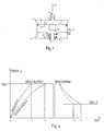
- FIG. 2 This behavior is shown schematically in the pressure / time diagram of FIG. 2.
- the diagram shows a pressure build-up phase in the left part and a pressure reduction phase in the right part.
- a line SOLL 1 is entered for a desired first desired consumer pressure
- in the right part there is also a parallel SOLL 2 to the time axis, which is at the end of the pressure reduction phase represents the desired second target consumer pressure.
- SHOULD 1 the value
- t2 - t1 is the lag.
- the person skilled in the art recognizes that the lag t sunflower - t3 is correspondingly in the pressure reduction phase.
- the lagging consumer pressure increase in the lag period t2 - t1 leads to an undesirably high slip of the vehicle wheel or requires additional measures to avoid it.
- the right part of the diagram illustrates this. The consequence in this case, however, instead of the high slip, is that the vehicle wheel is braked and air consumption increases.
- the invention is based on the object of improving a relay valve device of the type mentioned at the beginning with simple means such that it limits the lagging of the consumer pressure compared to the control pressure at least essentially to the unavoidable level for a given consumer group.
- the invention can be carried out with any suitable type of pressure medium.
- the pressure medium collected in the pressure relief chamber is fed back to a pressure medium source, i. H. clamped up to a supply pressure. If compressed air is used as pressure medium, the atmosphere can advantageously be used as a pressure relief space.
- the invention can be designed simply and inexpensively if the control pressure supply line, as taught in claims 3 and 4, is controlled by two shut-off valves or a shut-off valve and a changeover valve, each magnet-controlled.
- the invention is particularly suitable due to the magnetic control for use in connection with an electrical anti-lock system.
- An embodiment of the type mentioned above can be further developed in order to further reduce costs and or to create a compact design in that the throttle device is produced by suitably designing the flow resistance of one or the aforementioned solenoid-controlled valves.
- the relay valve device (1) shown in Fig. 1 has a control chamber (2) above a relay piston (6) and below the relay piston (6) an outlet chamber (10). Control pressure can be supplied to the control chamber (2) or removed from the control chamber (2) via a control pressure supply line (5, 3), which also includes a control connection (3).
- the outlet chamber (10) is connected on the one hand via a working connection (9) to a consumer circuit, not shown.
- the outlet chamber (10) can be connected via a valve device (8, 12, 13) to a storage chamber (11), which in turn is connected to a pressure medium source (not shown) via a storage connection (14), or to the atmosphere as a pressure relief chamber.
- the valve device (8, 12, 13) consists of an inlet valve (12, 13) and an outlet valve (8, 12).
- the valve device (8, 12, 13) has a displaceably guided hollow valve body (12) which, with a valve seat (13) fixed to the housing, the inlet valve (12, 13) and with a valve seat attached to the relay piston (6) (8) forms the outlet valve (8, 12).
- the relay piston (6) delimits the control chamber (2) with its one surface, which serves as a control surface (7), and the outlet chamber (10) with its other surface, which serves as a weighing surface (15).
- a throttle device (4) is arranged in the control pressure supply line (5, 3). This throttle device (4) is physically located in the control connection (3), but it can also be located at any other point in the Supply line (5, 3) can be arranged. There are applications in which the arrangement elsewhere is advantageous because of better accessibility for the purpose of adjusting the throttle device.
- the relay piston (6) If control pressure is discharged from the control chamber (2), the relay piston (6) is moved by the initially predominant consumer pressure over the weighing surface (15), the outlet valve (8, 12) opening and pressure medium from the consumer circuit and the outlet chamber (10) the hollow interior of the valve body (12) escapes into the atmosphere. When the balance on the relay piston (6) is restored by reducing the consumer pressure, the relay piston (6) and valve seat (8) return to the position determining the final position of the valve device (8, 12, 13).
- the pressure medium volume required for this must flow through the inlet valve (12, 13) or the outlet valve (8, 12).
- the cross section of the inlet valve (12, 13) or the outlet valve (8, 12), the volume of the consumer circuit and the flow resistance of at least one existing working line therefore determine the rate at which the consumer pressure builds up or decreases (in the consumer circuit and) in the outlet chamber (10 ).
- the throttle device (4) serves the rate of build-up or the rate of reduction of the control pressure in the control chamber to approach the rate of build-up or the rate of decrease of the consumer pressure in the outlet chamber (10) at least as closely as possible. Relative to the pressure / time diagram of FIG. 2 this means that in the pressure build-up phase and in the pressure reduction phase the control pressure curves are shifted towards longer times in such a way that they almost coincide with the respective consumer pressure curve. This substantially prevents the consumer pressure from lagging behind the control pressure.
- valve device (1) is to be used alternatively for consumer circuits of different volumes, it is advisable to match the dimensioning of the throttle device (4) to the consumer circuit with the largest volume.
- the time behavior in connection with the consumer groups with smaller volumes is adapted to that of the consumer group with the largest volume, i. H. deteriorated compared to the known relay valve device; however, this disadvantage is generally more than compensated for by the advantage of a uniform design of the relay valve device (1).
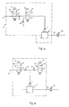
- valve 3 shows an embodiment of the valve device (1), in which the control pressure supply line (5, 3) is controlled by a solenoid-operated shut-off valve (20) and a solenoid-controlled changeover valve (25).
- (28, 32) denotes a consumer circuit symbolized by a brake cylinder (28) and a work line (32), the brake cylinder (28) also representing a plurality of brake cylinders and the work line (32) also representing a number of work lines.
- the shut-off valve (20) has a first position (23) and a second position (22). In the first position (23), in which it is returned when the associated magnet (21) is de-energized, the shut-off valve (20) releases the control line (5, 3). In its second position (22), in which it is placed by energizing the magnet (21), the shut-off valve (20) blocks the control line (5, 3).
- the changeover valve (25) has a first position (27) and a second position (26). In the first position (27), in which it is returned when the associated magnet (24) is de-energized, the changeover valve (25) releases the control line (5, 3). In its second position (26), in which it is placed by energizing its magnet (24), the changeover valve (25) blocks the control line (5, 3) and connects its downstream part and thus the control connection (3) and the control chamber (2) of the relay valve (1) with the atmosphere.
- the resetting can also be done in any other suitable way, for example by pressure.
- the throttle device designated here with (30, 29) consists of a throttle (30) assigned to the shut-off valve (20) and a throttle (29) assigned to the pressure relief outlet of the changeover valve, which is not described in any more detail.
- the chokes (30 and 29) can be dimensioned differently and / or adjusted differently for the reason mentioned above.
- the throttles are also symbolic of the fact that the throttle device can be produced in a manner not shown by suitable design of the flow resistance of the shut-off valve (20) and / or the changeover valve (25).
- the magnets (21 and 24) are de-energized and the control line (5, 3) is continuous.
- the control pressure is passed to the control connection (3) and to the control chamber (2) of the relay valve (1) and, as described above, converted into consumer pressure by the relay valve (1).
- a pressure holding position can be set by energizing the magnet (21) of the shut-off valve (20).
- the control line (5, 3) being shut off, the control pressure or a further increase in the latter into the control chamber (2) of the relay valve (1) cannot penetrate, with the result that consumer pressure does not build up or is present Consumer pressure does not continue to rise.
- the present exemplary embodiment can therefore be switched between the pressure build-up position, the pressure hold position and the pressure reduction position by excitation of only one of the magnets (21) or (24).
- This magnetically controlled changeover option can be evaluated using known methods for blocking protection of one or more vehicle wheels assigned to the consumer circuit.
- the suppression of the lag in consumer pressure at least essentially achieved with the invention compared to the control pressure is of great advantage.
- An enclosed line (31), shown in broken lines, indicates that the relay valve device (1) is described with the others Devices can be wholly or partially combined into one structural unit and that the other facilities or parts thereof can also form one or more structural units with one another.
- a first solenoid-controlled shut-off valve (40) and a second solenoid-controlled shut-off valve (46) serve to control the control pressure supply line.
- the second shut-off valve (46) is arranged parallel to the first shut-off valve (40) in the part of the control pressure feed line (5, 3) located downstream of the first shut-off valve (40).
- the second shut-off valve (46) has a first position (45) and a second position (47), which correspond to the positions of the first shut-off valve (40), but are functionally assigned to the associated magnet (44) in reverse.
- both magnets (21 and 44) are de-energized in the pressure build-up position.
- the magnet (44) To switch from the pressure holding position to the pressure reduction position, the magnet (44) must be excited in addition to the magnet (21). To switch from the pressure build-up position to the pressure reduction position, the simultaneous excitation of both magnets (21 and 44) is required. This requires a doubling of the excitation current and therefore means a disadvantage compared to the exemplary embodiment according to FIG. 3. This disadvantage is particularly serious if the consumer circuit is a trailer braking system, because the trailer is usually supplied by the electrical system of a towing vehicle via plug connections and long lines Due to the limited load capacity of the plug-in connections and the voltage losses caused by the plug-in connections and the long lines, the question of the power requirement is of particular importance, all the more so when considering the combination of several consecutive trailers as in some countries are common.
Description
Die Erfindung betrifft eine durch Steuerdruckzu- bzw. -abführung betätigbare Relaisventileinrichtung gemäß dem Oberbegriff des Patentanspruchs 1.The invention relates to a relay valve device which can be actuated by supplying or discharging control pressure.
Eine derartige Relaisventileinrichtung ist aus der DE-A-2 500 483 bekannt. Diese weist oberhalb eines aus einer Membran gebildeten Relaiskolbens eine Steuerkammer und unterhalb des Relaiskolbens eine Auslaßkammer auf. Über eine Steuerdruckzuleitung, welche auch einen Steueranschluß umfaßt, ist Steuerdruck der Steuerkammer zuführbar bzw. aus der Steuerkammer abführbar. Die Auslaßkammer ist einerseits über einen Arbeitsanschluß mit einem Verbraucherkreis verbunden. Andererseits ist die Auslaßkammer über ein Einlaßventil einer Ventileinrichtung und über einen Vorratsanschluß mit einer Druckmittelquelle oder über ein Auslaßventil der Ventileinrichtung und über einen Druckentlastungsausgang mit einem Druckentlastungsraum verbindbar. Betätigt wird die bekannte Ventileinrichtung durch Zuführung bzw. Abführung von Steuerdruck in die bzw. aus der Steuerkammer über eine Drosseleinrichtung, wodurch der Relaiskolben seinerseits die Ventileinrichtung betätigt. Die Drosseleinrichtung dient der Einstellung der Belüftungszeit des Verbraucherkreises. Mit der bekannten Relaisventileinrichtung wird infolge der Ausbildung des Relaiskolbens nach Abschluß einer Betätigung ein dem Steuerdruck im wesentlichen gleicher Verbraucherdruck in der Auslaßkammer und im Verbraucherkreis erzielt. Die Erfindung soll aber auch eine Ausbildung der Relaisventileinrichtung erfassen, mit der durch entsprechende Gestaltung des Relaiskolbens ein gegenüber dem Steuerdruck übersetzter oder untersetzter Verbraucherdruck erzielt wird. Für eine derartige Ausbildung gelten die folgenden Ausführungen entsprechend.Such a relay valve device is known from DE-A-2 500 483. This has a control chamber above a relay piston formed from a membrane and an outlet chamber below the relay piston. Via a control pressure supply line, which also includes a control connection, control pressure can be supplied to the control chamber or can be removed from the control chamber. The outlet chamber is connected to a consumer circuit via a working connection. On the other hand, the outlet chamber can be connected to a pressure medium source via an inlet valve of a valve device and via a supply connection or via an outlet valve of the valve device and via a pressure relief outlet to a pressure relief space. The known valve device is actuated by supplying or discharging control pressure into or out of the control chamber via a throttle device, as a result of which the relay piston in turn actuates the valve device. The throttle device is used to set the ventilation time of the consumer circuit. With the known relay valve device, a control pressure which is essentially the same as the control pressure in the outlet chamber and in the consumer circuit is due to the formation of the relay piston after completion of an operation achieved. However, the invention is also intended to detect an embodiment of the relay valve device with which a consumer pressure which is translated or reduced compared to the control pressure is achieved by appropriate design of the relay piston. The following statements apply accordingly to such training.
Im folgenden sind die Begriffe "Volumen des Verbraucherkreises" bzw. "Volumen der Steuerkammer" als die Volumina der etwa zugehörigen Arbeitsleitungen und der Auslaßkammer bzw. das Volumen der Steuerdruckzuleitung enthaltend zu verstehen. Es wird auch unterstellt,, daß die etwa vorhandene wenigstens eine Arbeitsleitung in ihrem Durchflußwiderstand so ausgelegt ist, daß der Verbraucherdruck in Auslaßkammer des Relaisventils und Verbraucherkreis bei voll geöffneter Ventileinrichtung stets im wesentlichen gleich ist. In der Regel ist das Volumen des Verbraucherkreises wesentlich größer als das Volumen der Steuerkammer. Deshalb und wegen des Durchflußwiderstands der etwa vorhandenen Arbeitsleitungen stellt sich bei der bekannten Relaisventileinrichtung der dem Steuerdruck entsprechende Verbraucherdruck gegenüber dem Steuerdruck verzögert ein, mit anderen Worten: Der Verbraucherdruck eilt dem Steuerdruck (zeitlich) nach.In the following, the terms “volume of the consumer circuit” or “volume of the control chamber” are to be understood as containing the volumes of the work lines and the outlet chamber or the volume of the control pressure supply line. It is also assumed that the at least one working line, if any, is designed in terms of its flow resistance so that the consumer pressure in the outlet chamber of the relay valve and the consumer circuit is always essentially the same when the valve device is fully open. As a rule, the volume of the consumer circuit is significantly larger than the volume of the control chamber. For this reason and because of the flow resistance of the existing working lines, in the known relay valve device the consumer pressure corresponding to the control pressure is delayed in relation to the control pressure, in other words: the consumer pressure lags behind the control pressure (in time).
In dem Druck/Zeit-Schaubild der Fig. 2 ist dieses Verhalten schematisch dargestellt. Das Schaubild zeigt im linken Teil eine Druckaufbauphase und im rechten Teil eine Druckabbauphase. Parallel zur Zeitachse ist eine Linie SOLL₁ für einen angestrebten ersten SOLL-Verbraucherdruck eingetragen, im rechten Teil ist zusätzlich eine Parallele SOLL₂ zur Zeitachse, die einen am Abschluß der Druckabbauphase angestrebten zweiten SOLL-Verbraucherdruck darstellt, eingetragen. Es ist ersichtlich, daß in der Druckaufbauphase der Steuerdruck den Wert SOLL₁ zu einem Zeitpunkt t₁ erreicht, während der Verbraucherdruck diesen Wert erst zu einem späteren Zeitpunkt t₂ erreicht. t₂ - t₁ ist die Nacheilung. Der Fachmann erkennt, daß entsprechend in der Druckabbauphase die Nacheilung t₄ - t₃ beträgt.This behavior is shown schematically in the pressure / time diagram of FIG. 2. The diagram shows a pressure build-up phase in the left part and a pressure reduction phase in the right part. Parallel to the time axis, a
Nun gibt es Einsatzfälle, in denen die erwähnte Nacheilung Probleme schafft. Ein solcher Einsatzfall ist beispielsweise gegeben, wenn der Verbraucherkreis aus einem oder mehreren Bremszylindern einer blockiergeschützten Fahrzeug-Bremsanlage besteht. Nehmen wir an, daß der Verbraucherdruck, der bei t₁ erreicht ist, das dem Verbraucherkreis zugeordnete Fahrzeugrad, wobei "Fahrzeugrad" auch mehrere Fahrzeugräder bedeuten kann, in die Nähe seiner Blockiergrenze bringt. Dann gibt die Blockierschutzanlage in diesem Zeitpunkt ein Signal, aufgrund dessen die Steuerdruckzuführung abbricht. Trotz unterbrochener Steuerdruckzuführung steigt nun der Verbraucherdruck weiter an, bis er im Zeitpunkt t₂ den Wert SOLL₁ erreicht. Der nacheilende Verbraucherdruckanstieg im Nacheilungszeitraum t₂ - t₁ führt zu einem unerwünscht hohen Schlupf des Fahrzeugrades bzw. bedingt zu dessen Vermeidung zusätzliche Maßnahmen. Entsprechendes gilt, wenn das Fahrzeugrad bei anstehendem ersten SOLL-Verbraucherdruck an seine Blockiergrenze gerät und die Blockierschutzanlage eine Druckabbauphase einleitet. Der rechte Teil des Schaubilds veranschaulicht dies. Die Folge ist in diesem Fall jedoch statt des hohen Schlupfes, daß das Fahrzeugrad unterbremst wird und der Luftverbrauch steigt.Now there are cases in which the mentioned lag creates problems. Such an application is given, for example, if the consumer circuit consists of one or more brake cylinders of an anti-lock vehicle brake system. Let us assume that the consumer pressure, which is reached at
Der Erfindung liegt nun die Aufgabe zugrunde, eine Relaisventileinrichtung der eingangs genannten Art mit einfachen Mitteln so zu verbessern, daß sie bei gegebenem Verbraucherkreis die Nacheilung des Verbraucherdrucks gegenüber dem Steuerdruck wenigstens im wesentlichen auf das unvermeidbare Maß beschränkt.The invention is based on the object of improving a relay valve device of the type mentioned at the beginning with simple means such that it limits the lagging of the consumer pressure compared to the control pressure at least essentially to the unavoidable level for a given consumer group.
Diese Aufgabe wird durch die im Patentanspruch 1 angegebene Erfindung gelöst. Weiterbildungen und vorteilhafte Ausgestaltungen sind in den Unteransprüchen angegeben.This object is achieved by the invention specified in
Die Erfindung läßt sich mit jeder geeigneten Art Druckmittel ausführen. Üblicherweise wird das im Druckentlastungsraum gesammelte Druckmittel wieder einer Druckmittelquelle zugeführt, d. h. auf einen Vorratsdruck hochgespannt. Im Falle der Verwendung von Druckluft als Druckmittel läßt sich in vorteilhafter Weise die Atmosphäre als Druckentlastungsraum heranziehen.The invention can be carried out with any suitable type of pressure medium. Usually, the pressure medium collected in the pressure relief chamber is fed back to a pressure medium source, i. H. clamped up to a supply pressure. If compressed air is used as pressure medium, the atmosphere can advantageously be used as a pressure relief space.
Die Erfindung läßt sich einfach und kostengünstig ausbilden, wenn die Steuerdruckzuleitung, wie in den Patentansprüchen 3 und 4 gelehrt wird, durch zwei Absperrventile oder ein Absperrventil und ein Umschaltventil, jeweils magnetgesteuert, kontrolliert wird.The invention can be designed simply and inexpensively if the control pressure supply line, as taught in
In einer derartigen Ausgestaltung ist die Erfindung aufgrund der Magnetsteuerung zum Einsatz in Verbindung mit einer elektrischen Blockierschutzanlage besonders geeignet.In such an embodiment, the invention is particularly suitable due to the magnetic control for use in connection with an electrical anti-lock system.
Eine Ausgestaltung der vorstehend erwähnten Art kann zur weiteren Kostenminderung undoder zur Schaffung einer kompakten Bauweise dadurch fortgebildet werden, daß die Drosseleinrichtung durch geeignete Auslegung des Durchlflußwiderstands eines oder der erwähnten magnetgesteuerten Ventile hergestellt wird.An embodiment of the type mentioned above can be further developed in order to further reduce costs and or to create a compact design in that the throttle device is produced by suitably designing the flow resistance of one or the aforementioned solenoid-controlled valves.
Die Erfindung wird nachstehend unter Angabe weiterer Vorteile und unter durchgehender Verwendung gleicher Bezugszeichen für Bauteile mit gleichen Funktionen in Zeichnungen dargestellt.The invention is shown below in the drawings with the specification of further advantages and using the same reference numerals for components with the same functions.
Es zeigen:
- Fig. 1
- schematisch eine Relaisventileinrichtung,
- Fig. 2
- ein Druck/Zeit-Schaubild,
- Fig. 3
- eine Relaisventileinrichtung mit magnetgesteuerter Steuerdruckzu- bzw. -abführung,
- Fig. 4
- eine andere Relaisventileinrichtung mit magnetgesteuerter Druckzu- bzw. -abführung.
- Fig. 1
- schematically a relay valve device,
- Fig. 2
- a pressure / time diagram,
- Fig. 3
- a relay valve device with solenoid-controlled control pressure supply and discharge,
- Fig. 4
- another relay valve device with magnetically controlled pressure supply or discharge.
Alle Ausführungsbeispiele sind in Verbindung mit Druckluft als Druckmittel beschrieben, sie stehen aber auch bei entsprechender Anwendung für den Einsatz mit anderen Druckmitteln.All of the exemplary embodiments are described in connection with compressed air as the pressure medium, but they also stand for use with other pressure media when used accordingly.
Die in Fig. 1 dargestellte Relaisventileinrichtung (1) weist oberhalb eines Relaiskolbens (6) eine Steuerkammer (2) und unterhalb des Relaiskolbens (6) eine Auslaßkammer (10) auf. Über eine Steuerdruckzuleitung (5, 3), welche auch einen Steueranschluß (3) umfaßt, ist Steuerdruck der Steuerkammer (2) zuführbar bzw. aus der Steuerkammer (2) abführbar.The relay valve device (1) shown in Fig. 1 has a control chamber (2) above a relay piston (6) and below the relay piston (6) an outlet chamber (10). Control pressure can be supplied to the control chamber (2) or removed from the control chamber (2) via a control pressure supply line (5, 3), which also includes a control connection (3).
Die Auslaßkammer (10) ist einerseits über einen Arbeitsanschluß (9) mit einem nicht dargestellten Verbraucherkreis verbunden. Andererseits ist die Auslaßkammer (10) über eine Ventileinrichtung (8, 12, 13) mit einer Vorratskammer (11), die ihrerseits über einen Vorratsanschluß (14) mit einer nicht dargestellten Druckmittelquelle verbunden ist, oder mit der Atmosphäre als Druckentlastungsraum verbindbar.The outlet chamber (10) is connected on the one hand via a working connection (9) to a consumer circuit, not shown. On the other hand, the outlet chamber (10) can be connected via a valve device (8, 12, 13) to a storage chamber (11), which in turn is connected to a pressure medium source (not shown) via a storage connection (14), or to the atmosphere as a pressure relief chamber.
Die Ventileinrichtung (8, 12, 13) besteht aus einem Einlaßventil (12, 13) und einem Auslaßventil (8, 12). Zur Bildung der Ventile weist die Ventileinrichtung (8, 12, 13) einen verschiebbar geführten hohlen Ventilkörper (12) auf, der mit einem gehäusefesten Ventilsitz (13) das Einlaßventil (12, 13) und mit einem an dem Relaiskolben (6) angebrachten Ventilsitz (8) das Auslaßventil (8, 12) bildet.The valve device (8, 12, 13) consists of an inlet valve (12, 13) and an outlet valve (8, 12). To form the valves, the valve device (8, 12, 13) has a displaceably guided hollow valve body (12) which, with a valve seat (13) fixed to the housing, the inlet valve (12, 13) and with a valve seat attached to the relay piston (6) (8) forms the outlet valve (8, 12).
Der Relaiskolben (6) begrenzt mit seiner einen Fläche, die als Steuerfläche (7) dient, die Steuerkammer (2) und mit seiner anderen Fläche, die als Wiegefläche (15) dient, die Auslaßkammer (10).The relay piston (6) delimits the control chamber (2) with its one surface, which serves as a control surface (7), and the outlet chamber (10) with its other surface, which serves as a weighing surface (15).
In der Steuerdruckzuleitung (5, 3) ist eine Drosseleinrichtung (4) angeordnet. Körperlich befindet sich diese Drosseleinrichtung (4) in dem Steueranschluß (3), sie kann aber auch an jeder anderen Stelle der Zuleitung (5, 3) angeordnet sein. Es gibt Einsatzfälle, in denen die Anordnung an anderer Stelle wegen etwa besserer Zugänglichkeit zum Zwecke des Einstellens der Drosseleinrichtung vorteilhaft ist.A throttle device (4) is arranged in the control pressure supply line (5, 3). This throttle device (4) is physically located in the control connection (3), but it can also be located at any other point in the Supply line (5, 3) can be arranged. There are applications in which the arrangement elsewhere is advantageous because of better accessibility for the purpose of adjusting the throttle device.
Für die folgende Funktionsbeschreibung sei zunächst angenommen, daß in der Steuerkammer (2), im Verbraucherkreis und in der Auslaßkammer (10) Atmosphärendruck herrsche. In diesem Zustand sind das Einlaßventil (12, 13) durch eine nicht näher bezeichnete Rückstellfeder geschlossen und das Auslaßventil (8, 12) geöffnet. Ein der Steuerkammer (2) zugeführter Steuerdruck beaufschlagt die Steuerfläche (7) des Relaiskolbens (6) und verschiebt diesen unter Mitnahme des Ventilsitzes (8). Im Verlaufe der Verschiebung setzt der Ventilsitz (8) auf den Doppelventilkörper (12) auf und nimmt diesen mit. Dabei werden das Auslaßventil (8, 12) geschlossen und das Einlaßventil (12, 13) geöffnet. Hat sich im Verbraucherkreis und in der Auslaßkammer (10) ein Verbraucherdruck aufgebaut, der über die Wiegefläche (15) den Relaiskolben (6) gegenüber dem auf der Steuerfläche (7) wirkenden Steuerdruck ins Gleichgewicht bringt, so bewegt sich der Relaiskolben (6) soweit zurück, daß gleichzeitig das Auslaßventil (8, 12) und das Einlaßventil (12, 13) geschlossen sind. Dieser Zustand stellt eine Abschlußstellung der Ventileinrichtung (8, 12, 13) dar. Stehen der Verbraucherkreis und die Auslaßkammer (10) bereits unter Verbraucherdruck und wird zum Zwecke von dessen Erhöhung ein höherer Steuerdruck zugeführt, so wirken der Relaiskolben (6) und die Ventileinrichtung (8, 12, 13), ausgehend von der Abschlußstellung, entsprechend der soeben beschriebenen Weise zusammen.For the following functional description, it is initially assumed that there is atmospheric pressure in the control chamber (2), in the consumer circuit and in the outlet chamber (10). In this state, the inlet valve (12, 13) is closed by a return spring, not specified, and the outlet valve (8, 12) is opened. A control pressure supplied to the control chamber (2) acts on the control surface (7) of the relay piston (6) and moves it, taking the valve seat (8) with it. In the course of the displacement, the valve seat (8) rests on the double valve body (12) and takes it along. The outlet valve (8, 12) is closed and the inlet valve (12, 13) is opened. Has a consumer pressure built up in the consumer circuit and in the outlet chamber (10), which brings the relay piston (6) into balance with the control pressure acting on the control surface (7) via the weighing surface (15), the relay piston (6) moves as far back that the outlet valve (8, 12) and the inlet valve (12, 13) are closed at the same time. This state represents a final position of the valve device (8, 12, 13). If the consumer circuit and the outlet chamber (10) are already under consumer pressure and a higher control pressure is supplied for the purpose of increasing it, the relay piston (6) and the valve device act (8, 12, 13), starting from the final position, together in the manner just described.
Wird Steuerdruck aus der Steuerkammer (2) abgeführt, so wird der Relaiskolben (6) von dem zunächst überwiegenden Verbraucherdruck über die Wiegefläche (15) bewegt, wobei sich das Auslaßventil (8, 12) öffnet und Druckmittel aus Verbraucherkreis und Auslaßkammer (10) über den hohlen Innenraum des Ventilkörpers (12) in die Atmosphäre entweicht. Bei Wiederherstellung des Gleichgewichts am Relaiskolben (6) durch Abbau des Verbraucherdrucks kehren Relaiskolben (6) und Ventilsitz (8) in die die Abschlußstellung der Ventileinrichtung (8, 12, 13) bestimmende Lage zurück.If control pressure is discharged from the control chamber (2), the relay piston (6) is moved by the initially predominant consumer pressure over the weighing surface (15), the outlet valve (8, 12) opening and pressure medium from the consumer circuit and the outlet chamber (10) the hollow interior of the valve body (12) escapes into the atmosphere. When the balance on the relay piston (6) is restored by reducing the consumer pressure, the relay piston (6) and valve seat (8) return to the position determining the final position of the valve device (8, 12, 13).
Zum Aufbau bzw. zum Abbau des Verbraucherdrucks im Verbraucherkreis muß das dazu erforderliche Druckmittelvolumen das Einlaßventil (12, 13) bzw. das Auslaßventil (8, 12) durchströmen. Der Querschnitt des Einlaßventils (12, 13) bzw. des Auslaßventils (8, 12), das Volumen des Verbraucherkreises und der Durchflußwiderstand wenigstens einer etwa vorhandenen Arbeitsleitung bestimmen daher die Aufbaugeschwindigkeit bzw. Abbaugeschwindigkeit des Verbraucherdrucks (im Verbraucherkreis und) in der Auslaßkammer (10). Die Drosseleinrichtung (4) dient dazu, durch Begrenzung der Nacheilung des Verbraucherdruckes gegenüber dem Steuerdruck auf ein Maß, das wenigstens angenähert gerade das volle Öffnen der Ventileinrichtung (8, 12, 13) gewährleistet, die Aufbaugeschwindigkeit bzw. die Abbaugeschwindigkeit des Steuerdrucks in der Steuerkammer der Aufbaugeschwindigkeit bzw. der Abbaugeschwindigkeit des Verbraucherdrucks in der Auslaßkammer (10) wenigstens angenähert so weit wie möglich anzunähern. Bezogen auf das Druck/Zeit-Schaubild der Fig. 2 bedeutet dies, daß in der Druckaufbauphase und in der Druckabbauphase die Steuerdruckkurven derart in Richtung längerer Zeiten verschoben werden, daß sie mit der jeweiligen Verbraucherdruckkurve nahezu zusammenfallen. Dadurch wird das Auftreten einer Nacheilung des Verbraucherdrucks gegenüber dem Steuerdruck im wesentlichen vermieden.To build up or reduce the consumer pressure in the consumer circuit, the pressure medium volume required for this must flow through the inlet valve (12, 13) or the outlet valve (8, 12). The cross section of the inlet valve (12, 13) or the outlet valve (8, 12), the volume of the consumer circuit and the flow resistance of at least one existing working line therefore determine the rate at which the consumer pressure builds up or decreases (in the consumer circuit and) in the outlet chamber (10 ). By restricting the lagging of the consumer pressure compared to the control pressure to a level that at least approximately ensures the full opening of the valve device (8, 12, 13), the throttle device (4) serves the rate of build-up or the rate of reduction of the control pressure in the control chamber to approach the rate of build-up or the rate of decrease of the consumer pressure in the outlet chamber (10) at least as closely as possible. Relative to the pressure / time diagram of FIG. 2 this means that in the pressure build-up phase and in the pressure reduction phase the control pressure curves are shifted towards longer times in such a way that they almost coincide with the respective consumer pressure curve. This substantially prevents the consumer pressure from lagging behind the control pressure.
Da der Abbau des Verbraucherdrucks in der Regel über einen großen Querschnitt ((Hohlraum des Ventilkörpers (12)) und auf kürzerem Wege erfolgt, ist die im Vorstehenden definierte Nacheilung in der Druckabbauphase tendenziell geringer als in der Druckaufbauphase. Diese Eigenschaft kann im Sinne einer Verbesserung des Zeitverhaltens ausgewertet werden, indem die Drosseleinrichtung (4) in Strömungsrichtung des abgeführten Steuerdrucks für einen geringeren Durchflußwiderstand bemessen wird.Since the reduction in consumer pressure generally takes place over a large cross-section ((cavity of the valve body (12)) and is shorter, the lag defined in the foregoing tends to be lower in the pressure reduction phase than in the pressure build-up phase. This property can be an improvement of the time behavior can be evaluated by dimensioning the throttle device (4) in the flow direction of the removed control pressure for a lower flow resistance.
Soll die Ventileinrichtung (1) alternativ für Verbraucherkreise unterschiedlicher Volumina eingesetzt werden, so empfiehlt es sich, die Bemessung der Drosseleinrichtung (4) auf den Verbraucherkreis mit dem größten Volumen abzustimmen. In diesem Fall wird das Zeitverhalten in Verbindung mit den Verbraucherkreisen mit kleineren Volumina demjenigen des Verbraucherkreises mit dem größten Volumen angepaßt, d. h. gegenüber der bekannten Relaisventileinrichtung verschlechtert; dieser Nachteil wird jedoch in der Regel durch den Vorteil einer einheitlichen Ausbildung der Relaisventileinrichtung (1) mehr als ausgeglichen.If the valve device (1) is to be used alternatively for consumer circuits of different volumes, it is advisable to match the dimensioning of the throttle device (4) to the consumer circuit with the largest volume. In this case, the time behavior in connection with the consumer groups with smaller volumes is adapted to that of the consumer group with the largest volume, i. H. deteriorated compared to the known relay valve device; however, this disadvantage is generally more than compensated for by the advantage of a uniform design of the relay valve device (1).
Fig. 3 zeigt eine Ausgestaltung der Ventileinrichtung (1), in der die Steuerdruckzuleitung (5, 3) durch ein magnetgesteuertes Absperrventil (20) und ein magnetgesteuertes Umschaltventil (25) kontrolliert wird.3 shows an embodiment of the valve device (1), in which the control pressure supply line (5, 3) is controlled by a solenoid-operated shut-off valve (20) and a solenoid-controlled changeover valve (25).
Mit (28, 32) ist in diesem Falle ein durch einen Bremszylinder (28) und eine Arbeitsleitung (32) symbolisierter Verbraucherkreis bezeichnet, wobei der Bremszylinder (28) auch für mehrere Bremszylinder und die Arbeitsleitung (32) auch für mehrere Arbeitsleitungen stehen.In this case, (28, 32) denotes a consumer circuit symbolized by a brake cylinder (28) and a work line (32), the brake cylinder (28) also representing a plurality of brake cylinders and the work line (32) also representing a number of work lines.
Das Abschaltventil (20) weist eine erste Stellung (23) und eine zweite Stellung (22) auf. In der ersten Stellung (23), in die es bei entregtem zugehörigen Magneten (21) zurückgestellt wird, gibt das Absperrventil (20) die Steuerleitung (5, 3) frei. In seiner zweiten Stellung (22), in die es durch Erregung des Magneten (21) gestellt wird, sperrt das Absperrventil (20) die Steuerleitung (5, 3).The shut-off valve (20) has a first position (23) and a second position (22). In the first position (23), in which it is returned when the associated magnet (21) is de-energized, the shut-off valve (20) releases the control line (5, 3). In its second position (22), in which it is placed by energizing the magnet (21), the shut-off valve (20) blocks the control line (5, 3).
Das Umschaltventil (25) weist eine erste Stellung (27) und eine zweite Stellung (26) auf. In der ersten Stellung (27), in die es bei entregtem zugehörigen Magneten (24) zurückgestellt wird, gibt das Umschaltventil (25) die Steuerleitung (5, 3) frei. In seiner zweiten Stellung (26), in die es durch Erregung seines Magneten (24) gestellt wird, sperrt das Umschaltventil (25) die Steuerleitung (5, 3) und verbindet deren stromabwärts gelegenen Teil und damit den Steueranschluß (3) sowie die Steuerkammer (2) des Relaisventils (1) mit der Atmosphäre.The changeover valve (25) has a first position (27) and a second position (26). In the first position (27), in which it is returned when the associated magnet (24) is de-energized, the changeover valve (25) releases the control line (5, 3). In its second position (26), in which it is placed by energizing its magnet (24), the changeover valve (25) blocks the control line (5, 3) and connects its downstream part and thus the control connection (3) and the control chamber (2) of the relay valve (1) with the atmosphere.
Für die Rückstellung des Absperrventils (20) und des Umschaltventils (25) in die jeweils erste Stellung (23 bzw. 27) sind Federn vorgesehen. Die Rückstellung kann aber auch auf jeder andere geeignete Weise erfolgen, beispielsweise durch einen Druck.Springs are provided to reset the shut-off valve (20) and the changeover valve (25) to the first position (23 or 27). The resetting can also be done in any other suitable way, for example by pressure.
Die hier mit (30, 29) bezeichnete Drosseleinrichtung besteht aus einer dem Abschaltventil (20) zugeordneten Drossel (30) und einer dem nicht näher bezeichneten Druckentlastungsausgang des Umschaltventils zugeordneten Drossel (29). Die Drosseln (30 bzw. 29) können aus dem weiter oben erwähnten Grunde unterschiedlich bemessen und/oder unterschiedlich einstellbar sein. Die Drosseln stehen auch symbolisch dafür, daß in nicht näher dargestellter Weise die Drosseleinrichtung durch geeignete Auslegung des Durchflußwiderstands des Absperrventils (20) und/oder des Umschaltventils (25) herstellbar ist.The throttle device designated here with (30, 29) consists of a throttle (30) assigned to the shut-off valve (20) and a throttle (29) assigned to the pressure relief outlet of the changeover valve, which is not described in any more detail. The chokes (30 and 29) can be dimensioned differently and / or adjusted differently for the reason mentioned above. The throttles are also symbolic of the fact that the throttle device can be produced in a manner not shown by suitable design of the flow resistance of the shut-off valve (20) and / or the changeover valve (25).
Im Normalbetrieb sind die Magnete (21 und 24) entregt und die Steuerleitung (5, 3) durchgängig. In dieser Druckaufbaustellung wird der Steuerdruck zum Steueranschluß (3) und zur Steuerkammer (2) des Relaisventils (1) durchgelassen und von dem Relaisventil (1), wie oben beschrieben, in Verbraucherdruck umgesetzt.In normal operation, the magnets (21 and 24) are de-energized and the control line (5, 3) is continuous. In this pressure build-up position, the control pressure is passed to the control connection (3) and to the control chamber (2) of the relay valve (1) and, as described above, converted into consumer pressure by the relay valve (1).
Durch Erregung des Magneten (21) des Absperrventils (20) ist eine Druckhaltestellung einstellbar. In dieser kann infolge der Absperrung der Steuerleitung (5, 3) der Steuerdruck bzw. ein weiterer Anstieg desselben in die Steuerkammer (2) des Relaisventils (1) nicht durchdringen mit der Folge, daß sich auch ein Verbraucherdruck nicht aufbaut bzw. vorhandener Verbraucherdruck nicht weiter steigt.A pressure holding position can be set by energizing the magnet (21) of the shut-off valve (20). As a result of the control line (5, 3) being shut off, the control pressure or a further increase in the latter into the control chamber (2) of the relay valve (1) cannot penetrate, with the result that consumer pressure does not build up or is present Consumer pressure does not continue to rise.
Durch Erregung des Magneten (24) des Umschaltventils (25) ist eine Umstellung aus der Druckaufbaustellung in eine Druckabbaustellung möglich. Aus der Druckhaltestellung ist eine Umstellung in die Druckabbaustellung durch gleichzeitiges Entregen des Magneten (21) und Erregen des Magneten (24) möglich. In der Druckabbaustellung ist die Steuerleitung (5, 3) durch das Umschaltventil (25) gesperrt, gleichzeitig sind aber ihr stromabwärts des Umschaltventils (25) gelegener Teil und damit die Steuerkammer (2) des Relaisventils (1) mit der Atmosphäre verbunden. Aufgrund des dadurch hervorgerufenen Steuerdruckabfalls bewirkt das Relaisventil (1) in der oben beschriebenen Weise einen entsprechenden Abfall des Verbraucherdrucks.By energizing the magnet (24) of the changeover valve (25), a change from the pressure build-up position to a pressure reduction position is possible. From the pressure maintenance position, a switch to the pressure reduction position is possible by simultaneously de-energizing the magnet (21) and energizing the magnet (24). In the pressure reduction position, the control line (5, 3) is blocked by the changeover valve (25), but at the same time its part located downstream of the changeover valve (25) and thus the control chamber (2) of the relay valve (1) are connected to the atmosphere. Due to the resulting drop in control pressure, the relay valve (1) causes a corresponding drop in consumer pressure in the manner described above.
Das vorliegende Ausführungsbeispiel ist also durch Erregung nur jeweils eines der Magneten (21) bzw. (24) zwischen der Druckaufbaustellung, der Druckhaltestellung und der Druckabbaustellung umstellbar. Diese magnetgesteuerte Umstellmöglichkeit kann nach bekannten Verfahren zum Blockierschutz eines oder mehrerer dem Verbraucherkreis zugeordneter Fahrzeugräder ausgewertet werden. Dabei ist, wie aus der Beschreibungseinleitung hervorgeht, die mit der Erfindung wenigstens im wesentlichen erzielte Unterdrückung der Nacheilung des Verbraucherdrucks gegenüber dem Steuerdruck von großem Vorteil.The present exemplary embodiment can therefore be switched between the pressure build-up position, the pressure hold position and the pressure reduction position by excitation of only one of the magnets (21) or (24). This magnetically controlled changeover option can be evaluated using known methods for blocking protection of one or more vehicle wheels assigned to the consumer circuit. Here, as can be seen from the introduction to the description, the suppression of the lag in consumer pressure at least essentially achieved with the invention compared to the control pressure is of great advantage.
Durch eine mit (31) bezeichnete, gestrichelt dargestellte Umfassungslinie ist angedeutet, daß die Relaisventileinrichtung (1) mit den anderen beschriebenen Einrichtungen ganz oder teilweise zu einer Baueinheit vereinigt sein kann und daß auch die anderen Einrichtungen bzw. Teile davon untereinander eine oder mehrere Baueinheiten bilden können.An enclosed line (31), shown in broken lines, indicates that the relay valve device (1) is described with the others Devices can be wholly or partially combined into one structural unit and that the other facilities or parts thereof can also form one or more structural units with one another.
Es liegt auf der Hand, daß, sofern die Anordnung in Reihe erhalten bleibt, die Reihenfolge des Absperrventils (20) und des Umschaltventils (25) auch verändert werden kann.It is obvious that, if the arrangement remains in line, the sequence of the shut-off valve (20) and the changeover valve (25) can also be changed.
Für das Ausführungsbeispiel nach der Fig. 4 gelten, soweit nachstehend nichts Abweichendes gesagt wird, die zu den vorherigen Ausführungsbeispielen gegebenen Erläuterungen wenigstens entsprechend mit.Unless otherwise stated below, the explanations given for the previous exemplary embodiments also apply at least correspondingly to the exemplary embodiment according to FIG. 4.
Zur Kontrolle der Steuerdruckzuleitung dienen hier ein erstes magnetgesteuertes Absperrventil (40) und ein zweites magnetgesteuertes Absperrventil (46). Das zweite Absperrventil (46) ist parallel zum ersten Absperrventil (40) in dem stromabwärts des ersten Absperrventils (40) gelegenen Teil der Steuerdruckzuleitung (5, 3) angeordnet.A first solenoid-controlled shut-off valve (40) and a second solenoid-controlled shut-off valve (46) serve to control the control pressure supply line. The second shut-off valve (46) is arranged parallel to the first shut-off valve (40) in the part of the control pressure feed line (5, 3) located downstream of the first shut-off valve (40).
Der Aufbau des ersten Absperrventils (40) ist, wie durch gleiche Bezugszeichen für dessen Magnet und Stellungen angedeutet ist, mit dem Aufbau des Absperrventils (20) identisch.The construction of the first shut-off valve (40), as indicated by the same reference numerals for its magnet and positions, is identical to the construction of the shut-off valve (20).
Das zweite Absperrventil (46) weist eine erste Stellung (45) und eine zweite Stellung (47) auf, die den Stellungen des ersten Absperrventils (40) entsprechen, dem zugehörigen Magneten (44) funktionsmäßig jedoch umgekehrt zugeordnet sind.The second shut-off valve (46) has a first position (45) and a second position (47), which correspond to the positions of the first shut-off valve (40), but are functionally assigned to the associated magnet (44) in reverse.
Auch hier sind in der Druckaufbaustellung beide Magnete (21 und 44) entregt.Here, too, both magnets (21 and 44) are de-energized in the pressure build-up position.
Die Umstellung in die Druckhaltestellung geschieht wieder durch Erregung des Magneten (21).The changeover to the pressure holding position is again done by energizing the magnet (21).
Zur Umstellung aus der Druckhaltestellung in die Druckabbaustellung ist jedoch zusätzlich zum Magneten (21) die Erregung des Magneten (44) erforderlich. Zur Umstellung aus der Druckaufbaustellung in die Druckabbaustellung ist die gleichzeitige Erregung beider Magneten (21 und 44) erforderlich. Das bedingt eine Verdoppelung des Erregerstroms und bedeutet deshalb einen Nachteil gegenüber dem Ausführungsbeispiel nach Fig. 3. Dieser Nachteil ist insbesondere gravierend, wenn der Verbraucherkreis eine Anhänger-Bremsanlage ist, weil der Anhänger üblicherweise über Steckverbindungen und lange Leitungen von der elektrischen Anlage eines Zugfahrzeugs versorgt wird, wobei infolge der begrenzten Belastbarkeit der Steckverbindungen und der durch die Steckverbindungen und die langen Leitungen verursachten Spannungsverluste die Frage des Strombedarfs von besonderer Bedeutung ist, dies um so mehr, wenn an Lastzüge mit mehreren aufeinander folgenden Anhängern gedacht wird, wie sie in einigen Ländern üblich sind.To switch from the pressure holding position to the pressure reduction position, the magnet (44) must be excited in addition to the magnet (21). To switch from the pressure build-up position to the pressure reduction position, the simultaneous excitation of both magnets (21 and 44) is required. This requires a doubling of the excitation current and therefore means a disadvantage compared to the exemplary embodiment according to FIG. 3. This disadvantage is particularly serious if the consumer circuit is a trailer braking system, because the trailer is usually supplied by the electrical system of a towing vehicle via plug connections and long lines Due to the limited load capacity of the plug-in connections and the voltage losses caused by the plug-in connections and the long lines, the question of the power requirement is of particular importance, all the more so when considering the combination of several consecutive trailers as in some countries are common.
Im übrigen gelten die zu einzelnen Ausführungsbeispielen gegebenen Erläuterungen, soweit aus ihnen nichts anderes hervorgeht, für die anderen Ausführungsbeispiele wenigstens entsprechend mit.Otherwise, unless otherwise stated, the explanations given for individual exemplary embodiments also apply accordingly to the other exemplary embodiments.
Der Fachmann erkennt, daß sich der Schutzbereich der vorliegenden Erfindung nicht in den Ausführungsbeispielen erschöpft, sondern alle Ausgestaltungen erfaßt, deren Merkmale sich den Patentansprüchen unterordnen.Those skilled in the art will recognize that the scope of protection of the present invention is not exhausted in the exemplary embodiments, but covers all configurations, the features of which are subordinate to the patent claims.
Claims (8)
- A relay valve arrangement (1) operable by admitting or discharging control pressure, having a control chamber (2) connected to a control pressure admission line (5, 3), and an outlet chamber (11) which is connected at one side to a load circuit and at the other side is arranged to be connected by way of a valve arrangement (8, 12, 13) to a source of pressure medium or to a pressure relief chamber which is at least substantially free from excess pressure, a throttling device (4; 30, 29) being arranged in the control pressure admission line (5, 3), characterized in that the throttling device (4; 30,29) is rated so that on actuation of the relay valve arrangement (1) the lag that occurs in known manner of the load pressure in the outlet chamber (11) behind the control pressure, is not, or is only insignificantly, greater than is required for full opening of the valve arrangement (8, 12, 13).
- A valve arrangement according to claim 1, characterized in that compressed air is used as pressure medium and the pressure relief chamber is the atmosphere.
- A valve arrangement according to one of claims 1 or 2, characterized in that the control pressure admission line (5, 3) is controlled by a magnetically controlled shut-off valve (20), which valve when the magnet (21) is energized blocks the control pressure line (5, 3), and by a magnetically controlled change-over valve (25), which valve when the magnet (24) is energized blocks the control line (5, 3) and connects the part positioned downstream of the change-over valve (25) with the pressure relief chamber.
- A relay valve arrangement according to one of claims 1 and 2, characterized in that the control pressure admission line (5, 3) is controlled by a first magnetically controlled shut-off valve (40), which valve when the magnet (21) is energized blocks the control admission line (5, 3), and by a second magnetically controlled shut-off valve (46), which valve when the magnet is energized connects the control line (5, 3) to the pressure relief chamber.
- A relay valve according to claim 3, characterized in that the throttling device (30, 29) is created by suitable rating of the flow resistance of the shut-off valve (20) and/or the change-over valve (25).
- A relay valve according to claim 4, characterized in that the throttling device (30, 29) is created by suitable rating of the flow resistance of the first shut-off valve (40) and/or the second shut-off valve (46).
- A relay valve arrangement according to one of the preceding claims, characterized in that the flow resistance of at least one working line (32) belonging for instance to the load circuit (28, 32) is designed so that when the valve arrangement (8, 12, 13) is fully open the load pressure in the outlet chamber (10) and in the load circuit (28, 32) is always substantially the same.
- A relay valve arrangement according to one of the preceding claims, which can be used as an alternative for several load circuits of different volumes, characterized in that the rating of the throttling device (4; 30, 29) is designed for the load circuit having the largest volume.
Applications Claiming Priority (2)
| Application Number | Priority Date | Filing Date | Title |
|---|---|---|---|
| DE3730778 | 1987-09-12 | ||
| DE19873730778 DE3730778A1 (en) | 1987-09-12 | 1987-09-12 | RELAY VALVE DEVICE |
Publications (3)
| Publication Number | Publication Date |
|---|---|
| EP0307576A2 EP0307576A2 (en) | 1989-03-22 |
| EP0307576A3 EP0307576A3 (en) | 1989-12-13 |
| EP0307576B1 true EP0307576B1 (en) | 1994-11-09 |
Family
ID=6335936
Family Applications (1)
| Application Number | Title | Priority Date | Filing Date |
|---|---|---|---|
| EP88111279A Expired - Lifetime EP0307576B1 (en) | 1987-09-12 | 1988-07-14 | Relay valve device |
Country Status (6)
| Country | Link |
|---|---|
| US (1) | US4962690A (en) |
| EP (1) | EP0307576B1 (en) |
| JP (1) | JP2684065B2 (en) |
| DE (2) | DE3730778A1 (en) |
| ES (1) | ES2063005T3 (en) |
| YU (1) | YU153288A (en) |
Families Citing this family (9)
| Publication number | Priority date | Publication date | Assignee | Title |
|---|---|---|---|---|
| DE3930568A1 (en) * | 1989-09-13 | 1991-03-14 | Bosch Gmbh Robert | COMPRESSED AIR BRAKE SYSTEM WITH AN ANTI-BLOCKING DEVICE |
| DE4025584C2 (en) * | 1990-08-11 | 1998-11-26 | Bosch Gmbh Robert | Method for controlling the pressure in a control chamber of a relay valve for an anti-lock brake system |
| GB2249147B (en) * | 1990-10-23 | 1994-08-17 | Grau Ltd | Vehicle braking system |
| DE4135638A1 (en) * | 1991-10-29 | 1993-05-06 | Knorr-Bremse Ag, 8000 Muenchen, De | PRESSURE-OPERATED RELAY VALVE FOR A BLOCK-PROTECTED VEHICLE BRAKE SYSTEM |
| DE10149918C1 (en) * | 2001-10-10 | 2003-05-08 | Knorr Bremse Systeme | Device and method for regulating pressures in a compressed air brake system |
| SG11202001451XA (en) * | 2017-09-30 | 2020-03-30 | Fujikin Kk | Valve and fluid supply line |
| SG11202003902XA (en) * | 2017-11-29 | 2020-05-28 | Fujikin Kk | Abnormality diagnosis method of fluid supply line |
| US10190851B1 (en) | 2018-02-28 | 2019-01-29 | Harold M. Hamm | Windage mechanism |
| US11519694B1 (en) | 2022-07-15 | 2022-12-06 | H.H. & A. Sports, inc. | Sight with rotatable aiming ring |
Family Cites Families (13)
| Publication number | Priority date | Publication date | Assignee | Title |
|---|---|---|---|---|
| DE2145433C3 (en) * | 1971-09-10 | 1980-02-21 | Alfred Teves Gmbh, 6000 Frankfurt | Anti-blocking device, in particular for motor vehicles |
| IT943231B (en) * | 1971-12-11 | 1973-04-02 | Fiat Spa | ANTI-SLIP BRAKING SYSTEM WITH TWO MODES OF OPERATION FOR PILOTING THE CE REPEATER VALVE |
| DE2224180B2 (en) * | 1972-05-18 | 1976-08-26 | BLOCK PROTECTED COMPRESSED AIR BRAKE SYSTEM, IN PARTICULAR FOR ROAD VEHICLES, WITH A REGULATING DEVICE THAT RELEASES THE PRESSURE OF AT LEAST ONE MONITORED VEHICLE WHEEL IN THE ADDITIONAL WHEELLINK, DEPENDING ON THE SPEED BEHAVIOR | |
| US3988979A (en) * | 1974-08-12 | 1976-11-02 | Sargent Industries, Inc. | Front end loader |
| DE2500483A1 (en) * | 1975-01-08 | 1976-07-15 | Bosch Gmbh Robert | ANTI-BLOCK DEVICE |
| DE2503792A1 (en) * | 1975-01-30 | 1976-08-05 | Bosch Gmbh Robert | Vehicle hydraulic brake anti skid control - has choke of large cross section parallel to existing choke point |
| DE2523667A1 (en) * | 1975-05-28 | 1976-12-09 | Festo Maschf Stoll G | VALVE, IN PARTICULAR PNEUMATIC DELAY VALVE |
| DE2555998A1 (en) * | 1975-12-12 | 1977-06-23 | Bosch Gmbh Robert | Anti blocking control for pneumatic brakes - with pressure compensation for relay valve for rapid pressure rise |
| DE3038802A1 (en) * | 1980-10-14 | 1982-05-27 | Herion-Werke Kg, 7012 Fellbach | PULSE VALVE |
| DE3118164A1 (en) * | 1981-05-08 | 1983-02-10 | Robert Bosch Gmbh, 7000 Stuttgart | BRAKE LOCK PROTECTION DEVICE |
| DE3240277A1 (en) * | 1982-10-30 | 1984-05-03 | Robert Bosch Gmbh, 7000 Stuttgart | Pressure medium brake system |
| US4835970A (en) * | 1985-08-13 | 1989-06-06 | Nissan Motor Co. Ltd. | Pneumatic power brake system |
| DE3730779C2 (en) * | 1987-09-12 | 1997-07-03 | Wabco Gmbh | Solenoid controlled valve device |
-
1987
- 1987-09-12 DE DE19873730778 patent/DE3730778A1/en not_active Withdrawn
-
1988
- 1988-07-14 ES ES88111279T patent/ES2063005T3/en not_active Expired - Lifetime
- 1988-07-14 DE DE3852083T patent/DE3852083D1/en not_active Expired - Lifetime
- 1988-07-14 EP EP88111279A patent/EP0307576B1/en not_active Expired - Lifetime
- 1988-08-08 YU YU01532/88A patent/YU153288A/en unknown
- 1988-09-09 JP JP63224902A patent/JP2684065B2/en not_active Expired - Fee Related
-
1989
- 1989-08-25 US US07/398,673 patent/US4962690A/en not_active Expired - Lifetime
Also Published As
| Publication number | Publication date |
|---|---|
| DE3730778A1 (en) | 1989-03-30 |
| JP2684065B2 (en) | 1997-12-03 |
| US4962690A (en) | 1990-10-16 |
| YU153288A (en) | 1990-12-31 |
| ES2063005T3 (en) | 1995-01-01 |
| DE3852083D1 (en) | 1994-12-15 |
| EP0307576A3 (en) | 1989-12-13 |
| EP0307576A2 (en) | 1989-03-22 |
| JPH01126481A (en) | 1989-05-18 |
Similar Documents
| Publication | Publication Date | Title |
|---|---|---|
| DE3730779C2 (en) | Solenoid controlled valve device | |
| EP1212205B1 (en) | Controlling installation for lifting and lowering the vehicle body of air-suspended motor vehicles with level control | |
| EP1132274B1 (en) | Brake Pressure Modulator for electronic braking system | |
| EP0212101A2 (en) | Process for drying compressed air | |
| DE3401690A1 (en) | VEHICLE BRAKE SYSTEM | |
| EP0031082B1 (en) | Multi-circuit protection valve for use in motor vehicles | |
| DE3205228C2 (en) | Multi-circuit pressure medium brake system | |
| EP1508488B2 (en) | Installation of compressed air production for a vehicle and method of operating the same | |
| EP0307576B1 (en) | Relay valve device | |
| DE3916642A1 (en) | BRAKE CIRCUIT | |
| DE2655951C2 (en) | Anti-lock device | |
| DE2824482C2 (en) | ||
| EP0043896B1 (en) | Antilock system | |
| DE4330038A1 (en) | Hydraulic safety circuit | |
| DE3326329C2 (en) | ||
| EP0079543B1 (en) | Pressurized-fluid brake installation | |
| DE3545021A1 (en) | Electro-pneumatic brake system | |
| DE3930568A1 (en) | COMPRESSED AIR BRAKE SYSTEM WITH AN ANTI-BLOCKING DEVICE | |
| DE3213007A1 (en) | ANTI-BLOCKING CONTROL SYSTEM | |
| DE4128120A1 (en) | HYDRAULIC VEHICLE BRAKE SYSTEM WITH ANTI-BLOCKING DEVICE | |
| EP1361132B1 (en) | Compressed air distributing device for a pneumatic installation for a car | |
| EP1013528A2 (en) | Hydraulic brake system | |
| DE10245916A1 (en) | Brake force modulation system for use with pneumatically-operated brakes, has three electronically-controlled magnetic valves in air line leading from pressure supply to brakes | |
| DE2500219A1 (en) | Brake anti lock protection system - has two magnetic control valves with single relay valve in pneumatic circuit | |
| DE2830815A1 (en) | PRESSURE CONTROL SYSTEM |
Legal Events
| Date | Code | Title | Description |
|---|---|---|---|
| PUAI | Public reference made under article 153(3) epc to a published international application that has entered the european phase |
Free format text: ORIGINAL CODE: 0009012 |
|
| AK | Designated contracting states |
Kind code of ref document: A2 Designated state(s): DE ES FR GB IT SE |
|
| PUAL | Search report despatched |
Free format text: ORIGINAL CODE: 0009013 |
|
| AK | Designated contracting states |
Kind code of ref document: A3 Designated state(s): DE ES FR GB IT SE |
|
| 17P | Request for examination filed |
Effective date: 19891108 |
|
| 17Q | First examination report despatched |
Effective date: 19910514 |
|
| RAP1 | Party data changed (applicant data changed or rights of an application transferred) |
Owner name: WABCO VERMOEGENSVERWALTUNGS-GMBH |
|
| GRAA | (expected) grant |
Free format text: ORIGINAL CODE: 0009210 |
|
| RAP1 | Party data changed (applicant data changed or rights of an application transferred) |
Owner name: WABCO VERMOEGENSVERWALTUNGS-GMBH |
|
| AK | Designated contracting states |
Kind code of ref document: B1 Designated state(s): DE ES FR GB IT SE |
|
| REF | Corresponds to: |
Ref document number: 3852083 Country of ref document: DE Date of ref document: 19941215 |
|
| REG | Reference to a national code |
Ref country code: ES Ref legal event code: FG2A Ref document number: 2063005 Country of ref document: ES Kind code of ref document: T3 |
|
| ITF | It: translation for a ep patent filed |
Owner name: JACOBACCI CASETTA & PERANI S.P.A. |
|
| EAL | Se: european patent in force in sweden |
Ref document number: 88111279.1 |
|
| ET | Fr: translation filed | ||
| GBT | Gb: translation of ep patent filed (gb section 77(6)(a)/1977) |
Effective date: 19950213 |
|
| RAP2 | Party data changed (patent owner data changed or rights of a patent transferred) |
Owner name: WABCO GMBH |
|
| PLBI | Opposition filed |
Free format text: ORIGINAL CODE: 0009260 |
|
| 26 | Opposition filed |
Opponent name: GRAU LIMITED Effective date: 19950727 |
|
| PLBO | Opposition rejected |
Free format text: ORIGINAL CODE: EPIDOS REJO |
|
| APAC | Appeal dossier modified |
Free format text: ORIGINAL CODE: EPIDOS NOAPO |
|
| APAE | Appeal reference modified |
Free format text: ORIGINAL CODE: EPIDOS REFNO |
|
| RAP2 | Party data changed (patent owner data changed or rights of a patent transferred) |
Owner name: WABCO GMBH & CO. OHG |
|
| APAC | Appeal dossier modified |
Free format text: ORIGINAL CODE: EPIDOS NOAPO |
|
| PLBN | Opposition rejected |
Free format text: ORIGINAL CODE: 0009273 |
|
| STAA | Information on the status of an ep patent application or granted ep patent |
Free format text: STATUS: OPPOSITION REJECTED |
|
| 27O | Opposition rejected |
Effective date: 20001017 |
|
| REG | Reference to a national code |
Ref country code: GB Ref legal event code: IF02 |
|
| PGFP | Annual fee paid to national office [announced via postgrant information from national office to epo] |
Ref country code: GB Payment date: 20030709 Year of fee payment: 16 |
|
| PGFP | Annual fee paid to national office [announced via postgrant information from national office to epo] |
Ref country code: ES Payment date: 20030725 Year of fee payment: 16 |
|
| PG25 | Lapsed in a contracting state [announced via postgrant information from national office to epo] |
Ref country code: GB Free format text: LAPSE BECAUSE OF NON-PAYMENT OF DUE FEES Effective date: 20040714 |
|
| PG25 | Lapsed in a contracting state [announced via postgrant information from national office to epo] |
Ref country code: ES Free format text: LAPSE BECAUSE OF NON-PAYMENT OF DUE FEES Effective date: 20040715 |
|
| GBPC | Gb: european patent ceased through non-payment of renewal fee |
Effective date: 20040714 |
|
| APAH | Appeal reference modified |
Free format text: ORIGINAL CODE: EPIDOSCREFNO |
|
| REG | Reference to a national code |
Ref country code: ES Ref legal event code: FD2A Effective date: 20040715 |
|
| PGFP | Annual fee paid to national office [announced via postgrant information from national office to epo] |
Ref country code: DE Payment date: 20070731 Year of fee payment: 20 |
|
| PGFP | Annual fee paid to national office [announced via postgrant information from national office to epo] |
Ref country code: SE Payment date: 20070718 Year of fee payment: 20 Ref country code: IT Payment date: 20070725 Year of fee payment: 20 |
|
| PGFP | Annual fee paid to national office [announced via postgrant information from national office to epo] |
Ref country code: FR Payment date: 20070711 Year of fee payment: 20 |
|
| EUG | Se: european patent has lapsed |