EP0307304A2 - Sealing element for flush mounted window - Google Patents
Sealing element for flush mounted window Download PDFInfo
- Publication number
- EP0307304A2 EP0307304A2 EP88402243A EP88402243A EP0307304A2 EP 0307304 A2 EP0307304 A2 EP 0307304A2 EP 88402243 A EP88402243 A EP 88402243A EP 88402243 A EP88402243 A EP 88402243A EP 0307304 A2 EP0307304 A2 EP 0307304A2
- Authority
- EP
- European Patent Office
- Prior art keywords
- carrier
- longitudinally
- window
- wall
- generally
- Prior art date
- Legal status (The legal status is an assumption and is not a legal conclusion. Google has not performed a legal analysis and makes no representation as to the accuracy of the status listed.)
- Withdrawn
Links
- 238000007789 sealing Methods 0.000 title claims abstract description 37
- 229910052751 metal Inorganic materials 0.000 claims description 15
- 239000002184 metal Substances 0.000 claims description 15
- 238000000034 method Methods 0.000 claims description 15
- 239000011248 coating agent Substances 0.000 claims description 8
- 238000000576 coating method Methods 0.000 claims description 8
- 238000005452 bending Methods 0.000 claims description 6
- 239000000463 material Substances 0.000 claims description 5
- 230000000717 retained effect Effects 0.000 claims description 3
- 239000007779 soft material Substances 0.000 claims description 2
- 239000007787 solid Substances 0.000 description 10
- 239000000969 carrier Substances 0.000 description 5
- 238000010073 coating (rubber) Methods 0.000 description 3
- 238000001125 extrusion Methods 0.000 description 3
- 229910000831 Steel Inorganic materials 0.000 description 2
- 239000012467 final product Substances 0.000 description 2
- 238000004519 manufacturing process Methods 0.000 description 2
- 238000004080 punching Methods 0.000 description 2
- 239000010959 steel Substances 0.000 description 2
- 238000007792 addition Methods 0.000 description 1
- 229910052782 aluminium Inorganic materials 0.000 description 1
- XAGFODPZIPBFFR-UHFFFAOYSA-N aluminium Chemical compound [Al] XAGFODPZIPBFFR-UHFFFAOYSA-N 0.000 description 1
- 244000144992 flock Species 0.000 description 1
- 239000000446 fuel Substances 0.000 description 1
- 230000002401 inhibitory effect Effects 0.000 description 1
- 239000000047 product Substances 0.000 description 1
- 230000002829 reductive effect Effects 0.000 description 1
- 230000000452 restraining effect Effects 0.000 description 1
- 238000013000 roll bending Methods 0.000 description 1
- 238000006467 substitution reaction Methods 0.000 description 1
- 229920003002 synthetic resin Polymers 0.000 description 1
- 239000000057 synthetic resin Substances 0.000 description 1
Images

Classifications
-
- B—PERFORMING OPERATIONS; TRANSPORTING
- B60—VEHICLES IN GENERAL
- B60J—WINDOWS, WINDSCREENS, NON-FIXED ROOFS, DOORS, OR SIMILAR DEVICES FOR VEHICLES; REMOVABLE EXTERNAL PROTECTIVE COVERINGS SPECIALLY ADAPTED FOR VEHICLES
- B60J10/00—Sealing arrangements
- B60J10/20—Sealing arrangements characterised by the shape
- B60J10/23—Sealing arrangements characterised by the shape assembled from two or more parts
- B60J10/235—Sealing arrangements characterised by the shape assembled from two or more parts the parts being joined along their longitudinal direction
-
- B—PERFORMING OPERATIONS; TRANSPORTING
- B60—VEHICLES IN GENERAL
- B60J—WINDOWS, WINDSCREENS, NON-FIXED ROOFS, DOORS, OR SIMILAR DEVICES FOR VEHICLES; REMOVABLE EXTERNAL PROTECTIVE COVERINGS SPECIALLY ADAPTED FOR VEHICLES
- B60J10/00—Sealing arrangements
- B60J10/15—Sealing arrangements characterised by the material
- B60J10/16—Sealing arrangements characterised by the material consisting of two or more plastic materials having different physical or chemical properties
-
- B—PERFORMING OPERATIONS; TRANSPORTING
- B60—VEHICLES IN GENERAL
- B60J—WINDOWS, WINDSCREENS, NON-FIXED ROOFS, DOORS, OR SIMILAR DEVICES FOR VEHICLES; REMOVABLE EXTERNAL PROTECTIVE COVERINGS SPECIALLY ADAPTED FOR VEHICLES
- B60J10/00—Sealing arrangements
- B60J10/15—Sealing arrangements characterised by the material
- B60J10/18—Sealing arrangements characterised by the material provided with reinforcements or inserts
-
- B—PERFORMING OPERATIONS; TRANSPORTING
- B60—VEHICLES IN GENERAL
- B60J—WINDOWS, WINDSCREENS, NON-FIXED ROOFS, DOORS, OR SIMILAR DEVICES FOR VEHICLES; REMOVABLE EXTERNAL PROTECTIVE COVERINGS SPECIALLY ADAPTED FOR VEHICLES
- B60J10/00—Sealing arrangements
- B60J10/70—Sealing arrangements specially adapted for windows or windscreens
- B60J10/74—Sealing arrangements specially adapted for windows or windscreens for sliding window panes, e.g. sash guides
Definitions
- This invention relates to sealing elements for automobiles and more particularly to sealing elements for flush mounted vehicle windows.
- vehicle windows may be designed to be flush or substantially flush with the outer surface of the vehicle body.
- any such outer guide member must be relatively thin so that the window will still be substantially flush with the vehicle body.
- the outer guide member must be easily mounted to the vehicle.
- One object of the present invention is to provide a sealing element for a flush mounted moveable vehicle window which will provide a positive seal against the window by inhibiting outward movement of the window, yet permit a substantially flush window configuration.
- Another object of the present invention is to provide a sealing element for flush mounted windows in which there is no read through so that a smooth, substantially planar and aesthetic appearance is presented.
- a further object of the present invention is to provide a sealing element for flush mounted windows which can be relatively easily shaped by a conventional roll forming apparatus into the shape of a window opening.
- the present invention comprises a first member for making contact and being retained in an opening for receiving a moveable window and a second member cooperating with the first member for defining a window channel.
- the second member forms an outer restraint for the window.
- a common carrier extends between and forms a support for the first member and the second member.
- the common carrier comprises a rigid metal and has an imperforate, substantially planar, shape-sustaining, longitudinally rigid portion in the second member and a longitudinally flexible portion in the first member.
- the longitudinally flexible portion of the carrier may have perforations or corrugations to provide longitudinal flexibility.
- the first and second members form a first generally U-shaped element having an outer leg and an inner leg.
- the invention may also include a second generally U-shaped element wherein the outer leg of the first U-shaped element is substantially planar and forms the outer window restraint, and the carrier extends through the U-shaped elements and is longitudinally rigid in the outer leg and longitudinally flexible otherwise.
- the second U-shaped element may have a common wall with the first U-shaped element.
- the present invention also contemplates a method comprising forming a window seal carrier by modifying an elongated strip of relatively rigid metal so that a first elongated portion of the metal remains relatively rigid and a second elongated portion of the metal is relatively flexible.
- the carrier is transversely bent to form a window guide channel such that the first elongated portion forms an outer guiding and retaining wall for a window received in the channel.
- the carrier is longitudinally bent to take the shape of a window opening.
- the second elongated portion of the metal may be made relatively flexible by forming perforations therein or by forming corrugations therein.
- the method may further comprise applying a coating of soft material over the carrier.
- the coating may be applied by extrusion.
- Fig. 1 shows a typical automobile door 10 having a vertically moveable window 12 mounted in a sealing and guiding structure 14 according to the present invention.
- Structure 14 extends around the top of the window 12 and is bent at corners 12a, 12b and 12c to conform to the shape of the window opening.
- Fig. 2 shows the configuration of the sealing and guiding structure 14.
- This structure has a first U-shaped portion 18 comprising an outer wall 20, a second wall 22 and a web portion 24 extending between walls 20 and 22.
- the structure also has a second U-shaped portion 26 formed of an inner wall 28, wall 22 and a second web portion 30.
- the second U-shaped portion 26 attaches to a body flange 32 of the automobile, as shown in Fig. 3.
- the length of the web portion 24 is sufficient that the outer wall 20 is substantially flush with the outer surface of the vehicle door panel 34.
- a sealing lip 36 is mounted on the U-shaped portion 26 and extends toward the wall 20 so as to form a seal against window 12.
- Flocking 21 may be applied to the inner surface of U-shaped member 18 and the outer surface of the sealing lip 36 as shown in Figs. 2 and 3 to reduce friction and promote sliding of the window 12.
- the sealing and guiding structure 14 is formed with a carrier member 40 over which a layer of rubber or synthetic resin 41 is extruded.
- the carrier member 40 has been solid and inflexible longitudinally. This made it difficult to bend the structure to conform to the shape of the window opening.
- the carrier 40 extends through the entire width of the sealing and guiding structure 14 but is solid only inside of wall 20.
- the carrier is punched as shown at openings 42 elsewhere. In this manner, only the outer wall 40 of the carrier is solid and rigid.
- the remainder of the carrier is relatively flexible so that the sealing and guiding structure 14 can be more easily bent to conform to the window shape using a roll bending apparatus.
- Fig. 4 shows the punched carrier 40 in greater detail.
- the carrier may be made from steel, aluminum or other rigid material.
- the carrier is made from one millimeter thick steel so that it is substantially rigid and resists bending.
- the carrier is punched using known techniques so as to leave a longitudinal portion of the carrier 50 imperforate and substantially planar but so as to form openings 42 in the remainder of the carrier.
- the size and the positioning of the openings 42 are consistent with standard punched carriers as would be apparent to one of ordinary skill in the art.
- the openings ultimately form strips of material 44 which are parallel and interconnected by webs 46.
- the portion 50 along one lateral edge of the carrier remains solid.
- the rigid, substantially planar portion 50 forms a support for the outer wall 20, whereas the punched portion of the carrier forms the support for walls 22 and 28 as well as connecting webs 24 and 30.
- the punched portion of the carrier can be made as flexible as desired.
- the perforations can be approximately an eighth of an inch thick leaving metal strips 44 which are about 3/16 inch thick.
- the web portions 46 then have a length equal to about the thickness of the openings 42 and can have a width approximately the same size.
- sealing lips may be formed wherever desired, such as on the outer wall 20, during this extrusion process. Additional sealing lips such as sealing lip 36 can either be formed of the same rubber coating 41 or can be formed in a co-extrusion process using a softer material.
- the final coated product is longitudinally bent into the shape of the window opening.
- the solid portion 50 of the carrier gives the final product a rigidity which is useful for automated assembly of the sealing and guiding strip 14 in the door. That is, it is preferable to have the sealing and guiding strip 14 rigid in its final shape so that it can be fit directly into the door opening.
- the outer wall 20 is relatively rigid along its length to insure proper guiding of the window.
- the outer surface of portion 50 of the carrier is substantially planar so that when the rubber coating 52 is extruded onto it, the outer surface of the rubber coating on wall 20 is also smooth and planar and presents an aesthetic, finished appearance which complements the finished appearance of the outside of the vehicle.
- the length of the wall 20 depends on the application. However, in practice, it has been found that a length of approximately 1/2 inch is adequate with the solid portion of the carrier being approximately 3/8 inch. This provides the desired degree of rigidity and enables the outer surface of the sealing and guiding element 14 to be smooth and wrinkle-free.
- any process which can produce a flexible portion of a carrier will suffice in place of a punching process. That is, while web portions 46 are shown in Figs. 4 and 5 with adjacent web portions being offset from one another to provide flexibility, a portion of the carrier may be corrugated to provide flexibility. Any other process which will enable the same portion of the carrier to be flexible would also suffice.
- the primary concern is that the final product need be roll formed in only one plane so as to reduce the difficulty of this step in the manufacturing process.
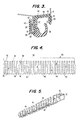
- FIG. 6 shows a sealing and guiding structure 70 having a first U-shaped portion 72, a second U-shaped portion 74 and a third U-shaped portion 76.
- the U-shaped portion 76 attaches to a vehicle flange 32.
- an outer wall 90 retains the window within the first U-shaped portion 72.
- a first central wall 92 forms the inner wall of the first U-shaped portion 72 and the outer wall of the second U-shaped portion 74.
- a second inner wall 94 completes the second U-shaped portion 74 and forms the outer wall of the third U-shaped portion 76.
- a sealing lip 96 is clamped between walls 92 and 94 and has its own carrier 98.
- a carrier 80 extends throughout the sealing and guiding element 70 and is formed from a single piece of metal.
- the carrier is bent back on itself at bend 82 to form the support structure for wall 92. Accordingly, in this area, there is a double thickness of carrier.
- this carrier has four parallel walls which must be bent in order to longitudinally bend the sealing and guiding element to conform to the window shape. Accordingly, this carrier is particularly rigid in the longitudinal direction. By punching all of the carrier except for the portion 100 in the outer wall 90, the carrier can be made more flexible and can easily be roll formed.
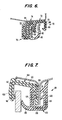
- Fig. 7 shows a third sealing and guiding element 101 which is composed of two separate members.
- a first member 104 is generally U-shaped and has an outer wall 106 and an inner wall 108 connected by a web portion 110.
- a first carrier 112 forms the support for member 104.
- Carrier 112 includes a solid portion 114 imbedded in the outer wall 104. The remainder of carrier 112 is punched so as to enable this portion of the carrier to be easily roll formed to conform to the shape of the window.
- a second member 120 is also U-shaped and has a first leg 122 and a second leg 124 interconnected by a web portion 126.
- a flocked sealing lip 130 extends toward wall 106.
- This member has its own carrier 132. This carrier can be completely punched if desired so as to enable member 120 to be flexed into the desired shape when it is applied to the vehicle.
- the member 104 is first applied to the vehicle flange 32 and is glued or riveted in place. Member 120 is then applied over the flange 32 and inner wall 108 to help hold member 104 to the vehicle body.
- each of the sealing and guiding elements forms a decorative trim piece on the interior of the vehicle.
- wall 122 of sealing and guiding element 101 is exposed to the interior of the vehicle and is intended to be aesthetic. Because a punched carrier is used in this wall, ordinarily, there would be read through of the punched carrier which would compromise the aesthetics of the element. However, it is conventional to flock the outer surface of this member. Flocking provides a rougher surface which hides read through. However, if it is desired to have a smooth surface on the interior, member 120 of sealing and guiding element 101 can also be made with a partially solid and partially punched carrier. That is, the portion of the carrier 132 within inner wall 122 could be made solid to eliminate read through.
- both element 104 and element 120 could be easily manufactured and roll formed into the desired shape and then mounted in place. There would be no read through on either the interior or the exterior of the sealing and guiding element so that aesthetic appeal would be maintained on both the inside and the outside of the vehicle without the need for any flocking applied to exterior surfaces.
Landscapes
- Engineering & Computer Science (AREA)
- Mechanical Engineering (AREA)
- Seal Device For Vehicle (AREA)
- Window Of Vehicle (AREA)
Abstract
Description
- This invention relates to sealing elements for automobiles and more particularly to sealing elements for flush mounted vehicle windows.
- In the design of modern automobiles, it is well-known that a low coefficient of drag of the vehicle body provides enhanced performance and reduced fuel consumption. Thus, one constraint of modern design engineers is the coefficient of drag figure. In order to reduce the drag coefficient, vehicle windows may be designed to be flush or substantially flush with the outer surface of the vehicle body. However, it is difficult to seal a flush mounted moveable window against the elements. It is therefore desireable to have some type of outer window guide member to prevent the window from moving away from the vehicle body leaving air gaps. However, at the same time, any such outer guide member must be relatively thin so that the window will still be substantially flush with the vehicle body. Furthermore, the outer guide member must be easily mounted to the vehicle.
- In order to provide flush mounted windows, it has been suggested to use a relatively rigid sealing member to both seal and guide a moveable window. For example, Published French Application No. 2,546,113 and Published French Application No. 2,564,047 show window seals having a very rigid carrier so that the seal itself is rigid. An outer wall of the seal actually provides an outer restraining wall for the moveable window. This type of structure has been found to be quite effective in use. However, the manufacture of such a seal can be difficult in that, because the seal is rigid, a roll forming apparatus must be used to conform the seal to the window opening. Because the carrier is rigid and has planar walls in two planes, bending the seal can be a difficult procedure.
- Seals having punched and corrugated carriers to promote longitudinal flexibility are also known. Such flexible seals avoid the problem of requiring a roll forming apparatus to shape the carrier, but may not have the necessary rigidity for use as a window retaining element. Also, because punched or corrugated carriers are not smooth, when a coating is extruded onto the carrier, "read through" occurs wherein the coating takes on the shape of the carrier. This produces a rough external appearance which is not appropriate for use on the external surface of a vehicle.
- One object of the present invention is to provide a sealing element for a flush mounted moveable vehicle window which will provide a positive seal against the window by inhibiting outward movement of the window, yet permit a substantially flush window configuration.
- Another object of the present invention is to provide a sealing element for flush mounted windows in which there is no read through so that a smooth, substantially planar and aesthetic appearance is presented.
- A further object of the present invention is to provide a sealing element for flush mounted windows which can be relatively easily shaped by a conventional roll forming apparatus into the shape of a window opening.
- In accordance with the above and other objects, the present invention comprises a first member for making contact and being retained in an opening for receiving a moveable window and a second member cooperating with the first member for defining a window channel. The second member forms an outer restraint for the window. A common carrier extends between and forms a support for the first member and the second member. The common carrier comprises a rigid metal and has an imperforate, substantially planar, shape-sustaining, longitudinally rigid portion in the second member and a longitudinally flexible portion in the first member.
- The longitudinally flexible portion of the carrier may have perforations or corrugations to provide longitudinal flexibility.
- The first and second members form a first generally U-shaped element having an outer leg and an inner leg. The invention may also include a second generally U-shaped element wherein the outer leg of the first U-shaped element is substantially planar and forms the outer window restraint, and the carrier extends through the U-shaped elements and is longitudinally rigid in the outer leg and longitudinally flexible otherwise. The second U-shaped element may have a common wall with the first U-shaped element.
- The present invention also contemplates a method comprising forming a window seal carrier by modifying an elongated strip of relatively rigid metal so that a first elongated portion of the metal remains relatively rigid and a second elongated portion of the metal is relatively flexible. The carrier is transversely bent to form a window guide channel such that the first elongated portion forms an outer guiding and retaining wall for a window received in the channel. The carrier is longitudinally bent to take the shape of a window opening.
- The second elongated portion of the metal may be made relatively flexible by forming perforations therein or by forming corrugations therein.
- The method may further comprise applying a coating of soft material over the carrier. The coating may be applied by extrusion.
- The above and other objects will become more readily apparent as the invention is more fully understood from the detailed description to follow, reference being had to the accompanying drawings in which like reference numerals represent like parts throughout, and in which:
- Fig. 1 is a side elevational view of an automobile door incorporating a seal according to the present invention;
- Fig. 2 is a perspective view showing the relationship of a seal according to the present invention and a moveable window;
- Fig. 3 is a transverse sectional view of a first embodiment of the seal of the present invention;
- Fig. 4 is a top plan view of the punched carrier of the seal in Fig. 3;
- Fig. 5 is a perspective view of the punched carrier transversely bent to form the profile of the seal of Fig. 3;
- Fig. 6 is a transverse sectional view of a second embodiment of the seal of the present invention; and
- Fig. 7 is a transverse sectional view of a third embodiment of the seal according to the present invention.
- Fig. 1 shows a
typical automobile door 10 having a verticallymoveable window 12 mounted in a sealing and guidingstructure 14 according to the present invention.Structure 14 extends around the top of thewindow 12 and is bent at corners 12a, 12b and 12c to conform to the shape of the window opening. - Fig. 2 shows the configuration of the sealing and guiding
structure 14. This structure has a first U-shapedportion 18 comprising anouter wall 20, asecond wall 22 and aweb portion 24 extending betweenwalls second U-shaped portion 26 formed of aninner wall 28,wall 22 and asecond web portion 30. The second U-shapedportion 26 attaches to abody flange 32 of the automobile, as shown in Fig. 3. The length of theweb portion 24 is sufficient that theouter wall 20 is substantially flush with the outer surface of the vehicle door panel 34. - A
sealing lip 36 is mounted on the U-shapedportion 26 and extends toward thewall 20 so as to form a seal againstwindow 12. Flocking 21 may be applied to the inner surface of U-shapedmember 18 and the outer surface of thesealing lip 36 as shown in Figs. 2 and 3 to reduce friction and promote sliding of thewindow 12. - The sealing and guiding
structure 14 is formed with acarrier member 40 over which a layer of rubber orsynthetic resin 41 is extruded. In prior designs, thecarrier member 40 has been solid and inflexible longitudinally. This made it difficult to bend the structure to conform to the shape of the window opening. - According to the present invention, as shown in Fig. 3, the
carrier 40 extends through the entire width of the sealing and guidingstructure 14 but is solid only inside ofwall 20. The carrier is punched as shown atopenings 42 elsewhere. In this manner, only theouter wall 40 of the carrier is solid and rigid. The remainder of the carrier is relatively flexible so that the sealing and guidingstructure 14 can be more easily bent to conform to the window shape using a roll bending apparatus. - Fig. 4 shows the punched
carrier 40 in greater detail. The carrier may be made from steel, aluminum or other rigid material. Preferably, the carrier is made from one millimeter thick steel so that it is substantially rigid and resists bending. The carrier is punched using known techniques so as to leave a longitudinal portion of thecarrier 50 imperforate and substantially planar but so as to formopenings 42 in the remainder of the carrier. The size and the positioning of theopenings 42 are consistent with standard punched carriers as would be apparent to one of ordinary skill in the art. As is conventional with punched carriers, the openings ultimately form strips ofmaterial 44 which are parallel and interconnected bywebs 46. However, unlike conventional punched carriers, theportion 50 along one lateral edge of the carrier remains solid. - After the carrier is punched, it is transversely bent into the shape of the sealing and guiding
element 14, as shown in Fig. 5. As can be clearly seen in Fig. 5, the rigid, substantiallyplanar portion 50 forms a support for theouter wall 20, whereas the punched portion of the carrier forms the support forwalls webs perforations 42, the punched portion of the carrier can be made as flexible as desired. For example, the perforations can be approximately an eighth of an inch thick leavingmetal strips 44 which are about 3/16 inch thick. Theweb portions 46 then have a length equal to about the thickness of theopenings 42 and can have a width approximately the same size. As a consequence, when thecarrier 40 is longitudinally bent, roll forming is required in only a single plane since the remainder of the carrier is highly flexible. This facilitates the roll forming operation, reduces cost and results in a much neater and cleaner bend. - After the
carrier 40 is transversely bent as shown in Fig. 5, the coating ofrubber 41 or the like is extruded over the carrier. Sealing lips may be formed wherever desired, such as on theouter wall 20, during this extrusion process. Additional sealing lips such as sealinglip 36 can either be formed of thesame rubber coating 41 or can be formed in a co-extrusion process using a softer material. - The final coated product is longitudinally bent into the shape of the window opening. It is noted that the
solid portion 50 of the carrier gives the final product a rigidity which is useful for automated assembly of the sealing and guidingstrip 14 in the door. That is, it is preferable to have the sealing and guidingstrip 14 rigid in its final shape so that it can be fit directly into the door opening. Also, theouter wall 20 is relatively rigid along its length to insure proper guiding of the window. Finally, the outer surface ofportion 50 of the carrier is substantially planar so that when the rubber coating 52 is extruded onto it, the outer surface of the rubber coating onwall 20 is also smooth and planar and presents an aesthetic, finished appearance which complements the finished appearance of the outside of the vehicle. - The length of the
wall 20 depends on the application. However, in practice, it has been found that a length of approximately 1/2 inch is adequate with the solid portion of the carrier being approximately 3/8 inch. This provides the desired degree of rigidity and enables the outer surface of the sealing and guidingelement 14 to be smooth and wrinkle-free. - It should be understood that any process which can produce a flexible portion of a carrier will suffice in place of a punching process. That is, while
web portions 46 are shown in Figs. 4 and 5 with adjacent web portions being offset from one another to provide flexibility, a portion of the carrier may be corrugated to provide flexibility. Any other process which will enable the same portion of the carrier to be flexible would also suffice. The primary concern is that the final product need be roll formed in only one plane so as to reduce the difficulty of this step in the manufacturing process. - A partially flexible and partially solid carrier according to the present invention can be used successfully in many different sealing and guiding structures. For example, Fig. 6 shows a sealing and guiding
structure 70 having a firstU-shaped portion 72, a secondU-shaped portion 74 and a thirdU-shaped portion 76. TheU-shaped portion 76 attaches to avehicle flange 32. In this structure, anouter wall 90 retains the window within the firstU-shaped portion 72. A firstcentral wall 92 forms the inner wall of the firstU-shaped portion 72 and the outer wall of the secondU-shaped portion 74. A secondinner wall 94 completes the secondU-shaped portion 74 and forms the outer wall of the thirdU-shaped portion 76. A sealinglip 96 is clamped betweenwalls own carrier 98. In this configuration, acarrier 80 extends throughout the sealing and guidingelement 70 and is formed from a single piece of metal. The carrier is bent back on itself atbend 82 to form the support structure forwall 92. Accordingly, in this area, there is a double thickness of carrier. In addition, this carrier has four parallel walls which must be bent in order to longitudinally bend the sealing and guiding element to conform to the window shape. Accordingly, this carrier is particularly rigid in the longitudinal direction. By punching all of the carrier except for theportion 100 in theouter wall 90, the carrier can be made more flexible and can easily be roll formed. - Fig. 7 shows a third sealing and guiding
element 101 which is composed of two separate members. Afirst member 104 is generally U-shaped and has anouter wall 106 and aninner wall 108 connected by aweb portion 110. Afirst carrier 112 forms the support formember 104.Carrier 112 includes asolid portion 114 imbedded in theouter wall 104. The remainder ofcarrier 112 is punched so as to enable this portion of the carrier to be easily roll formed to conform to the shape of the window. - A
second member 120 is also U-shaped and has afirst leg 122 and asecond leg 124 interconnected by aweb portion 126. A flocked sealinglip 130 extends towardwall 106. This member has itsown carrier 132. This carrier can be completely punched if desired so as to enablemember 120 to be flexed into the desired shape when it is applied to the vehicle. - The
member 104 is first applied to thevehicle flange 32 and is glued or riveted in place.Member 120 is then applied over theflange 32 andinner wall 108 to help holdmember 104 to the vehicle body. - It should also be noted that the inner wall of each of the sealing and guiding elements forms a decorative trim piece on the interior of the vehicle. For example,
wall 122 of sealing and guidingelement 101 is exposed to the interior of the vehicle and is intended to be aesthetic. Because a punched carrier is used in this wall, ordinarily, there would be read through of the punched carrier which would compromise the aesthetics of the element. However, it is conventional to flock the outer surface of this member. Flocking provides a rougher surface which hides read through. However, if it is desired to have a smooth surface on the interior,member 120 of sealing and guidingelement 101 can also be made with a partially solid and partially punched carrier. That is, the portion of thecarrier 132 withininner wall 122 could be made solid to eliminate read through. In this manner, bothelement 104 andelement 120 could be easily manufactured and roll formed into the desired shape and then mounted in place. There would be no read through on either the interior or the exterior of the sealing and guiding element so that aesthetic appeal would be maintained on both the inside and the outside of the vehicle without the need for any flocking applied to exterior surfaces. - The foregoing description is set forth for the purpose of illustrating the present invention but is not intended to limit the invention. Clearly, numerous substitutions, additions and other changes could be made to the invention without departing from the scope thereof as set forth in the appended claims.
Claims (20)
a first member for making contact with and being retained in an opening for receiving a movable window;
a second member cooperating with said first member for defining a window channel, said second member forming an outer restraint for said window;
a common carrier extending between and forming a support for said first member and said second member, said common carrier comprising a rigid metal and having an imperforate, substantially planar, shape-sustaining, longitudinally rigid portion in said second member and having a longitudinally flexible portion in said first member.
an elongated member having a portion which is longitudinally relatively flexible and a portion which is longitudinally relatively rigid, said longitudinally relatively rigid portion forming an outer window restraint, and said longitudinally relatively flexible portion defining with said longitudinally relatively rigid portion a window channel; and
a sealing lip formed on at least one of said longitudinally relatively flexible portion and said longitudinally relatively rigid portion for sealing against a window received in said window channel.
forming a window seal carrier by modifying an elongated strip of relatively rigid metal so that a first elongated portion of said metal remains relatively rigid and is relatively planar, and a second elongated portion of said metal is relatively flexible;
transversely bending said carrier to form a window guide channel such that said first elongated portion of said metal forms an outer guiding and retaining wall for a window received in said channel; and
longitudinally bending said carrier to take the shape of a window opening.
Applications Claiming Priority (2)
| Application Number | Priority Date | Filing Date | Title |
|---|---|---|---|
| US9442787A | 1987-09-09 | 1987-09-09 | |
| US94427 | 1987-09-09 |
Publications (2)
| Publication Number | Publication Date |
|---|---|
| EP0307304A2 true EP0307304A2 (en) | 1989-03-15 |
| EP0307304A3 EP0307304A3 (en) | 1990-03-21 |
Family
ID=22245129
Family Applications (1)
| Application Number | Title | Priority Date | Filing Date |
|---|---|---|---|
| EP88402243A Withdrawn EP0307304A3 (en) | 1987-09-09 | 1988-09-07 | Sealing element for flush mounted window |
Country Status (2)
| Country | Link |
|---|---|
| EP (1) | EP0307304A3 (en) |
| JP (1) | JPH023525A (en) |
Cited By (6)
| Publication number | Priority date | Publication date | Assignee | Title |
|---|---|---|---|---|
| FR2648887A1 (en) * | 1989-06-21 | 1990-12-28 | Draftex Ind Ltd | METAL REINFORCING SEAL TAPE |
| EP0412782A3 (en) * | 1989-08-07 | 1991-04-17 | The Standard Products Company | Integral trim and glass run channel |
| EP0748711A1 (en) * | 1995-06-12 | 1996-12-18 | Draftex Industries Limited | Reinforcements for sealing, trimming and finishing strips and methods of making such reinforcements |
| FR2775224A1 (en) * | 1998-02-26 | 1999-08-27 | Btr Sealing Systems France | NOVEL SEALING PROFILE FOR SLIDING WINDOW FRAME, ESPECIALLY A MOTOR VEHICLE DOOR, AND MANUFACTURING METHOD THEREOF |
| FR2794692A1 (en) * | 1999-06-14 | 2000-12-15 | Btr Sealing Systems France | NEW RIGID FRAME FOR ELASTOMER OR PLASTOMER PROFILE AND PROFILE EQUIPPED WITH THIS FRAME |
| WO2008006409A1 (en) * | 2006-07-12 | 2008-01-17 | Meteor Gummiwerke K.H. Bädje GmbH & Co. KG | Sealing arrangement |
Family Cites Families (6)
| Publication number | Priority date | Publication date | Assignee | Title |
|---|---|---|---|---|
| GB640966A (en) * | 1948-02-03 | 1950-08-02 | Beckett Laycock & Watkinson | Improvements in or relating to windows |
| US3108338A (en) * | 1961-01-06 | 1963-10-29 | Republic Ind Corp | Weather sealing strips and mounting means therefor |
| DE2558817A1 (en) * | 1975-01-09 | 1976-07-15 | Draftex Dev Ag | SEALING TAPE |
| DE8204475U1 (en) * | 1982-02-18 | 1985-11-28 | Schlegel Gmbh, 2000 Hamburg | Sealing strip made of polymer material with a metallic insert |
| GB2140065B (en) * | 1983-05-19 | 1986-09-24 | Mesnel Sa Ets | A sealing strip for a retractible window |
| EP0241264B1 (en) * | 1986-04-07 | 1990-08-22 | Bridgestone Australia Ltd., | Glass run channel |
-
1988
- 1988-09-07 EP EP88402243A patent/EP0307304A3/en not_active Withdrawn
- 1988-09-09 JP JP63226306A patent/JPH023525A/en active Pending
Cited By (10)
| Publication number | Priority date | Publication date | Assignee | Title |
|---|---|---|---|---|
| FR2648887A1 (en) * | 1989-06-21 | 1990-12-28 | Draftex Ind Ltd | METAL REINFORCING SEAL TAPE |
| EP0412782A3 (en) * | 1989-08-07 | 1991-04-17 | The Standard Products Company | Integral trim and glass run channel |
| US5095656A (en) * | 1989-08-07 | 1992-03-17 | The Standard Products Company | Integral trim and glass run channel |
| AU646636B2 (en) * | 1989-08-07 | 1994-03-03 | Standard Products Company, The | Integral trim and glass run channel |
| EP0748711A1 (en) * | 1995-06-12 | 1996-12-18 | Draftex Industries Limited | Reinforcements for sealing, trimming and finishing strips and methods of making such reinforcements |
| FR2775224A1 (en) * | 1998-02-26 | 1999-08-27 | Btr Sealing Systems France | NOVEL SEALING PROFILE FOR SLIDING WINDOW FRAME, ESPECIALLY A MOTOR VEHICLE DOOR, AND MANUFACTURING METHOD THEREOF |
| EP0938995A1 (en) | 1998-02-26 | 1999-09-01 | Btr Sealing Systems France | Sealing profile for sliding window, especially for a motor vehicle door and method for making same |
| FR2794692A1 (en) * | 1999-06-14 | 2000-12-15 | Btr Sealing Systems France | NEW RIGID FRAME FOR ELASTOMER OR PLASTOMER PROFILE AND PROFILE EQUIPPED WITH THIS FRAME |
| EP1060929A1 (en) * | 1999-06-14 | 2000-12-20 | Btr Sealing Systems France | Rigid reinforcement for elastomer or plastomer profile and profile with that reinforcement |
| WO2008006409A1 (en) * | 2006-07-12 | 2008-01-17 | Meteor Gummiwerke K.H. Bädje GmbH & Co. KG | Sealing arrangement |
Also Published As
| Publication number | Publication date |
|---|---|
| JPH023525A (en) | 1990-01-09 |
| EP0307304A3 (en) | 1990-03-21 |
Similar Documents
| Publication | Publication Date | Title |
|---|---|---|
| CA2147067C (en) | Weatherstrip assembly including a glass run channel and belt weatherstrip with decorative cover | |
| US4949507A (en) | One-piece expandable weatherstrip | |
| US5194312A (en) | Profiled sealing strip with two reinforcing bands | |
| US5095656A (en) | Integral trim and glass run channel | |
| CA2028774C (en) | One-piece weatherstrip with constant cross-section at corner bends | |
| US4800681A (en) | Sealing and guiding element for flush mounted movable automobile window | |
| EP0532163B1 (en) | Weatherstrip of expandable width | |
| EP0327141A2 (en) | Structure for windows in an automobile | |
| US5475947A (en) | Flexible sealing unit for movable windows | |
| JPH078636B2 (en) | Seal strip | |
| JPS59223517A (en) | Method and device for mounting window glass to window opening | |
| JP2001341591A (en) | Door seal structure | |
| EP0307304A2 (en) | Sealing element for flush mounted window | |
| KR970005782B1 (en) | Vehicle Mounting Molding | |
| JPH05139217A (en) | Weatherstrip for automobile | |
| EP0246008A1 (en) | Weatherstrip | |
| JP3040334B2 (en) | Weather strip with core | |
| GB2421268A (en) | Sealing, trimming and finishing strips and vehicle doors incorporating such strips | |
| GB2429027A (en) | Window sealing and guiding arrangements | |
| JP2677109B2 (en) | Automotive weather strip | |
| JP3178325B2 (en) | Door glass weather strip mounting structure | |
| JPH1148879A (en) | Opening trim for automobile | |
| JPH0542889Y2 (en) | ||
| JPH04238728A (en) | Weather strip for automobile | |
| KR800001320B1 (en) | Improvements in and relating to channel shaped sealing finishing and guide strips |
Legal Events
| Date | Code | Title | Description |
|---|---|---|---|
| PUAI | Public reference made under article 153(3) epc to a published international application that has entered the european phase |
Free format text: ORIGINAL CODE: 0009012 |
|
| AK | Designated contracting states |
Kind code of ref document: A2 Designated state(s): DE FR GB |
|
| PUAL | Search report despatched |
Free format text: ORIGINAL CODE: 0009013 |
|
| AK | Designated contracting states |
Kind code of ref document: A3 Designated state(s): DE FR GB |
|
| RAP1 | Party data changed (applicant data changed or rights of an application transferred) |
Owner name: SHELLER-GLOBE CORPORATION |
|
| 17P | Request for examination filed |
Effective date: 19900706 |
|
| 17Q | First examination report despatched |
Effective date: 19910604 |
|
| STAA | Information on the status of an ep patent application or granted ep patent |
Free format text: STATUS: THE APPLICATION IS DEEMED TO BE WITHDRAWN |
|
| 18D | Application deemed to be withdrawn |
Effective date: 19911015 |