EP0306737A2 - Hydraulic pulling device - Google Patents
Hydraulic pulling device Download PDFInfo
- Publication number
- EP0306737A2 EP0306737A2 EP88113294A EP88113294A EP0306737A2 EP 0306737 A2 EP0306737 A2 EP 0306737A2 EP 88113294 A EP88113294 A EP 88113294A EP 88113294 A EP88113294 A EP 88113294A EP 0306737 A2 EP0306737 A2 EP 0306737A2
- Authority
- EP
- European Patent Office
- Prior art keywords
- pressure
- working cylinder
- cylinder
- working
- end wall
- Prior art date
- Legal status (The legal status is an assumption and is not a legal conclusion. Google has not performed a legal analysis and makes no representation as to the accuracy of the status listed.)
- Withdrawn
Links
Images
Classifications
-
- F—MECHANICAL ENGINEERING; LIGHTING; HEATING; WEAPONS; BLASTING
- F15—FLUID-PRESSURE ACTUATORS; HYDRAULICS OR PNEUMATICS IN GENERAL
- F15B—SYSTEMS ACTING BY MEANS OF FLUIDS IN GENERAL; FLUID-PRESSURE ACTUATORS, e.g. SERVOMOTORS; DETAILS OF FLUID-PRESSURE SYSTEMS, NOT OTHERWISE PROVIDED FOR
- F15B7/00—Systems in which the movement produced is definitely related to the output of a volumetric pump; Telemotors
-
- B—PERFORMING OPERATIONS; TRANSPORTING
- B25—HAND TOOLS; PORTABLE POWER-DRIVEN TOOLS; MANIPULATORS
- B25B—TOOLS OR BENCH DEVICES NOT OTHERWISE PROVIDED FOR, FOR FASTENING, CONNECTING, DISENGAGING OR HOLDING
- B25B27/00—Hand tools, specially adapted for fitting together or separating parts or objects whether or not involving some deformation, not otherwise provided for
- B25B27/02—Hand tools, specially adapted for fitting together or separating parts or objects whether or not involving some deformation, not otherwise provided for for connecting objects by press fit or detaching same
- B25B27/026—Hand tools, specially adapted for fitting together or separating parts or objects whether or not involving some deformation, not otherwise provided for for connecting objects by press fit or detaching same fluid driven
-
- B—PERFORMING OPERATIONS; TRANSPORTING
- B25—HAND TOOLS; PORTABLE POWER-DRIVEN TOOLS; MANIPULATORS
- B25B—TOOLS OR BENCH DEVICES NOT OTHERWISE PROVIDED FOR, FOR FASTENING, CONNECTING, DISENGAGING OR HOLDING
- B25B27/00—Hand tools, specially adapted for fitting together or separating parts or objects whether or not involving some deformation, not otherwise provided for
- B25B27/02—Hand tools, specially adapted for fitting together or separating parts or objects whether or not involving some deformation, not otherwise provided for for connecting objects by press fit or detaching same
- B25B27/06—Hand tools, specially adapted for fitting together or separating parts or objects whether or not involving some deformation, not otherwise provided for for connecting objects by press fit or detaching same inserting or withdrawing sleeves or bearing races
- B25B27/064—Hand tools, specially adapted for fitting together or separating parts or objects whether or not involving some deformation, not otherwise provided for for connecting objects by press fit or detaching same inserting or withdrawing sleeves or bearing races fluid driven
Definitions
- the invention relates to a hydraulic pulling device for removing and pressing in bearings or sleeves, in particular for axle bearings (roller bearings) of motor vehicles, consisting of a working cylinder with a working piston and a piston rod projecting through the end wall of the working cylinder, and of a smaller-diameter pressure cylinder, which with is connected to the working cylinder and in which a pressure piston actuated by a threaded spindle is arranged, which presses a hydraulic pressure medium into the larger diameter cylinder during its pressure movement.
- the working cylinder and the pressure cylinder are in a coaxial arrangement in the form of cylindrical axial bores of different diameters in a common cylindrical body housed, which is provided at one end with an external thread and at the other end with a key profile.
- the working chamber of the working cylinder in which the working piston is located has a diameter that is about 2.5 times larger than the pressure chamber of the pressure cylinder and is openly worked into the cylindrical body from the end face provided with the external thread.
- a guide tube provided over its entire length with an external thread can be fastened in the end, in which a pressure tappet, which is detachably connected to the working piston by a threaded pin, is guided.
- a threaded spindle is screwed into the cylindrical body from the opposite end, which acts on a pressure piston which is axially movably guided in order to convey a pressure medium from the pressure cylinder into the larger diameter working cylinder.
- This known device is used in such a way that on the guide tube provided with an external thread, in which the pressure tappet is guided, a support device consisting of a cross bar and gripper fingers with barbs is screwed on and hung, for example, on a gearwheel or a pulley to be removed from a shaft journal , so that the lower end of the pressure plunger sits on the end face of the shaft to be pressed out of the gear.
- a support device consisting of a cross bar and gripper fingers with barbs is screwed on and hung, for example, on a gearwheel or a pulley to be removed from a shaft journal , so that the lower end of the pressure plunger sits on the end face of the shaft to be pressed out of the gear.
- Hydraulic systems are also already known in which the clamping force introduced manually by means of a screw can be redirected or distributed simultaneously or differently to different clamping parts by means of plastic mass or oil.
- the preferred area of application for such hydraulic systems is multi-piece clamping by hand. Instead of mechanical clamping force transmission, the greater the number of workpieces to be clamped, the more possible.
- only small clamping strokes are provided in these known systems. For larger clamping strokes they are not suitable because there is only one rotary screw with a relatively small pressure stroke.
- the invention has for its object to provide a hydraulic pulling device of the type mentioned in a construction that is characterized in particular by a small axial length and in which the achievable maximum working strokes of the working piston are at least approximately as large as the pressure stroke of a pressure piston.
- the embodiment of the invention according to claim 2 provides the advantageous possibility of achieving different power transmission ratios between the individual pressure cylinders and the working cylinder, which can have an effect on the amount of the maximum tractive force and also on the working speed.
- the embodiment of the invention according to claim 10 not only gives the possibility of limiting the working stroke of the working piston. With the threaded spindle which can be penetrated into the working cylinder, it is also possible to push the working piston and thus also the pressure piston back into their starting positions.
- the ventilation bore provided in accordance with claim 11 facilitates the axial movements of the working piston in a known manner.
- the same purpose also serves the embodiment of the invention according to claim 12, by which the possibility is created, for example, to move the working piston manually in the direction of the normal working stroke relative to the sealing sleeve, which remains in place during this movement while between the lateral surface of the Working piston and the inner surface of the working cylinder can flow air from one end face of the piston to the other end face due to the slight radial play there.
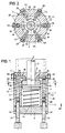
- a hydraulic pulling device which consists essentially of a one-piece cylinder body 1 with a fixed end wall 2 and an attached end wall 3.
- This cylinder body 1 contains a working cylinder 4 in the form of a cylindrical chamber concentric with the axis 5 of the cylinder body 1, which extends axially between the end walls 2 and 3 and in which there is a working piston 6, the piston rod 7 of which is through a central bore 8 of the end wall 2 protrudes outwards.
- the working piston 6 is sealed by an annular seal 9 on the inner surface of the working cylinder 4, and it is under the influence of a compression spring 10 which is supported on the inside of the end wall 3 and which presses it against the end wall 2.
- a total of six pressure cylinders 12, 13, 14, 15, 16 and 17 are arranged in the wall 11 that closes the working cylinder 4 in the form of axially parallel bores with different diameters, which pass through pressure medium channels 18, 19, 20, 21, 22 and 23 are each individually connected to the pressure chamber 24 located between the working piston 6 and the end wall 2.
- the individual pressure medium channels each consist of a radial bore 25 and two axial bores 26 and 27, the axial bores 26 each running coaxially with one of the pressure cylinders 12 to 17 and the axial bores 27 being arranged in the annular surface 28 surrounding the bore 8 of the end wall 2.
- the radial bores 25 are each sealed tightly to the outside by sealing screws 29.
- each pressure piston 30 are axially movable, which can be actuated individually by threaded spindles 31.
- These threaded spindles 31 are each arranged in threaded bores 32 arranged coaxially with the individual pressure cylinders 12 to 17 in the end wall 3 such that they each experience an axial displacement during rotation in one direction or the other.
- Their diameters are each kept smaller than the diameters of the pressure cylinders, so that they can plunge unhindered into them in order to move their pressure pistons 30.
- the end wall 3 is connected to the cylinder body 1 by means of screws (not shown), the chamber of the working cylinder in which the compression spring is located and the chambers of the pressure cylinders 12 to 17, into which the threaded spindles 31 are immersed, to be ventilated.
- the pressure chamber 24 of the working cylinder 4 and with it Connected spaces of the pressure cylinders 12 to 17 including the pressure medium channels 18 to 23 are each filled with a liquid or paste-like pressure medium 35, which can consist, for example, of hydraulic oil or a pasty fat. If one or more of the threaded spindles are rotated one after the other in the direction of arrow 36 into a pressure cylinder 12 to 17, the pressure medium 35 located in front of it is pressed by the correspondingly moving pressure piston 30 through the connecting channel or channels 18 to 23 into the pressure chamber 28 of the working cylinder 4 and thereby the working piston 6 moves with its piston rod 7 in the opposite direction.
- a liquid or paste-like pressure medium 35 which can consist, for example, of hydraulic oil or a pasty fat.
- the compression spring 10 ensures that the pressure piston 6 moves again in the direction of arrow 36 against the end wall 2 and returns to its starting position.
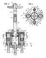
- the pressure cylinders 41 to 44 each sit sealingly in cylindrical recesses or blind bores 48, 49, 50, 51, which are arranged at the same radial spacing around a central threaded bore 52 at the same angular spacing, that is to say offset by 90 ° to one another, and through Pressure medium channels 53, 54, 55, 56 are each individually connected to the pressure chamber 57 of the working cylinder 40.
- the one end section of the tube forming the working cylinder 40 is provided with an external thread 58 which is screwed into the threaded bore 52 of the end wall plate 45 in a sealing manner.
- the forehead is in its center wall plate 45 has an axial bore 60 provided with sealing rings 59 and a concentric threaded shoulder 61.
- the piston rod 62 of a working piston 63 working cylinder 40 is guided.
- the piston rod 62 is provided at its outer end with a threaded pin 64 of smaller diameter, onto which an exchangeable pull rod 65 is screwed as an extension, and a threaded section 66 is provided at its free end with a screwed-on, plate-like pressure piece 67.
- the end wall plate 45 and the ring plate 46 which have a circular basic shape per se, are each provided with round radial incisions 68 between the individual pressure cylinders 41 to 44, which give them a cross-like shape.
- the end sections of the pressure cylinders 41 to 44 opposite the end wall plate 45 are each held in cylindrical end recesses 69 of the ring plate 46, which is guided in a centered manner by means of a central bore 70 on the tube forming the working cylinder 40 and is penetrated by it.
- the end section 71 of the working cylinder 40 protruding from the bore 70 of the ring plate 46 is also provided with an external thread 72, onto which an internal thread of the cylindrical end wall 47 is screwed. In this way, the end wall 47 with the tube forming the working cylinder 40 and the ring plate 46 with the pressure cylinders 41 to 44 connected.
- a ventilation hole 73 for the working cylinder 40.
- a threaded spindle 75 is screwed in, which can be used both as a stroke limit stop for the working piston 63 and also to push the working piston 33 back into its starting position from its position which it occupies at the end of a working stroke.
- the individual pressure cylinders 41 to 44 each have axially movable pressure pistons 76 which lie closely against the inner surfaces of the pressure cylinders and which can be individually actuated by threaded spindles 77. These threaded spindles 77 are each screwed in a coaxial arrangement to the individual pressure cylinders 41 to 44 in threaded bores 78 of the ring plate 46 and serve in the same way for actuating the pressure pistons 76 as the threaded spindle 31 for actuating the pressure pistons 30 in the embodiment of FIGS. 1 and 2 .
- a sealing sleeve 80 On the annular surface 79 of the working piston 63 which surrounds the piston rod 62, a sealing sleeve 80 is arranged, which seals both on the piston rod 62 and on the Inner surface of the pressure cylinder 40 abuts, but is otherwise not connected to the working piston 63.
- the sealing sleeve 80 With a manual movement of the working piston 63 in the direction of arrow 81 and stationary pressure piston 76, the sealing sleeve 80 thus has the possibility of remaining in its current position, so that no negative pressure arises in the pressure chamber 57, which leads to a displacement of the pressure piston 76 in the individual pressure cylinders 41 to 44 could lead.
- an O-ring 82 made of hard rubber, for example, is inserted between its outer and inner ring lips.
- the pressure medium 83 with which the cavities of the pressure cylinders 41 to 44, as well as the connecting channels 53 to 56 and the pressure chamber 57 of the working cylinder 40, are filled between the pressure pistons 76 and the end wall plate 45, consists of a pasty grease, such as is used for wheel bearings is used on motor vehicles.
- the method of operation is in principle the same as in the exemplary embodiment in FIGS. 1 and 2.
- the presence of the threaded shoulder 61 on the end wall plate 45 makes it possible to screw the gas control device, for example, into a support plate or the like.
Abstract
Description
Die Erfindung betrifft eine hydraulische Ziehvorrichtung zum Abziehen und Einpressen von Lagern oder Hülsen, insbesondere für Achslager (Wälzlager) von Kraftfahrzeugen, bestehend aus einem Arbeitszylinder mit einem Arbeitskolben und einer die Stirnwand des Arbeitszylinders durchragenden Kolbenstange, sowie aus einem im Durchmesser kleineren Druckzylinder, der mit dem Arbeitszylinder in Verbindung steht und in dem ein von einer Gewindespindel betätigter Druckkolben angeordnet ist, welcher bei seiner Druckbewegung ein hydraulisches Druckmittel in den im Durchmesser größeren Arbeitszylinder preßt.The invention relates to a hydraulic pulling device for removing and pressing in bearings or sleeves, in particular for axle bearings (roller bearings) of motor vehicles, consisting of a working cylinder with a working piston and a piston rod projecting through the end wall of the working cylinder, and of a smaller-diameter pressure cylinder, which with is connected to the working cylinder and in which a pressure piston actuated by a threaded spindle is arranged, which presses a hydraulic pressure medium into the larger diameter cylinder during its pressure movement.
Bei einer bekannten Vorrichtung der gattungsgemäßen Art (DE-PS 1 291 700) sind der Arbeitszylinder und der Druckzylinder in zueinander koaxialer Anordnung in Form zylindrischer Axialbohrungen unterschiedlichen Durchmessers in einem gemeinsamen zylindrischen Körper untergebracht, der an seinem einen Ende mit einem Außengewinde und am anderen Ende mit einem Schlüsselprofil versehen ist. Die Arbeitskammer des Arbeitszylinders in welcher sich der Arbeitskolben befindet, hat einen um etwa das 2,5-Fache größeren Durchmesser die Druckkammer des Druckzylinders und ist von der mit dem Außengewinde versehenen Stirnseite her offen in den zylindrischen Körper eingearbeitet. Mittels eines auf das Außengewinde aufschraubbaren Spannringes ist stirnseitig ein über seine ganze Länge mit einem Außengewinde versehenes Führungsrohr befestigbar, in dem ein durch einen Gewindezapfen mit dem Arbeitskolben lösbar verbundener Druckstößel geführt ist. Von der gegenüberliegenden Stirnseite her ist in den zylindrischen Körper eine Gewindespindel eingeschraubt, die auf einen em Druckzylinder axial beweglich geführten Druckkolben einwirkt, um ein Druckmedium aus dem Druckzylinder in den im Durchmesser größeren Arbeitszylinder zu befördern.In a known device of the generic type (DE-PS 1 291 700) the working cylinder and the pressure cylinder are in a coaxial arrangement in the form of cylindrical axial bores of different diameters in a common cylindrical body housed, which is provided at one end with an external thread and at the other end with a key profile. The working chamber of the working cylinder in which the working piston is located has a diameter that is about 2.5 times larger than the pressure chamber of the pressure cylinder and is openly worked into the cylindrical body from the end face provided with the external thread. By means of a clamping ring that can be screwed onto the external thread, a guide tube provided over its entire length with an external thread can be fastened in the end, in which a pressure tappet, which is detachably connected to the working piston by a threaded pin, is guided. A threaded spindle is screwed into the cylindrical body from the opposite end, which acts on a pressure piston which is axially movably guided in order to convey a pressure medium from the pressure cylinder into the larger diameter working cylinder.
Verwendet wird diese bekannte Vorrichtung in der Weise, daß auf das mit einem Außengewinde versehene Führungsrohr, in dem der Druckstößel geführt ist, eine aus einem Querholm und Greiferfingern mit Widerhaken bestehende Stützvorrichtung aufgeschraubt und z.B. an einem von einem Wellenzapfen abzuziehenden Zahnrad oder einer Riemenscheibe eingehängt wird, so daß das untere Ende des Druckstößels auf der Stirnseite der aus dem Zahnrad herauszupressenden Welle aufsitzt. Durch entsprechendes Drehen der Gewindespindel werden dann am Druckstößel die axialen Abziehkräfte erzeugt, die proportional sind zum Verhältnis des Querschnitts des Druckzylinders zum Querschnitt des Arbeitszylinders.This known device is used in such a way that on the guide tube provided with an external thread, in which the pressure tappet is guided, a support device consisting of a cross bar and gripper fingers with barbs is screwed on and hung, for example, on a gearwheel or a pulley to be removed from a shaft journal , so that the lower end of the pressure plunger sits on the end face of the shaft to be pressed out of the gear. By turning the threaded spindle accordingly, the pressure tappet is then pressed generates the axial pulling forces, which are proportional to the ratio of the cross section of the pressure cylinder to the cross section of the working cylinder.
Abgesehen davon, daß bei dieser bekannten Vorrichtung schon durch die koaxial hintereinander liegende Anordnung des Druckzylinders und des Arbeitszylinders sowie des sich daran anschließenden Führungsrohrs mit dem Druckstößel eine relativ große Baulänge sich zwangsläufig ergibt, die überall dort hinderlich ist, wo um das zu bearbeitende Werkstück herum nur relativ kleine Freiräume vorhanden sind, sind mit dieser bekannten Vorrichtung nur relativ kurze Arbeitshübe zu erzielen deren Größenordnung im günstigsten Fall bei etwa dem fünfzehnten Teil der Gesamtlänge der Vorrichtung liegt.Apart from the fact that with this known device the coaxial arrangement of the pressure cylinder and the working cylinder and the adjoining guide tube with the pressure tappet inevitably results in a relatively large overall length, which is a hindrance wherever around the workpiece to be machined only relatively small free spaces are available, with this known device only relatively short working strokes can be achieved, the magnitude of which, in the best case, is approximately fifteenth of the total length of the device.
Es sind auch bereits hydraulische Systeme bekannt, bei denen durch plastische Masse oder Öl die von Hand durch eine Schraube eingeleitete Spannkraft gleichmäßig oder ungleichmäßig gleichzeitig auf verschiedene Spannteile umgelenkt bzw. verteilt werden kann. (K. Schreyer: Werkstückspanner, Springer Verlag 1969, Seite 126, 127) Das bevorzugte Anwendungsgebiet solcher hydraulischer Systeme ist das Mehrstückspannen durch Handkraft. Sie kommen anstelle mechanischer Spannkraftübertragung um so mehr in betracht, je größer die Anzahl der zugleich zu spannenden Werkstücke ist. Bei diesen bekannten Systemen sind aber nur geringe Spannhübe vorgesehen. Für größere Spannhübe sind sie nicht geeignet, weil nur eine Drehschraube mit relativ kleinem Druckhub vorhanden ist.Hydraulic systems are also already known in which the clamping force introduced manually by means of a screw can be redirected or distributed simultaneously or differently to different clamping parts by means of plastic mass or oil. (K. Schreyer: Workpiece clamp, Springer Verlag 1969, pages 126, 127) The preferred area of application for such hydraulic systems is multi-piece clamping by hand. Instead of mechanical clamping force transmission, the greater the number of workpieces to be clamped, the more possible. However, only small clamping strokes are provided in these known systems. For larger clamping strokes they are not suitable because there is only one rotary screw with a relatively small pressure stroke.
Der Erfindung liegt die Aufgabe zugrunde, eine hydraulische Ziehvorrichtung der eingangs genannten Art in einer Bauweise zu schaffen, die sich insbesondere durch eine geringe axiale Baulänge auszeichnet und bei der die erzielbaren maximalen Arbeitshübe des Arbeitskolbens wenigstens etwa gleich groß sind wie der Druckhub eines Druckkolbens.The invention has for its object to provide a hydraulic pulling device of the type mentioned in a construction that is characterized in particular by a small axial length and in which the achievable maximum working strokes of the working piston are at least approximately as large as the pressure stroke of a pressure piston.
Gelöst wird diese Aufgabe erfindungsgemäß dadurch, daß neben dem Arbeitszylinder in Parallellage zu diesem wenigstens zwei Druckzylinder mit jeweils durch Gewindespindeln betätigbaren Druckkolben angeordnet sind, welche durch Druckmittelkanäle einer gemeinsamen Stirnwand mit dem Arbeitszylinder in Verbindung stehen, und deren Hubvolumina gemeinsam wengistens so groß sind wie das Hobvolumen des Arbeitszylinders. Dadurch, daß die Druckzylinder nicht wie bei der bekannten Vorrichtung in axialer Verlängerung des Arbeitszylinders sondern neben dem Arbeitszylinder angeordnet sind, besteht erstens die Möglichkeit, mehrere solche Druckzylinder vorzusehen und zweitens ergibt sich dadurch eine wesentliche kompaktere Bauweise, die im wesentlichen durch die axiale Länge des Arbeitszylinders bestimmt wird. Dazu kommt, daß durch das Vorsehen mehrerer Druckzylinder die Möglichkeit besteht, die axiale Länge des Arbeitszylinders und damit auch den Arbeitshub des Arbeits kolbens wesentlich zu vergrößern, weil in dem mehrfach vorhandenen Druckzylindern insgesamt ein wesentlich größeres Druckmittelvolumen zur Verfügung steht, das zur Beaufschlagung des Arbeitskolbens verwendet werden kann als dies bei der bekannten Vorrichtung möglich ist. Ein weiterer Vorteil besteht darin, daß durch die sich aus der Anordnung der Druckzylinder und des Arbeitszylinders ergebende Umlenkung des Druckmittels der Arbeitskolben entgegengesetzt zu den Druckkolben beaufschlagt wird, daß sich also der Arbeitskolben gegenläufig zu den Druckkolben bewegt, was bedeutet, daß der Arbeitskolben in Zugrichtung belastbar ist, wenn die den einzelnen Druckkolben zugeordneten Gewindespindeln auf der dem Austritt der Kolbenstange gegenüberliegenden Seite angeordnet sind.This object is achieved according to the invention in that, in addition to the working cylinder in parallel with this, at least two pressure cylinders are arranged, each with pressure pistons that can be actuated by threaded spindles, which are connected to the working cylinder by pressure medium channels of a common end wall, and whose stroke volumes are generally as large as that Lifting volume of the working cylinder. The fact that the pressure cylinders are not arranged as in the known device in the axial extension of the working cylinder but next to the working cylinder, firstly, there is the possibility of providing several such cylinders and secondly, this results in a significantly more compact design, which is essentially due to the axial length of the Working cylinder is determined. In addition, there is the possibility by providing several pressure cylinders, the axial length of the working cylinder and thus also the working stroke of the work piston increase significantly, because in the multiple pressure cylinders there is a much larger volume of pressure medium available that can be used to act on the working piston than is possible with the known device. Another advantage is that due to the deflection of the pressure medium resulting from the arrangement of the pressure cylinder and the working cylinder, the working piston is acted opposite to the pressure piston, so that the working piston moves in the opposite direction to the pressure piston, which means that the working piston moves in the pulling direction is resilient if the threaded spindles assigned to the individual pressure pistons are arranged on the side opposite the outlet of the piston rod.
Durch die Ausgestaltung der Erfindung nach Anspruch 2 ergibt sich die vorteilhafte Möglichkeit, unterschiedliche Kraftübersetzungen zwischen den einzelnen Druckzylindern und dem Arbeitszylinder zu erreichen, was sich auf die Höhe der maximalen Zugkraft und auch günstig auf die Arbeitsgeschwindigkeit auswirken kann.The embodiment of the invention according to
Während die Ausgestaltungen nach den Ansprüchen 3 und 4 die Anordnung des Arbeitszylinders und der Druckzylinder in sehr kompakter Bauweise ermöglichen ist die Ausführungsform nach den Ansprüchen 5 bis 9, obwohl sie aus mehr Einzelteilen besteht, fertigungstechnisch einfacher. Insbesondere sind dabei die Innenflächen der Zylinder bzw. der diese bildenden Rohre leichter und präziser bearbeitbar.While the configurations according to
Durch die Ausgestaltung der Erfindung nach Anspruch 10 ist nicht nur die Möglichkeit gegeben, den Arbeitshub des Arbeitskolbens zu begrenzen. Mit der in den Arbeitszylinder eindringbaren Gewindespindel ist es auch möglich, den Arbeitskolben und damit auch die Druckkolben in ihre Ausgangspositionen zurückzudrücken.
Durch die nach Anspruch 11 vorgesehene Belüftungsbohrung werden die Axialbewegungen des Arbeitskolbens in bekannter Weise erleichtert.
Dem gleichen Zweck dient auch die Ausgestaltung der Erfindung nach Anspruch 12, durch welche die Möglichkeit geschaffen ist, den Arbeitskolben z.B. manuell in Richtung des normalen Arbeitshubes relativ zu der Dichtungsmanschette zu bewegen, die während dieser Bewegung an ihrer Stelle stehen bleibt während zwischen der Mantelfläche des Arbeitskolbens und der Innenfläche des Arbeitszylinders in Folge des dort vorhandenen geringen radialen Spiels Luft von der einen Stirnseite des Kolbens auf die andere Stirnseite strömen kann.The embodiment of the invention according to
The ventilation bore provided in accordance with
The same purpose also serves the embodiment of the invention according to
Gegenüber der Verwendung von Öl oder einer sonstigen Flüssigkeit als Druckmittel, bei der die Gefahr des Auslaufens an relativ kleinen Leckstellen groß ist, wird diese Gefahr durch die Verwendung von pastösem Fett gemäß Anspruch 13 stark vermindert.Compared to the use of oil or another liquid as a pressure medium, in which the risk of leakage at relatively small leakage points is great, this risk is strong due to the use of pasty fat reduced.
Anhand der Zeichnung wird die Erfindung im folgenden an zwei Ausführungsbeispielen näher erläutert.Es zeigt:
- Fig. 1 eine hydraulische Ziehvorrichtung im Schnitt;
- Fig. 2 einen Schnitt II-II aus Fig. 1;
- Fig. 3 eine andere hydraulische Ziehvorrichtung im Schnitt;
- Fig. 4 einen Schnitt IV-IV aus Fig. 3.
- 1 shows a hydraulic pulling device in section.
- FIG. 2 shows a section II-II from FIG. 1;
- 3 shows another hydraulic pulling device in section;
- 4 shows a section IV-IV from FIG. 3.
In den Fig. 1 und 2 ist eine hydraulische Ziehvorrichtung dargestellt, die im wesentlichen aus einem einstückigen Zylinderkörper 1 mit einer festen Stirnwand 2 und einer aufgesetzten Stirnwand 3 besteht. Dieser Zylinderkörper 1 beinhaltet einen Arbeitszylinder 4 in Form einer zur Achse 5 des Zylinderkörpers 1 konzentrischen zylindrischen Kammer, die sich axial zwischen den Stirnwänden 2 und 3 erstreckt und in welcher sich ein Arbeitskolben 6 befindet, dessen Kolbenstange 7 durch eine zentrale Bohrung 8 der Stirnwand 2 nach außen ragt. Der Arbeitskolben 6 ist durch eine Ringdichtung 9 an der Innenfläche des Arbeitszylinders 4 abgedichtet, und er steht unter dem Einfluß einer sich auf der Innenseite der Stirnwand 3 abstützenden Druckfeder 10, welche ihn gegen die Stirnwand 2 drückt. In der den Arbeitszylinder 4 unschließenden Wand 11 sind insgesamt sechs Druckzylinder 12, 13, 14, 15, 16 und 17 in Form von achsparallelen Bohrungen mit unterschiedlichen Durchmessern angeordnet, welche durch Druckmittelkanäle 18, 19, 20, 21, 22 und 23 jeweils einzeln mit der sich zwischen dem Arbeitskolben 6 und der Stirnwand 2 befindenden Druckkammer 24 in Verbindung stehen. Die einzelnen Druckmittelkanäle bestehen jeweils aus einer Radialbohrung 25 und zwei Axialbohrungen 26 bzw. 27, wobei die Axialbohrungen 26 jeweils koaxial zu einem der Druckzylinder 12 bis 17 verlaufen und die Axialbohrungen 27 in der die Bohrung 8 der Stirnwand 2 umgebenden Ringfläche 28 angeordnet sind. Durch Dichtungsschrauben 29 sind die Radialbohrungen 25 jeweils dicht nach außen verschlossen. In den Druckzylindern 12 bis 17 sind jeweils Druckkolben 30 axial beweglich angeordnet, die einzeln durch Gewindespindeln 31 betätigbar sind. Diese Gewindespindeln 31 sind jeweils in koaxial zu den einzelnen Druckzylindern 12 bis 17 in der Stirnwand 3 angeordneten Gewindebohrungen 32 so angeordnet, daß sie bei der Drehung in der einen oder anderen Richtung jeweils eine Axialvershiebung erfahren. Ihre Durchmesser sind dabei jeweils kleiner gehalten als die Durchmesser der Druckzylinder, so daß sie ungehindert in diese eintauchen können, um ihre Druckkolben 30 zu bewegen.
Die Stirnwand 3 ist mittels nicht dargestellter Schrauben mit dem Zylinderkörper 1 verbunden, wobei die Kammer des Arbeitszylinders in welcher sich die Druckfeder befindet und die Kammern der Druckzylinder 12 bis 17, in welche die Gewindespindeln 31 eintauchen, belüftet sein sollen.1 and 2, a hydraulic pulling device is shown, which consists essentially of a one-
The
Die Druckkammer 24 des Arbeitszylinders 4 und die mit dieser verbundenen Räume der Druckzylinder 12 bis 17 einschließlich der Druckmittelkanäle 18 bis 23 sind jeweils gefüllt mit einem flüssigen oder pastenartigen Druckmittel 35, das z.B. aus Hydrauliköl oder einem pastösen Fett bestehen kann.
Wird eine oder mehrere der Gewindespindeln nacheinander in Richtung des Pfeiles 36 in einen Druckzylinder 12 bis 17 hineingedreht, so wird durch den entsprechend mitbewegten Druckkolben 30 das sich davor befindende Druckmittel 35 durch den oder die Verbindungskanäle 18 bis 23 in die Druckkammer 28 des Arbeitszylinders 4 gepreßt und dadurch der Arbeitskolben 6 mit seiner Kolbenstange 7 in entgegengesetzter Richtung bewegt. Durch die Querschnittsunterschiede zwischen den Druckzylindern 12 bis 17 einerseits und der Druckkammer 28 andererseits ergeben sich Kraftübersetzungen, die dazu führen, daß an der Kolbenstange 7 entsprechend den gegebenen Querschnittsverhältnissen Zugkräfte wirksam werden die wesentlich größer sind als die Druckkräfte an den Gewindespindeln 31.
Durch die unterschiedlichen Durchmesser der einzelnen Druckzylinder 12 bis 17 ergeben sich sowohl unterschiedliche Kraftübersetzungen als auch unterschieldliche Weguntersetzungen.The
If one or more of the threaded spindles are rotated one after the other in the direction of arrow 36 into a
The different diameters of the
Um einen sich zumindest annähernd über die ganze axiale Länge des Arbeitszylinders 4 erstreckenden Arbeitshub des Arbeitskolbens 6 zu erzielen, ist es erforderlich, daß die Summe aller Volumina der einzelnen Druckzylinder 12 bis 17 zumindest gleich oder größer ist wie bzw. als das Maximalvolumen der Druck kammer 24 des Arbeitszylinders 6.In order to achieve a working stroke of the working
Wenn die Gewindespindeln 31 wieder zurückgedreht werden, sorgt die Druckfeder 10 dafür, daß der Druckkolben 6 sich wieder in Richtung des Pfeiles 36 gegen die Stirnwand 2 bewegt und in seine Ausgangslage zurückkehrt.When the threaded
Bei der in den Fig. 3 und 4 dargestellten hydraulischen Ziehvorrichtung, die im Prinzip den gleichen Grundaufbau aufweist, wie die in den Fig. 1 und 2 dargestellte Ziehvorrichtung, bestehen sowohl der Arbeitszylinder 40 als auch die nur in vierfacher Ausfertigung vorhandenen Druckzylinder 41, 42, 43 und 44 jeweils aus separaten zylindrischen Rohren unterschiedlichen Durchmessers, die durch eine gemeinsame Stirnwandplatte 45 und eine Ringplatte 46 sowie eine Stirnwand 47 zu einem Ganzen zusammengehalten sind. Dabei sitzen die Druckzylinder 41 bis 44 jeweils dichtend in zylindrischen Ausnehnumgen oder Sackbohrungen 48, 49, 50, 51, die in gleichen radialen Abständen um eine zentrale Gewindebohrung 52 herum in gleichen Winkelabständen, also jeweils um 90° zueinander versetzt, angeordnet sind und die durch Druckmittelkanäle 53, 54, 55, 56 jeweils einzeln mit der Druckkammer 57 des Arbeitszylinders 40 in Verbindung stehen. Dabei ist der eine Endabschnitt des den Arbeitszylinder 40 bildenden Rohres mit einem in die Gewindebohrung 52 der Stirnwandplatte 45 dichtend eingeschraubten Außengewinde 58 versehen. In ihrem Zentrum besitzt die Stirn wandplatte 45 eine mit Dichtungsringen 59 versehene Axialbohrung 60 und einen konzentrischen Gewindeansatz 61. In der Bohrung 60 ist die Kolbenstange 62 eines Arbeitskolbens 63 Arbeitszylinders 40 geführt. Die Kolbenstange 62 ist an ihrem äußeren Ende mit einem Gewindezapfen 64 kleineren Durchmessers versehen, auf den als Verlängerung eine auswechselbare Zugstange 65 aufgeschraubt ist, die an ihrem freien Ende einen Gewindeabschnitt 66 mit einem aufgeschraubten, tellerartigen Druckstück 67 versehen ist.
Aus Gewichtersparnisgründen sind die Stirnwandplatte 45 und die Ringplatte 46, die eine an sich kreisförmige Grundform aufweisen, zwischen den einzelnen Druckzylindern 41 bis 44 jeweils mit runden radialen Einschnitten 68 versehen, welche ihnen eine kreuzartige Form verleihen.In the hydraulic pulling device shown in FIGS. 3 and 4, which in principle has the same basic structure as the pulling device shown in FIGS. 1 and 2, there are both the working
For reasons of weight saving, the
Die der Stirnwandplatte 45 gegenüberliegenden Endabschnitte der Druckzylinder 41 bis 44 sind jeweils in zylindrischen stirnseitigen Ausnehmungen 69 der Ringplatte 46 gehalten, die mittels einer zentralen Bohrung 70 an dem den Arbeitszylinder 40 bildenden Rohr zentriert geführt ist und von diesem durchragt wird. Auch der aus der Bohrung 70 der Ringplatte 46 herausragende Endabschnitt 71 des Arbeitszylinders 40 ist mit einem Außengewinde 72 versehen, auf welches ein Innengewinde der zylindrischen Stirnwand 47 aufgeschraubt ist. Auf diese Weise ist die Stirnwand 47 mit dem den Arbeitszylinder 40 bildenden Rohr und die Ringplatte 46 mit den Druckzylindern 41 bis 44 verbunden. In der Stirnwand 47 befindet sich eine Belüftungsbohrung 73 für den Arbeitszylinder 40. Wenn die die Druckzylinder 41 bis 44 bildenden Rohre nicht luftdicht in die Ausnehmungen 69 eingesetzt sind, bedarf es dort keiner Belüftungsbohrungen in der Ringplatte 46.
In einer zentralen Gewindebohrung 74 der Stirnwand 47 ist eine Gewindespindel 75 eingeschraubt, die sowohl als Hubbegrenzungsanschlag für den Arbeitskolben 63 wie auch dazu benutzt werden kann, den Arbeitskolben 33 aus seiner Position, die er am Ende eines Arbeitshubes einnimmt, wieder in seine Ausgangslage zurückzudrücken.The end sections of the
In a central threaded
In den einzelnen Druckzylindern 41 bis 44 sind jeweils axial bewegliche und dicht an den Innenflächen der Druckzylinder anliegende Druckkolben 76 angeordnet, die durch Gewindespindeln 77 individuell betätigt werden können. Diese Gewindespindeln 77 sind jeweils in koaxialer Anordnung zu den einzelnen Druckzylindern 41 bis 44 in Gewindebohrungen 78 der Ringplatte 46 eingeschraubt und dienen in gleicher Weise zur Betätigung der Druckkolben 76, wie die Gewindespindel 31 zur Betätigung der Druckkolben 30 beim Ausführungsbeispiel der Fig. 1 und 2.The
Auf der die Kolbenstange 62 umschließenden Ringfläche 79 des Arbeitskolbens 63 ist eine Dichtungsmanschette 80 angeordnet, die sowohl dichtend an der Kolbenstange 62 als auch an der Innenfläche des Druckzylinders 40 anliegt, die aber im übrigen mit dem Arbeitskolben 63 nicht verbunden ist.
Bei einer manuellen Bewegung des Arbeitskolbens 63 in Richtung des Pfeiles 81 und stillstehenden Druckkolben 76 hat somit die Dichtungsmanschette 80 die Möglichkeit, in ihrer momentanen Position zu verbleiben, so daß in der Druckkammer 57 kein Unterdruck entsteht, der zu einer Verschiebung der Druckkolben 76 in den einzelnen Druckzylindern 41 bis 44 führen könnte. Um zu vermeiden, daß die Dichtungsmanschette an der inneren Stirnfläche der Stirnwandplatte 45 zur Anlage kommt und dort möglicherweise beschädigt wird, ist zwischen ihren äußeren und inneren Ringlippen ein z.B. aus Hartgummi bestehender O-Ring 82 eingelegt.On the
With a manual movement of the working
Das Druckmittel 83, mit dem die zwischen den Druckkolben 76 und der Stirnwandplatte 45 liegenden Hohlräume der Druckzylinder 41 bis 44 sowie die Verbindungskanäle 53 bis 56 und die Druckkammer 57 des Arbeitszylinders 40 gefüllt ist, besteht er aus einem pastösen Schmierfett, wie es beispielsweise für Radlager an Kraftfahrzeugen verwendet wird.The
Die Funktionsweise ist im Prinzip die gleiche wie beim Ausführungsbeispiel der Fig. 1 und 2. Durch das Vorhandensein des Gewindeansatzes 61 an der Stirnwandplatte 45 ist die Möglichkeit gegeben, die Gasamtvorrichtung beispielsweise in eine Stützplatte od. dgl. einer Abziehvorrichtung einzuschrauben.The method of operation is in principle the same as in the exemplary embodiment in FIGS. 1 and 2. The presence of the threaded
Claims (13)
dadurch gekennzeichnet,
daß neben dem Arbeitszylinder (4, 40) in Parallellage zu diesem wenigstens zwei Druckzylinder (12 bis 17; 41 bis 44) mit jeweils durch Gewindespindeln (31; 77) betätigbaren Druckkolben (30; 76) angeordnet sind, welche durch Druckmittelkanäle (18 bis 23; 53 bis 56) einer gemeinsamen Stirnwand (2; 45) mit dem Arbeitszylinder (4; 40) in Verbindung stehen, und deren Hubvolumina gemeinsam wenigstens so groß sind, wie das Hubolumen des Arbeitszylinders.1.Hydraulic pulling device for removing and pressing in bearings or sleeves, in particular for axle bearings (roller bearings) of motor vehicles, consisting of a working cylinder with a working piston and a piston rod projecting through the end wall of the working cylinder, and of a smaller-diameter pressure cylinder, which with the working cylinder is connected and in which a pressure piston actuated by a threaded spindle is arranged, which presses a hydraulic pressure medium into the diameter of the working cylinder during its pressure movement,
characterized,
that in addition to the working cylinder (4, 40) in parallel to this at least two printing cylinders (12 to 17; 41 to 44) are arranged with respective pressure pistons (30; 76) which can be actuated by threaded spindles (31; 77) and which have a common end wall (2; 45) with the working cylinder (4; 40) through pressure medium channels (18 to 23; 53 to 56) Are connected, and the stroke volumes together are at least as large as the stroke volume of the working cylinder.
Applications Claiming Priority (2)
| Application Number | Priority Date | Filing Date | Title |
|---|---|---|---|
| DE19873730214 DE3730214A1 (en) | 1987-09-09 | 1987-09-09 | HYDRAULIC DRAWING DEVICE |
| DE3730214 | 1987-09-09 |
Publications (2)
| Publication Number | Publication Date |
|---|---|
| EP0306737A2 true EP0306737A2 (en) | 1989-03-15 |
| EP0306737A3 EP0306737A3 (en) | 1989-12-20 |
Family
ID=6335582
Family Applications (1)
| Application Number | Title | Priority Date | Filing Date |
|---|---|---|---|
| EP88113294A Withdrawn EP0306737A3 (en) | 1987-09-09 | 1988-08-17 | Hydraulic pulling device |
Country Status (2)
| Country | Link |
|---|---|
| EP (1) | EP0306737A3 (en) |
| DE (1) | DE3730214A1 (en) |
Cited By (5)
| Publication number | Priority date | Publication date | Assignee | Title |
|---|---|---|---|---|
| FR2748297A1 (en) * | 1995-05-31 | 1997-11-07 | Pournin Dominique | Hydraulic micro=displacement system for machine tools and automatic lathes |
| CN109514492A (en) * | 2018-11-08 | 2019-03-26 | 安徽岳塑汽车工业股份有限公司 | A kind of bushing press-mounting device |
| EP3569353A1 (en) * | 2018-05-18 | 2019-11-20 | TMD Friction Services GmbH | Actuation device |
| CN110901754A (en) * | 2019-11-28 | 2020-03-24 | 浙江汇迅骏机电技术有限公司 | Power-assisted steering pump driving motor |
| US11123848B2 (en) * | 2016-01-11 | 2021-09-21 | General Electric Company | Fastener removal tools and methods |
Families Citing this family (1)
| Publication number | Priority date | Publication date | Assignee | Title |
|---|---|---|---|---|
| DE19851444B4 (en) * | 1998-11-09 | 2008-05-15 | Atlas Copco Construction Tools Gmbh | Removal device for the outer, serving as a tool support guide bush in the housing of a striking mechanism |
Citations (2)
| Publication number | Priority date | Publication date | Assignee | Title |
|---|---|---|---|---|
| AT137733B (en) * | 1932-02-19 | 1934-05-25 | Steiner Nfg F | Load jacks, especially jacks. |
| DE1291700B (en) * | 1961-05-02 | 1969-03-27 | Kleinbongartz & Kaiser | Hydraulic puller for pulling off gears, ball bearings and other wheel, ring or disk-shaped workpieces |
-
1987
- 1987-09-09 DE DE19873730214 patent/DE3730214A1/en active Granted
-
1988
- 1988-08-17 EP EP88113294A patent/EP0306737A3/en not_active Withdrawn
Patent Citations (2)
| Publication number | Priority date | Publication date | Assignee | Title |
|---|---|---|---|---|
| AT137733B (en) * | 1932-02-19 | 1934-05-25 | Steiner Nfg F | Load jacks, especially jacks. |
| DE1291700B (en) * | 1961-05-02 | 1969-03-27 | Kleinbongartz & Kaiser | Hydraulic puller for pulling off gears, ball bearings and other wheel, ring or disk-shaped workpieces |
Cited By (6)
| Publication number | Priority date | Publication date | Assignee | Title |
|---|---|---|---|---|
| FR2748297A1 (en) * | 1995-05-31 | 1997-11-07 | Pournin Dominique | Hydraulic micro=displacement system for machine tools and automatic lathes |
| US11123848B2 (en) * | 2016-01-11 | 2021-09-21 | General Electric Company | Fastener removal tools and methods |
| EP3569353A1 (en) * | 2018-05-18 | 2019-11-20 | TMD Friction Services GmbH | Actuation device |
| CN109514492A (en) * | 2018-11-08 | 2019-03-26 | 安徽岳塑汽车工业股份有限公司 | A kind of bushing press-mounting device |
| CN110901754A (en) * | 2019-11-28 | 2020-03-24 | 浙江汇迅骏机电技术有限公司 | Power-assisted steering pump driving motor |
| CN110901754B (en) * | 2019-11-28 | 2021-03-26 | 浙江汇迅骏机电技术有限公司 | Power-assisted steering pump driving motor |
Also Published As
| Publication number | Publication date |
|---|---|
| DE3730214C2 (en) | 1989-07-06 |
| DE3730214A1 (en) | 1989-03-30 |
| EP0306737A3 (en) | 1989-12-20 |
Similar Documents
| Publication | Publication Date | Title |
|---|---|---|
| WO1995017292A1 (en) | Die clamp for an injection moulding machine | |
| DE2045528B2 (en) | Connection device for the end wall and housing jacket of a fluid cylinder | |
| DE2818337B1 (en) | Pressurized hydropneumatic drive | |
| DE3637823C2 (en) | Power operated chuck | |
| DE2532408B2 (en) | Pneumatic drive for tools | |
| DE3114656C2 (en) | ||
| DE3234027C1 (en) | Device for locking and breaking threaded connections | |
| DE2157274A1 (en) | Device for deforming or pressing | |
| DE3730214C2 (en) | ||
| DE3804163A1 (en) | PRESSURE-OPERATED ACTUATOR OR WORKING DEVICE | |
| DE2916191A1 (en) | POWER UNIT AS A DRIVE DEVICE, e.g. FOR FORMING, DEFORMING, COMPRESSING, HITING AND DRIVING | |
| DE10323805B3 (en) | Rod-locking unit for a rotary printing machine comprises a piston defining a pressure chamber at a boundary and a connecting point which are separated by a distance that is shorter than the maximum stroke of the piston | |
| DE453698C (en) | Roller bearing with hydraulic pressure device | |
| DE3341424C2 (en) | Drive device | |
| DE69938597T2 (en) | processing head | |
| DE2660470C2 (en) | Air operated hydraulic pump | |
| EP0574682B1 (en) | A coupling for frictional attachment of a shaft with a machine member | |
| DE1301252B (en) | Cylinder unit with pressure transmission | |
| DE2247596A1 (en) | CYLINDER ARRANGEMENT WITH WORKING PISTON AND PISTON | |
| DE19629358C1 (en) | Component coupling drive for relative rotation or displacement e.g. in conjunction with robots | |
| DE3226784C1 (en) | Rotating hollow clamping device for machine tools for actuating collets and chucks | |
| EP0634232B1 (en) | Method of profiling the inside of tubes and device for carrying out this process | |
| EP0463347B1 (en) | Machine for cutting-off tubes and at the same time chamfering the formed tube ends | |
| DE1777257C (en) | Hydraulic mandrel separated from 1477119 | |
| DE654305C (en) | Feed, clamping and support device for rod-shaped material processed on rotary jaws or similar machines |
Legal Events
| Date | Code | Title | Description |
|---|---|---|---|
| PUAI | Public reference made under article 153(3) epc to a published international application that has entered the european phase |
Free format text: ORIGINAL CODE: 0009012 |
|
| AK | Designated contracting states |
Kind code of ref document: A2 Designated state(s): ES FR GB IT SE |
|
| PUAL | Search report despatched |
Free format text: ORIGINAL CODE: 0009013 |
|
| AK | Designated contracting states |
Kind code of ref document: A3 Designated state(s): ES FR GB IT SE |
|
| 17P | Request for examination filed |
Effective date: 19900127 |
|
| STAA | Information on the status of an ep patent application or granted ep patent |
Free format text: STATUS: THE APPLICATION HAS BEEN WITHDRAWN |
|
| 17Q | First examination report despatched |
Effective date: 19910320 |
|
| 18W | Application withdrawn |
Withdrawal date: 19910415 |
|
| R18W | Application withdrawn (corrected) |
Effective date: 19910415 |