EP0306712A2 - Sense amplifier with improved bitline precharging for dynamic random access memory - Google Patents
Sense amplifier with improved bitline precharging for dynamic random access memory Download PDFInfo
- Publication number
- EP0306712A2 EP0306712A2 EP88112792A EP88112792A EP0306712A2 EP 0306712 A2 EP0306712 A2 EP 0306712A2 EP 88112792 A EP88112792 A EP 88112792A EP 88112792 A EP88112792 A EP 88112792A EP 0306712 A2 EP0306712 A2 EP 0306712A2
- Authority
- EP
- European Patent Office
- Prior art keywords
- pair
- nodes
- sense amplifier
- bitline
- voltage limiting
- Prior art date
- Legal status (The legal status is an assumption and is not a legal conclusion. Google has not performed a legal analysis and makes no representation as to the accuracy of the status listed.)
- Granted
Links
- 230000005669 field effect Effects 0.000 claims description 18
- 230000000295 complement effect Effects 0.000 claims description 10
- 230000015654 memory Effects 0.000 abstract description 31
- 238000012546 transfer Methods 0.000 abstract description 11
- 239000003990 capacitor Substances 0.000 abstract description 6
- 238000011161 development Methods 0.000 abstract description 3
- 230000002411 adverse Effects 0.000 abstract description 2
- 238000013461 design Methods 0.000 description 4
- 238000010586 diagram Methods 0.000 description 3
- 230000000694 effects Effects 0.000 description 3
- 238000005516 engineering process Methods 0.000 description 3
- 230000006870 function Effects 0.000 description 3
- 229910044991 metal oxide Inorganic materials 0.000 description 3
- 150000004706 metal oxides Chemical class 0.000 description 3
- 239000004065 semiconductor Substances 0.000 description 3
- 238000000034 method Methods 0.000 description 2
- 230000005855 radiation Effects 0.000 description 2
- 230000004044 response Effects 0.000 description 2
- 230000035945 sensitivity Effects 0.000 description 2
- 229910052710 silicon Inorganic materials 0.000 description 2
- 239000010703 silicon Substances 0.000 description 2
- 230000003321 amplification Effects 0.000 description 1
- 238000004458 analytical method Methods 0.000 description 1
- 230000003190 augmentative effect Effects 0.000 description 1
- 230000008878 coupling Effects 0.000 description 1
- 238000010168 coupling process Methods 0.000 description 1
- 238000005859 coupling reaction Methods 0.000 description 1
- 238000006880 cross-coupling reaction Methods 0.000 description 1
- 230000036039 immunity Effects 0.000 description 1
- 230000006872 improvement Effects 0.000 description 1
- 238000003780 insertion Methods 0.000 description 1
- 230000037431 insertion Effects 0.000 description 1
- 238000004519 manufacturing process Methods 0.000 description 1
- 230000005055 memory storage Effects 0.000 description 1
- 238000003199 nucleic acid amplification method Methods 0.000 description 1
- 230000008569 process Effects 0.000 description 1
- 238000012545 processing Methods 0.000 description 1
- 230000001172 regenerating effect Effects 0.000 description 1
- 230000006641 stabilisation Effects 0.000 description 1
- 238000011105 stabilization Methods 0.000 description 1
- 230000003068 static effect Effects 0.000 description 1
- 230000001629 suppression Effects 0.000 description 1
Images


Classifications
-
- G—PHYSICS
- G11—INFORMATION STORAGE
- G11C—STATIC STORES
- G11C11/00—Digital stores characterised by the use of particular electric or magnetic storage elements; Storage elements therefor
- G11C11/21—Digital stores characterised by the use of particular electric or magnetic storage elements; Storage elements therefor using electric elements
- G11C11/34—Digital stores characterised by the use of particular electric or magnetic storage elements; Storage elements therefor using electric elements using semiconductor devices
- G11C11/40—Digital stores characterised by the use of particular electric or magnetic storage elements; Storage elements therefor using electric elements using semiconductor devices using transistors
- G11C11/401—Digital stores characterised by the use of particular electric or magnetic storage elements; Storage elements therefor using electric elements using semiconductor devices using transistors forming cells needing refreshing or charge regeneration, i.e. dynamic cells
- G11C11/4063—Auxiliary circuits, e.g. for addressing, decoding, driving, writing, sensing or timing
- G11C11/407—Auxiliary circuits, e.g. for addressing, decoding, driving, writing, sensing or timing for memory cells of the field-effect type
- G11C11/409—Read-write [R-W] circuits
- G11C11/4091—Sense or sense/refresh amplifiers, or associated sense circuitry, e.g. for coupled bit-line precharging, equalising or isolating
-
- G—PHYSICS
- G11—INFORMATION STORAGE
- G11C—STATIC STORES
- G11C7/00—Arrangements for writing information into, or reading information out from, a digital store
- G11C7/06—Sense amplifiers; Associated circuits, e.g. timing or triggering circuits
- G11C7/065—Differential amplifiers of latching type
Definitions
- the present invention relates generally to sense amplifiers, and more particularly to complementary metal-oxide-silicon field effect transistor (CMOS-FET) sense amplifiers for readout of dynamic random access memory (DRAM) integrated circuit structures.
- CMOS-FET complementary metal-oxide-silicon field effect transistor
- CMOS-FETs complementary metal oxide semiconductor devices
- CMOS-FETs complementary metal oxide semiconductor field effect transistors
- the sense amplifier is characterized by high sensitivity, high gain, good noise immunity, low power dissipation, fast operation, relatively small geometrical size, and good stabilization for temperature and supply effects while providing self- compensation for non-uniformities of electrical parameters which may occur as the result of MOS device processing or exposure to a nuclear radiation event.
- the sense amplifier circuit of FIG. 6 of the patent includes added transistors Q27 and Q29, but for purposes distinct from the present invention.
- U.S. Patent 4,262,341 issued April 14, 1981 to Mogi et al, entitled MEMORY CIRCUIT relates to the addition of a capacitor circuit for augmenting the voltages at predetermined points in a sense amplifying circuit, in order to ensure a satisfactory refreshing of memory cells, since, if the potentials at the connecting points between a sense amplifying circuit and bitlines fall below a predetermined value when the sense amplifying circuit is caused to operate, it is difficult to achieve a complete refreshing of the memory cells.
- Transistors 01 and Q2 can disconnect the bitlines from being discharged during development of sensed valued in transistors Q3 and Q4.
- a bistable flip-flop type sensing amplifier is coupled between the first and second bit portion for sensing the voltage difference therebetween and for latching into one of the two states in response to sensing either a "0" or a "1" accessed to one of the bitline portions from an addressed memory cell to be read out of the memory.
- each memory cell includes a pair of threshold resistive elements which switch from a high to a low resistance state when a potential above their respective programmable thresholds is applied.
- a binary value is stored by creating a threshold difference between the two resistive elements using two different value current sources. The binary value stored is read by applying a ramp potential and determining which threshold resistive element switched states first using a sense latch.
- CMOS MEMORY SENSE AMPLIFIER discloses a complementary metal oxide semiconductor (CMOS) field effect transistor (FET) memory sense amplifier to detect a relatively small differential voltage that is superimposed on a relatively large common mode precharge signal.
- the sense amplifier is implemented so as to provide latched output signals after a short time delay and in response to sensed input signals that are supplied via a pair of data bus lines.
- U.S. Patent 4,421,996 issued December 20, 1983 to Chuang et al, entitled SENSE AMPLIFICATION SCHEME FOR RANDOM ACCESS MEMORY describes a source-clocked type of cross-coupled latch sense amplifier of a dynamic random access memory device including a sense clock that employs multiple extended dummy memory cells to provide reference timing which tracks time constants of word line, cell transfer gate, cell capacitor, and bitline, and the sense clock is further compensated over large variations of fabrication process parameters and operating conditions.
- the trigger and slave clock circuit are chained in series to control the timing sequence of a plurality of clocked output signals.
- the clocked output signals are selectively amplified and summed in parallel to generate current with an intended dynamic characteristic. The current so generated is applied to the common source electrodes of the cross-coupled latch.
- U.S. Patent 3,879,621 issued April 18, 1973 to Cavaliere et al, entitled SENSE AMPLIFIER discloses an FET sense amplifier for converting a double rail differential memory output signal to a full logic output signal, the amplifier comprising first and second pairs of FETs coupled together at a pair of common nodes.
- first and second field effect transistors of the same conductive type are connected to respective ones of the nodes.
- a third field effect transistor of a second conductive type is connected to one of the pairs of FETs, the first, second and third field effect transistors are interconnected so that when the first and second transistors conduct the third transistor is cut off, and when the first and second transistors are cut off, the third transistor conducts.
- the amplifier includes a pair of cross-coupled transistors, a power source providing an operating voltage for said transistors, and means for intermittently applying said power source to the cross-coupled transistors.
- Selective application means apply each of the pair of voltage signals to be differentiated from each other to a respective one of the pair of cross-couplings, i.e., the pair of cross-connected regions in the transistors.
- the voltage signals are applied from the pair of sense lines from the memory storage.
- the signals are applied during a period when the voltage source is not being applied and, consequently, both of the paired transistors are in the non-conductive state.
- the signals establish a stored charge in each of the transistors; the difference between these charges will determine which of the transistors assumes the conductive state when the power is subsequently applied.
- U.S. Patent 3,648,071 issued March 7, 1972 to Mrazek, entitled HIGH-SPEED MOS SENSE AMPLIFIER relates to an improved sense amplifier comprised of an all FET amplifying circuit having means for limiting the voltage swing of the read potential applied thereby to an integrated circuit memory array in sensing the stored "1" and "0" memory states.
- the amplifier includes upper and lower output level-limiting circuits which detect predetermined signal levels in the output signal of the amplifier and cause the impedences at the input of the amplifier to be adjusted to limit the output signal swing of the amplifier to within the predetermined signal leads. In so doing, the memory read potential is also constrained to swing within certain predetermined limits.
- An all FET amplifier structure is provided having an input stage which clamps the output voltage of the memory device to a predetermined potential and prevents the output of the memory from causing this potential to swing more than a predetermined value when a storage element is gated ON.
- a pair of depletion mode devices are connected as diodes between a positive potential (VH) and each of the output nodes, respectively.
- Each of the output nodes is connected to a respective bitline of a column of memory cells through enhancement mode field effect transistors connected as third and fourth unidirectionally conducting devices.
- U.S. Patent 3,789,312 issued January 29, 1974 to Heller et al, entitled THRESHOLD INDEPENDENT LINEAR AMPLIFIER, describes a system wherein low level pulses in the order of 100 millivolts or less can be detected and amplified regardless of variations in the voltage required to turn on the active device used in the amplifier. This is achieved by coupling an active device between a capacitor and a capacitively loaded output line, charging the output line to a reference voltage.
- the invention as claimed is to provide a sense amplifier for integrated circuit memories which offers improved sensing speed without increased power consumption and unsymmetrical bitline voltage swing.
- the sense amplifier also includes a novel decoupling structure to provide improved restoring and writing time. Further unique structural features of the improved sense amplifier include the provision of grounded- gate PMOS devices for the cross-coupled sense amplifier for voltage clamping and/or a decoupling structure incorporating an NMOS device having gate and drain elements connected together in parallel with a grounded-gate PMOS device.
- bitlines are precharged to a certain level before sensing starts.
- the optimum precharge voltage level in each situation depends on the design and technology used for the specific DRAM employed.
- precharging the bitlines higher than 1/2 VDD improves the sensing speed, but the increased power consumption and the resulting unsymmetrical bitline voltage swing are major drawbacks.
- a novel sense amplifier is provided which solves these drawbacks with an improved sensing speed.
- two PMOS devices 10 and 12 are added in a conventional cross-coupled sense amplifier which includes cross-coupled PMOS devices 14,16 and cross-coupled NMOS devices 18,20.
- the sense amplifier node 36 is connected to the power supply VDD via PMOS latching device 22 and node 38 is connected to reference potential (ground) via NMOS latching device 24.
- Latching clocks ⁇ s and ⁇ sp are applied to devices 24 and 22, respectively.
- the potential on bitline 26 and bitline 28 are equalized to the same value by turning on an equalization device 30 through an equalization clock oq.
- the gates of devices 10 and 12 are connected to reference potential (ground) which causes clamping the downward voltage swing of the bitlines to the absolute value of the threshold voltage (VTP) of the grounded-gate PMOS devices 10 and 12 which is approximately 1 volt in a typical 0.7 ⁇ m Complementary-Metal-Oxide-Silicon (CMOS) technology.
- VTP threshold voltage
- CMOS Complementary-Metal-Oxide-Silicon
- VT threshold voltage
- One way of achieving this is to apply an n-well vias higher than VDD to the n-well where the transfer devices are located within. By doing so, the transfer device threshold voltage is higher than that of devices 10 and 12 because the n-well in which the devices 10 and 12 are in has a bias of VDD.
- bitlines 26 and 28 are equalizing the two bitlines 26 and 28, each charged to VDD and IVTPI, respectively. With a VDD of three volts, the bitlines are precharged to 2 volts in the worse case analysis.
- the nodes 32 and 34 of the sense amplifier still retain a full VDD swing and can conveniently be connected to the DATA bus.
- the advantages of the sense amplifier, shown in FIG. 1, are that the bitline voltages swing is limited to a swing of VDD to
- the precharging level is (approximately 2V) and improves the signal development time during sensing. Also, the voltage swing of the bitlines is symmetrical about the precharge level and helps noise suppression, and the PMOS devices 10 and 12 with grounded gates decouple the NMOS devices 18 and 20 and their associated capacitances and improve sensing sensitivity.
- the present invention is not limited to the embodiment of the sense amplifier shown in FIG. 1.
- Other embodiments of the invention are illustrated in FIGS. 2, 3, 4 and 5.
- the PMOS devices and NMOS devices which are functionally equivalent to those of FIG. 1 are given the same reference numbers in FIGS. 2, 3, 4 and 5.
- the node 36 is connected to a PMOS latching device 22.
- the node 38 in FIGS. 2 and 3 is connected to an NMOS latching device 24.
- Nodes 38 of FIGS. 4 and 5 are connected to devices 40 and 42 respectively which are activated by a latching clock signal.
- nodes BL and Blare connected to a bitline and its com-- plement during sensing.
- Bit switches are connected to nodes 32 and 34 for reading or writing data between the sense amplifiers and input/output lines.
- the embodiment in FIG. 2 is obtained from that of FIG. 1 by connecting the gates of PMOS devices 14 and 16 to nodes 32 and 34.
- FIG. 1 is obtained from that of FIG. 1 by connecting the gates of PMOS devices 14 and 16 to nodes 32 and 34.
- the grounded-gate PMOS devices 10 and 12 of FIG. 1 are repositioned and are put in series between. nodes 32 and bitline 26 and between node 34 and bitline 28.
- the latching devices 40 (FIG. 4) and 42 (FIG. 5) connected to the node 38 are different than latching device 24 shown in FIGS. 1, 2 and 3, respectively.
- the PMOS latching device 40 used in the embodiment of FIG. 4 in lieu of a conventional NMOS latching device 24 limits the voltage swing of the node 38 only to
- a voltage source 44 is added in series with the NMOS latching device 42 and limits the lower swing of the node 38 to the output voltage of the voltage source 44.
- the voltage source 44 is of conventional design with its output less than the I VTJ of array devices.
- the present invention also provides a unique CMOS decoupling device structure for combination with the sensing with limited bitline swing as embodied in the sense amplifier devices of FIGS. 1-5.
- the CMOS decoupling device structure of the present invention improves the write speed of sensing and results in a write speed comparable to that of 1/2 VDD sensing.
- the CMOS decoupling device structure of the present invention is applicable to high-performance DRAMS.
- the grounded-gate PMOS devices 10 and 12 provide the decoupling of the NMOS devices and their associated capacitances. Insertion of devices 10 and 12 in the bitlines or in the sense amplifiers limits the downward voltage swing of the bitline to the absolute value of the threshold voltage (VTP) of the grounded-gate PMOS devices 10,12. Precharging voltage of . is obtained by equalizing two bitlines each of which is at
- is done by one of the two NMOS devices 18,20 through one of the grounded-gate PMOS devices 10,12.
- the grounded-gate PMOS device operates in a source-follower mode and hence, writing to a cell is slower than 1/2 VDD.
- this write time is not critical because a part of the write time can be hidden during the back-end of DRAM cycle time.
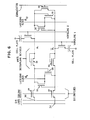
- FIG. 6 shows a different embodiment of a decoupling technique using NMOS devices 50,52 in a folded bitline layout with bit switches 54,56 and an equalization device 58.
- NMOS devices 50,52 having their gates connected to the bitlines BL and IBLI, respectively, replace the grounded-gate PMOS devices 10,12 previously discussed.
- This decoupling device offers only a marginal improvement over the previous designs.
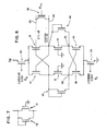
- FIG. 7 A new improved CMOS decoupling device is shown in FIG. 7. It is composed of a grounded-gate PMOS device such as devices 10 or 12 of the sense amplifiers of FIGS. 1, 2 and 3 in parallel with an NMOS device 48 whose gate is connected to its drain.
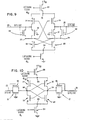
- the decoupling device of FIG. 7 is inserted in the bitlines or in the sense amplifiers of FIGS. 1, 2 and 3 as shown in FIGS. 8, 9 and 10 respectively.
- a write time approaching that of 1/2 VDD is achieved because the pull-down of the bitline is achieved through the NMOS pair 18,20 and PMOS pair 14,16 and is limited to the smaller threshold voltage of either NMOS or PMOS device.
- the bitline BL and BTls connected to the drain of the NMOS 48 and consequently the source-follower effect encountered with a grounded-gate PMOS device is eliminated.
- CMOS decoupling device requires that the bitline downward voltage swing should be less than the
- the sense amplifier latches, the source of the NMOS device 48 of the decoupling device goes to ground and its threshold voltage is not affected by the body effect and stays at its nominal value.
- a new decoupling device in combination with a sense amplifier for sensing with limited bitline swing has also been described.
- Important features of the new decoupling device include an NMOS device with a gate electrode connected to the memory bitline which functions as a decoupling device for sensing with limited bitline swing, and an NMOS device whose gate and drain electrodes are connected together in parallel with a grounded-gate PMOS device which also functions as a CMOS decoupling device serving the same purpose.
- the write time is significantly improved because of inclusion of an NMOS device approaching that of 1/2 VDD sensing.
- the downward bitline swing is limited to VTN, which is lower than IVTFI of the transfer device of the memory cell with no loss of the "0" signal.
Landscapes
- Engineering & Computer Science (AREA)
- Microelectronics & Electronic Packaging (AREA)
- Computer Hardware Design (AREA)
- Dram (AREA)
Abstract

Description
- The present invention relates generally to sense amplifiers, and more particularly to complementary metal-oxide-silicon field effect transistor (CMOS-FET) sense amplifiers for readout of dynamic random access memory (DRAM) integrated circuit structures.
- The prior art contains many references describing various memory-array sense amplifiers using complementary metal oxide semiconductor devices such as field effect transistors (CMOS-FETs).
- Examples of such references are provided in the following patents.
- U.S. Patent 4,169,233 issued September 25, 1979, to Haraszti, entitled HIGH PERFORMANCE CMOS AMPLIFIER, describes a sense amplifier circuit fabricated from complementary metal oxide semiconductor field effect transistors (CMOS-FETs) for applications in a radiation hardened environment. The sense amplifier is characterized by high sensitivity, high gain, good noise immunity, low power dissipation, fast operation, relatively small geometrical size, and good stabilization for temperature and supply effects while providing self- compensation for non-uniformities of electrical parameters which may occur as the result of MOS device processing or exposure to a nuclear radiation event. The sense amplifier circuit of FIG. 6 of the patent includes added transistors Q27 and Q29, but for purposes distinct from the present invention.
- U.S. Patent 4,375,600 issued March 1, 1983 to Wu, entitled SENSE AMPLIFIER FOR MEMORY ARRAY, describes a memory-array sense amplifier that includes a grounded-gate depletion-mode FET connected between a bitline and a sense node. Another FET connects a supply voltage VDD to the sense node when turned on by a clock phase signal. Further FETs form a latch circuit.
- U.S. Patent 4,262,341 issued April 14, 1981 to Mogi et al, entitled MEMORY CIRCUIT, relates to the addition of a capacitor circuit for augmenting the voltages at predetermined points in a sense amplifying circuit, in order to ensure a satisfactory refreshing of memory cells, since, if the potentials at the connecting points between a sense amplifying circuit and bitlines fall below a predetermined value when the sense amplifying circuit is caused to operate, it is difficult to achieve a complete refreshing of the memory cells. Transistors 01 and Q2 can disconnect the bitlines from being discharged during development of sensed valued in transistors Q3 and Q4.
- U.S. Patent 4,069,474 issued January 17, 1978 to Boettcher et al, entitled MOS RANDOM ACCESS MEMORY HAVING AN IMPROVED SENSING CIRCUIT, discloses a memory circuit wherein first and second bitline portions, each having a plurality of memory cells coupled thereto are provided for reading and writing electrical potentials into and out of the coupled memory cells. A bistable flip-flop type sensing amplifier is coupled between the first and second bit portion for sensing the voltage difference therebetween and for latching into one of the two states in response to sensing either a "0" or a "1" accessed to one of the bitline portions from an addressed memory cell to be read out of the memory.
- In U.S. Patent 4,236,231 issued November 25, 1980 to Taylor and entitled PROGRAMMABLE THRESHOLD SWITCHABLE RESISTIVE MEMORY CELL ARRAY, a memory-array is described wherein each memory cell includes a pair of threshold resistive elements which switch from a high to a low resistance state when a potential above their respective programmable thresholds is applied. A binary value is stored by creating a threshold difference between the two resistive elements using two different value current sources. The binary value stored is read by applying a ramp potential and determining which threshold resistive element switched states first using a sense latch.
- U.S. Patent 4,247,791 issued January 27, 1981 to Rovell, entitled CMOS MEMORY SENSE AMPLIFIER, discloses a complementary metal oxide semiconductor (CMOS) field effect transistor (FET) memory sense amplifier to detect a relatively small differential voltage that is superimposed on a relatively large common mode precharge signal. The sense amplifier is implemented so as to provide latched output signals after a short time delay and in response to sensed input signals that are supplied via a pair of data bus lines.
- U.S. Patent 4,354,257 issued October 12, 1982 to Varshney et al, entitled SENSE AMPLIFIER FOR CCD MEMORY, describes a sense amplifier for use with a charge coupled device in which capacitive coupled charge is employed with a flip-flop circuit to accelerate sense and readout. Operation of the amplifier is effected with two external clocks and two internally generated clocks.
- U.S. Patent 4,421,996 issued December 20, 1983 to Chuang et al, entitled SENSE AMPLIFICATION SCHEME FOR RANDOM ACCESS MEMORY, describes a source-clocked type of cross-coupled latch sense amplifier of a dynamic random access memory device including a sense clock that employs multiple extended dummy memory cells to provide reference timing which tracks time constants of word line, cell transfer gate, cell capacitor, and bitline, and the sense clock is further compensated over large variations of fabrication process parameters and operating conditions. The trigger and slave clock circuit are chained in series to control the timing sequence of a plurality of clocked output signals. The clocked output signals are selectively amplified and summed in parallel to generate current with an intended dynamic characteristic. The current so generated is applied to the common source electrodes of the cross-coupled latch.
- In U.S. Patent 3,949,381 issued April 6, 1976 to Dennard et al, entitled DIFFERENTIAL CHARGE TRANSFER SENSE AMPLIFIER, a differential charge transfer amplifier, which functions as a sensing and regenerating circuit responsive to binary information represented by the level of charge in a stored charge memory cell is disclosed.
- U.S. Patent 3,879,621 issued April 18, 1973 to Cavaliere et al, entitled SENSE AMPLIFIER, discloses an FET sense amplifier for converting a double rail differential memory output signal to a full logic output signal, the amplifier comprising first and second pairs of FETs coupled together at a pair of common nodes. In one embodiment, first and second field effect transistors of the same conductive type are connected to respective ones of the nodes. A third field effect transistor of a second conductive type is connected to one of the pairs of FETs, the first, second and third field effect transistors are interconnected so that when the first and second transistors conduct the third transistor is cut off, and when the first and second transistors are cut off, the third transistor conducts.
- U.S. Patent 3,671,772 issued June 20, 1972 to Henle, entitled DIFFERENCE AMPLIFIER, discloses a difference amplifier used as a sense amplifier for stored binary data being read from a computer memory. The amplifier includes a pair of cross-coupled transistors, a power source providing an operating voltage for said transistors, and means for intermittently applying said power source to the cross-coupled transistors. Selective application means apply each of the pair of voltage signals to be differentiated from each other to a respective one of the pair of cross-couplings, i.e., the pair of cross-connected regions in the transistors. In the case of reading from binary storage, the voltage signals are applied from the pair of sense lines from the memory storage. The signals are applied during a period when the voltage source is not being applied and, consequently, both of the paired transistors are in the non-conductive state. The signals establish a stored charge in each of the transistors; the difference between these charges will determine which of the transistors assumes the conductive state when the power is subsequently applied.
- U.S. Patent 3,648,071 issued March 7, 1972 to Mrazek, entitled HIGH-SPEED MOS SENSE AMPLIFIER, relates to an improved sense amplifier comprised of an all FET amplifying circuit having means for limiting the voltage swing of the read potential applied thereby to an integrated circuit memory array in sensing the stored "1" and "0" memory states. The amplifier includes upper and lower output level-limiting circuits which detect predetermined signal levels in the output signal of the amplifier and cause the impedences at the input of the amplifier to be adjusted to limit the output signal swing of the amplifier to within the predetermined signal leads. In so doing, the memory read potential is also constrained to swing within certain predetermined limits.
- U.S. Patent 3,560,765 issued February 2, 1971 to Kubinec, entitled HIGH SPEED MOS READ-ONLY MEMORY, describes a sense-amplifier for use with a read-only memory apparatus and having means for limiting to less than six volts, the voltage to which the memory elements are subjected. An all FET amplifier structure is provided having an input stage which clamps the output voltage of the memory device to a predetermined potential and prevents the output of the memory from causing this potential to swing more than a predetermined value when a storage element is gated ON.
- U.S. Patent 4,053,873 issued October 11, 1977. to Freeman et al, entitled SELF-ISOLATING CROSS-COUPLED SENSE AMPLIFIER LATCH CIRCUIT, discloses a self-isolating cross-coupled sense amplifier latch circuit having five enhancement mode field effect transistor devices and two depletion mode field effect transistor devices. The first and second field effect transistors from a cross-coupled pair with true and complement outputs being available at the cross-coupled nodes. A third field effect transistor is connected to a common connection between the source electrodes of the cross-coupled pair and is used to establish a race condition after a small. difference in potential has been applied to the aforementioned output nodes. A pair of depletion mode devices are connected as diodes between a positive potential (VH) and each of the output nodes, respectively. Each of the output nodes is connected to a respective bitline of a column of memory cells through enhancement mode field effect transistors connected as third and fourth unidirectionally conducting devices.
- U.S. Patent 3,789,312 issued January 29, 1974 to Heller et al, entitled THRESHOLD INDEPENDENT LINEAR AMPLIFIER, describes a system wherein low level pulses in the order of 100 millivolts or less can be detected and amplified regardless of variations in the voltage required to turn on the active device used in the amplifier. This is achieved by coupling an active device between a capacitor and a capacitively loaded output line, charging the output line to a reference voltage. applying a level setting voltage to the device to turn on the device; charging the capacitor to a voltage substantially equivalent to the level setting voltage to turn off the device while maintaining it such that any input signal superimposed on the level setting voltage will cause the device to again turn on and discharge the capacitively loaded output line thereby amplifying and inverting the superimposed input signal.
- The invention as claimed is to provide a sense amplifier for integrated circuit memories which offers improved sensing speed without increased power consumption and unsymmetrical bitline voltage swing. The sense amplifier also includes a novel decoupling structure to provide improved restoring and writing time. Further unique structural features of the improved sense amplifier include the provision of grounded- gate PMOS devices for the cross-coupled sense amplifier for voltage clamping and/or a decoupling structure incorporating an NMOS device having gate and drain elements connected together in parallel with a grounded-gate PMOS device.
- The invention is described in more detail by specific embodiments in connection with drawings.
-
- FIG. 1 is a schematic circuit diagram of one embodiment of a sense amplifier according to the principles of the present invention.
- FIGS. 2, 3, 4 and 5 illustrate schematic alternate embodiments of sense amplifiers according to the principles of the present invention.
- FIG. 6 shows a schematic circuit diagram of one embodiment of decoupling devices for a sense amplifier.
- FIG. 7 illustrates a schematic circuit of an improved decoupling structure for sense amplifiers according to the principles of the present invention.
- FIGS. 8 and 9 show schematic circuit diagrams of the decoupling structure of FIG. 7 incorporated into the sense amplifier embodiments of FIGS. 2 and 3, respectively.
- In a dynamic ram access memory (DRAM), bitlines are precharged to a certain level before sensing starts. The optimum precharge voltage level in each situation depends on the design and technology used for the specific DRAM employed. In presently employed technology using p-array devices in an n-well, precharging the bitlines higher than 1/2 VDD improves the sensing speed, but the increased power consumption and the resulting unsymmetrical bitline voltage swing are major drawbacks.
- In the present invention, a novel sense amplifier is provided which solves these drawbacks with an improved sensing speed. In an embodiment of the sense amplifier of the present invention illustrated in FIG. 1, two
PMOS devices cross-coupled PMOS devices cross-coupled NMOS devices sense amplifier node 36 is connected to the power supply VDD viaPMOS latching device 22 andnode 38 is connected to reference potential (ground) viaNMOS latching device 24. Latching clocks φs and φsp are applied todevices bitline 26 andbitline equalization device 30 through an equalization clock oq. The gates ofdevices grounded-gate PMOS devices devices devices -

nodes 
PMOS devices NMOS devices - The present invention is not limited to the embodiment of the sense amplifier shown in FIG. 1. Other embodiments of the invention are illustrated in FIGS. 2, 3, 4 and 5. The PMOS devices and NMOS devices which are functionally equivalent to those of FIG. 1 are given the same reference numbers in FIGS. 2, 3, 4 and 5.
- In the embodiments of FIGS. 2-5 as well as the embodiment of FIG. 1, the
node 36 is connected to aPMOS latching device 22. Thenode 38 in FIGS. 2 and 3 is connected to anNMOS latching device 24.Nodes 38 of FIGS. 4 and 5 are connected todevices nodes PMOS devices nodes grounded-gate PMOS devices nodes 32 andbitline 26 and betweennode 34 andbitline 28. In FIGS. 4 and 5, the latching devices 40 (FIG. 4) and 42 (FIG. 5) connected to thenode 38 are different than latchingdevice 24 shown in FIGS. 1, 2 and 3, respectively. ThePMOS latching device 40 used in the embodiment of FIG. 4 in lieu of a conventionalNMOS latching device 24 limits the voltage swing of thenode 38 only to |VT| (absolute value of the threshold voltage) of thePMOS device 40 and consequently limits bitline swing to the VT of thePMOS device 40. In the embodiment of FIG. 5, avoltage source 44 is added in series with theNMOS latching device 42 and limits the lower swing of thenode 38 to the output voltage of thevoltage source 44. Thevoltage source 44 is of conventional design with its output less than the I VTJ of array devices. - The present invention also provides a unique CMOS decoupling device structure for combination with the


- For

grounded-gate PMOS devices devices grounded-gate PMOS devices 
PMOS devices NMOS devices grounded-gate PMOS devices - FIG. 6 shows a different embodiment of a decoupling technique using
NMOS devices equalization device 58. In this design,NMOS devices grounded-gate PMOS devices - A new improved CMOS decoupling device is shown in FIG. 7. It is composed of a grounded-gate PMOS device such as
devices NMOS device 48 whose gate is connected to its drain. For example, the decoupling device of FIG. 7 is inserted in the bitlines or in the sense amplifiers of FIGS. 1, 2 and 3 as shown in FIGS. 8, 9 and 10 respectively. With the new CMOS decoupling device, a write time approaching that of 1/2 VDD is achieved because the pull-down of the bitline is achieved through theNMOS pair PMOS pair NMOS 48 and consequently the source-follower effect encountered with a grounded-gate PMOS device is eliminated. - A proper operation of the CMOS decoupling device requires that the bitline downward voltage swing should be less than the |VTP| of the transfer device in a cell. Otherwise, the cell suffers a loss in the "O" signal. When the sense amplifier latches, the source of the
NMOS device 48 of the decoupling device goes to ground and its threshold voltage is not affected by the body effect and stays at its nominal value. - By designing |VTP| of the transfer device higher than the nominal threshold voltage of the NMOS device, the bitline is clamped below the |VTP| of the transfer device.
- Thus, a new decoupling device in combination with a sense amplifier for


Claims (10)
wherein said first and second bitlines conduct bitline voltage signals thereon having magnitudes of voltage variations limited by said first and second voltage limiting transistors.
Applications Claiming Priority (2)
| Application Number | Priority Date | Filing Date | Title |
|---|---|---|---|
| US07/095,061 US4816706A (en) | 1987-09-10 | 1987-09-10 | Sense amplifier with improved bitline precharging for dynamic random access memory |
| US95061 | 2005-03-31 |
Publications (3)
| Publication Number | Publication Date |
|---|---|
| EP0306712A2 true EP0306712A2 (en) | 1989-03-15 |
| EP0306712A3 EP0306712A3 (en) | 1991-03-27 |
| EP0306712B1 EP0306712B1 (en) | 1993-12-29 |
Family
ID=22249130
Family Applications (1)
| Application Number | Title | Priority Date | Filing Date |
|---|---|---|---|
| EP88112792A Expired - Lifetime EP0306712B1 (en) | 1987-09-10 | 1988-08-05 | Sense amplifier with improved bitline precharging for dynamic random access memory |
Country Status (4)
| Country | Link |
|---|---|
| US (1) | US4816706A (en) |
| EP (1) | EP0306712B1 (en) |
| JP (1) | JPS6472395A (en) |
| DE (1) | DE3886632T2 (en) |
Cited By (7)
| Publication number | Priority date | Publication date | Assignee | Title |
|---|---|---|---|---|
| EP0426071A2 (en) * | 1989-10-30 | 1991-05-08 | Matsushita Electronics Corporation | Semiconductor memory apparatus |
| GB2294143A (en) * | 1994-10-11 | 1996-04-17 | Townsend & Townsend & Crew Llp | Sense amplifier |
| GB2300289A (en) * | 1995-04-28 | 1996-10-30 | Samsung Electronics Co Ltd | Current sense amplifier for a semiconductor memory |
| GB2328538A (en) * | 1994-10-11 | 1999-02-24 | Townsend & Townsend & Crew Llp | Sense amplifier |
| EP0903746A1 (en) * | 1997-09-23 | 1999-03-24 | STMicroelectronics SA | Device and procedure for reading/rewriting a dynamic memory cell |
| WO2000074065A1 (en) * | 1999-05-28 | 2000-12-07 | Lockheed Martin Corporation | Method and apparatus for hardening a static random access memory cell from single event upsets |
| US6218505B1 (en) | 1996-04-23 | 2001-04-17 | Biosearch Italia S.P.A. | Chemical process for preparing amide derivatives of antibiotic A 40926 |
Families Citing this family (53)
| Publication number | Priority date | Publication date | Assignee | Title |
|---|---|---|---|---|
| US5029136A (en) * | 1987-11-25 | 1991-07-02 | Texas Instruments Incorporated | High-speed DRAM sense amp with high noise immunity |
| US5053652A (en) * | 1988-01-28 | 1991-10-01 | Hitachi, Ltd. | High speed sensor system using a level shift circuit |
| US5148399A (en) * | 1988-06-28 | 1992-09-15 | Oki Electric Industry Co., Ltd. | Sense amplifier circuitry selectively separable from bit lines for dynamic random access memory |
| JPH0727717B2 (en) * | 1988-07-13 | 1995-03-29 | 株式会社東芝 | Sense circuit |
| JPH07111830B2 (en) * | 1989-01-12 | 1995-11-29 | 松下電器産業株式会社 | Semiconductor memory device |
| US4991142A (en) * | 1989-07-20 | 1991-02-05 | Samsung Semiconductor Inc. | Dynamic random access memory with improved sensing and refreshing |
| US5023480A (en) * | 1990-01-04 | 1991-06-11 | Digital Equipment Corporation | Push-pull cascode logic |
| US5293338A (en) * | 1990-02-22 | 1994-03-08 | Sharp Kabushiki Kaisha | Peripheral circuit in a dynamic semiconductor memory device enabling a time-saving and energy-saving data readout |
| US5426610A (en) * | 1990-03-01 | 1995-06-20 | Texas Instruments Incorporated | Storage circuitry using sense amplifier with temporary pause for voltage supply isolation |
| JPH0492287A (en) * | 1990-08-08 | 1992-03-25 | Internatl Business Mach Corp <Ibm> | Dynamic-random-access-memory |
| DE4039996A1 (en) * | 1990-10-31 | 1992-05-07 | Nattermann A & Cie | METHOD FOR PRODUCING PHOSPHATIDYLCHOLINE DERIVATIVES |
| US5304874A (en) * | 1991-05-31 | 1994-04-19 | Thunderbird Technologies, Inc. | Differential latching inverter and random access memory using same |
| US5305269A (en) * | 1991-05-31 | 1994-04-19 | Thunderbird Technologies, Inc. | Differential latching inverter and random access memory using same |
| US5280452A (en) * | 1991-07-12 | 1994-01-18 | International Business Machines Corporation | Power saving semsing circuits for dynamic random access memory |
| US5162680A (en) * | 1991-12-17 | 1992-11-10 | Altera Corporation | Sense amplifier for programmable logic device |
| US5257232A (en) * | 1992-03-05 | 1993-10-26 | International Business Machines Corporation | Sensing circuit for semiconductor memory with limited bitline voltage swing |
| US5239503A (en) * | 1992-06-17 | 1993-08-24 | Aptix Corporation | High voltage random-access memory cell incorporating level shifter |
| US5315545A (en) * | 1992-06-17 | 1994-05-24 | Aptix Corporation | High-voltage five-transistor static random access memory cell |
| US5339274A (en) * | 1992-10-30 | 1994-08-16 | International Business Machines Corporation | Variable bitline precharge voltage sensing technique for DRAM structures |
| US5490156A (en) * | 1993-03-05 | 1996-02-06 | Cyrix Corporation | Cross-coupled parity circuit with charging circuitry to improve response time |
| JP3623004B2 (en) * | 1994-03-30 | 2005-02-23 | 松下電器産業株式会社 | Voltage level conversion circuit |
| US5526314A (en) * | 1994-12-09 | 1996-06-11 | International Business Machines Corporation | Two mode sense amplifier with latch |
| US5525923A (en) * | 1995-02-21 | 1996-06-11 | Loral Federal Systems Company | Single event upset immune register with fast write access |
| US5552728A (en) * | 1995-05-01 | 1996-09-03 | Cirrus Logic, Inc. | Latch-type current sense amplifier with self-regulating inputs |
| JPH0973791A (en) * | 1995-09-06 | 1997-03-18 | Fujitsu Ltd | Amplifier |
| US5818280A (en) * | 1995-12-11 | 1998-10-06 | International Business Machines Corporation | Method and apparatus with preconditioning for shifting the voltage level of a signal |
| US5717355A (en) * | 1995-12-11 | 1998-02-10 | International Business Machines Corporation | Method and apparatus with active feedback for shifting the voltage level of a signal |
| US5666320A (en) * | 1995-12-20 | 1997-09-09 | International Business Machines Corporation | Storage system |
| US5661684A (en) * | 1995-12-22 | 1997-08-26 | International Business Machines Corporation | Differential sense amplifier |
| US5742552A (en) * | 1996-10-31 | 1998-04-21 | Texas Instruments Incorporated | Timing control for clocked sense amplifiers |
| US5828239A (en) * | 1997-04-14 | 1998-10-27 | International Business Machines Corporation | Sense amplifier circuit with minimized clock skew effect |
| KR100298432B1 (en) * | 1998-05-19 | 2001-08-07 | 김영환 | Control Circuit for Controlling Power Consumption in Semiconductor Memory Device And Method Varying Bit-line Precharge Voltage Using the Same |
| US6420908B2 (en) * | 1999-01-05 | 2002-07-16 | Infineon Technologies Ag | Sense amplifier |
| KR100322539B1 (en) * | 1999-07-10 | 2002-03-18 | 윤종용 | Sense amplifying apparatus of semiconductor integrated circuit |
| US6285612B1 (en) | 2000-06-26 | 2001-09-04 | International Business Machines Corporation | Reduced bit line equalization level sensing scheme |
| US6794915B2 (en) * | 2000-11-10 | 2004-09-21 | Leonid B. Goldgeisser | MOS latch with three stable operating points |
| JP2002164750A (en) * | 2000-11-24 | 2002-06-07 | Nippon Precision Circuits Inc | Differential comparator circuit |
| DE60237966D1 (en) * | 2001-02-27 | 2010-11-25 | Broadcom Corp | FAST COMPARATORS WITH LOCKING LEVEL |
| US6831866B1 (en) | 2003-08-26 | 2004-12-14 | International Business Machines Corporation | Method and apparatus for read bitline clamping for gain cell DRAM devices |
| US7262639B2 (en) * | 2005-01-21 | 2007-08-28 | Broadcom Corporation | High-speed comparator |
| US7046565B1 (en) | 2005-02-22 | 2006-05-16 | International Business Machines Corporation | Bi-mode sense amplifier with dual utilization of the reference cells and dual precharge scheme for improving data retention |
| JP4707099B2 (en) * | 2005-08-23 | 2011-06-22 | ルネサスエレクトロニクス株式会社 | Differential output circuit |
| US7450455B2 (en) * | 2005-09-29 | 2008-11-11 | Hynix Semiconductor Inc. | Semiconductor memory device and driving method thereof |
| US7286425B2 (en) * | 2005-10-31 | 2007-10-23 | International Business Machines Corporation | System and method for capacitive mis-match bit-line sensing |
| US7342832B2 (en) * | 2005-11-16 | 2008-03-11 | Actel Corporation | Bit line pre-settlement circuit and method for flash memory sensing scheme |
| JP4901211B2 (en) * | 2005-12-26 | 2012-03-21 | 株式会社東芝 | Sense amplifier and semiconductor memory device |
| KR100734321B1 (en) * | 2006-06-27 | 2007-07-02 | 삼성전자주식회사 | Semiconductor memory device and driving method thereof |
| US7649216B1 (en) * | 2007-05-08 | 2010-01-19 | Arizona Board Of Regents For And On Behalf Of Arizona State University | Total ionizing dose radiation hardening using reverse body bias techniques |
| US8295112B2 (en) * | 2009-03-31 | 2012-10-23 | Taiwan Semiconductor Manufacturing Company, Ltd. | Sense amplifiers and exemplary applications |
| US8885416B2 (en) | 2013-01-30 | 2014-11-11 | Sandisk Technologies Inc. | Bit line current trip point modulation for reading nonvolatile storage elements |
| KR102178732B1 (en) * | 2013-12-20 | 2020-11-13 | 삼성전자주식회사 | Semiconductor device |
| US11037621B2 (en) * | 2018-12-26 | 2021-06-15 | Micron Technology, Inc. | Sensing techniques using a charge transfer device |
| US11295788B2 (en) * | 2019-08-13 | 2022-04-05 | Ememory Technology Inc. | Offset cancellation voltage latch sense amplifier for non-volatile memory |
Citations (2)
| Publication number | Priority date | Publication date | Assignee | Title |
|---|---|---|---|---|
| US4169233A (en) * | 1978-02-24 | 1979-09-25 | Rockwell International Corporation | High performance CMOS sense amplifier |
| EP0027169A1 (en) * | 1979-10-11 | 1981-04-22 | International Business Machines Corporation | Sense amplifier for integrated memory array |
Family Cites Families (17)
| Publication number | Priority date | Publication date | Assignee | Title |
|---|---|---|---|---|
| US3560765A (en) * | 1968-12-04 | 1971-02-02 | Nat Semiconductor Corp | High speed mos read-only memory |
| US3671772A (en) * | 1969-10-01 | 1972-06-20 | Ibm | Difference amplifier |
| US3648071A (en) * | 1970-02-04 | 1972-03-07 | Nat Semiconductor Corp | High-speed mos sense amplifier |
| US3789312A (en) * | 1972-04-03 | 1974-01-29 | Ibm | Threshold independent linear amplifier |
| US3879621A (en) * | 1973-04-18 | 1975-04-22 | Ibm | Sense amplifier |
| US3949381A (en) * | 1974-07-23 | 1976-04-06 | International Business Machines Corporation | Differential charge transfer sense amplifier |
| US4069474A (en) * | 1976-04-15 | 1978-01-17 | National Semiconductor Corporation | MOS Dynamic random access memory having an improved sensing circuit |
| US4053873A (en) * | 1976-06-30 | 1977-10-11 | International Business Machines Corporation | Self-isolating cross-coupled sense amplifier latch circuit |
| JPS5457921A (en) * | 1977-10-18 | 1979-05-10 | Fujitsu Ltd | Sense amplifier circuit |
| US4247791A (en) * | 1978-04-03 | 1981-01-27 | Rockwell International Corporation | CMOS Memory sense amplifier |
| US4236231A (en) * | 1979-10-09 | 1980-11-25 | Harris Corporation | Programmable threshold switchable resistive memory cell array |
| US4354257A (en) * | 1980-05-23 | 1982-10-12 | Fairchild Camera And Instrument Corporation | Sense amplifier for CCD memory |
| US4421996A (en) * | 1981-10-09 | 1983-12-20 | Advanced Micro Devices, Inc. | Sense amplification scheme for random access memory |
| US4551641A (en) * | 1983-11-23 | 1985-11-05 | Motorola, Inc. | Sense amplifier |
| US4627033A (en) * | 1984-08-02 | 1986-12-02 | Texas Instruments Incorporated | Sense amplifier with reduced instantaneous power |
| US4608670A (en) * | 1984-08-02 | 1986-08-26 | Texas Instruments Incorporated | CMOS sense amplifier with N-channel sensing |
| US4694205A (en) * | 1985-06-03 | 1987-09-15 | Advanced Micro Devices, Inc. | Midpoint sense amplification scheme for a CMOS DRAM |
-
1987
- 1987-09-10 US US07/095,061 patent/US4816706A/en not_active Expired - Fee Related
-
1988
- 1988-06-17 JP JP63148439A patent/JPS6472395A/en active Granted
- 1988-08-05 DE DE3886632T patent/DE3886632T2/en not_active Expired - Fee Related
- 1988-08-05 EP EP88112792A patent/EP0306712B1/en not_active Expired - Lifetime
Patent Citations (2)
| Publication number | Priority date | Publication date | Assignee | Title |
|---|---|---|---|---|
| US4169233A (en) * | 1978-02-24 | 1979-09-25 | Rockwell International Corporation | High performance CMOS sense amplifier |
| EP0027169A1 (en) * | 1979-10-11 | 1981-04-22 | International Business Machines Corporation | Sense amplifier for integrated memory array |
Cited By (16)
| Publication number | Priority date | Publication date | Assignee | Title |
|---|---|---|---|---|
| EP0426071A3 (en) * | 1989-10-30 | 1992-05-27 | Matsushita Electronics Corporation | Semiconductor memory apparatus |
| US5208771A (en) * | 1989-10-30 | 1993-05-04 | Matsushita Electronics Corporation | Semiconductor memory apparatus |
| EP0426071A2 (en) * | 1989-10-30 | 1991-05-08 | Matsushita Electronics Corporation | Semiconductor memory apparatus |
| GB2294143B (en) * | 1994-10-11 | 1999-04-14 | Townsend & Townsend & Crew Llp | Sense amplifier |
| GB2294143A (en) * | 1994-10-11 | 1996-04-17 | Townsend & Townsend & Crew Llp | Sense amplifier |
| US5585747A (en) * | 1994-10-11 | 1996-12-17 | Townsend & Townsend & Crew Llp | High speed low power sense amplifier |
| GB2328538A (en) * | 1994-10-11 | 1999-02-24 | Townsend & Townsend & Crew Llp | Sense amplifier |
| GB2328538B (en) * | 1994-10-11 | 1999-04-14 | Townsend & Townsend & Crew Llp | Sense amplifier |
| GB2300289A (en) * | 1995-04-28 | 1996-10-30 | Samsung Electronics Co Ltd | Current sense amplifier for a semiconductor memory |
| GB2300289B (en) * | 1995-04-28 | 1997-07-16 | Samsung Electronics Co Ltd | Current sense amplifier |
| US6218505B1 (en) | 1996-04-23 | 2001-04-17 | Biosearch Italia S.P.A. | Chemical process for preparing amide derivatives of antibiotic A 40926 |
| EP0903746A1 (en) * | 1997-09-23 | 1999-03-24 | STMicroelectronics SA | Device and procedure for reading/rewriting a dynamic memory cell |
| US5936904A (en) * | 1997-09-23 | 1999-08-10 | Sgs-Thomson Microelectronics S.A. | Device and process for reading/rewriting a dynamic random access memory cell |
| FR2768847A1 (en) * | 1997-09-23 | 1999-03-26 | St Microelectronics Sa | DEVICE AND METHOD FOR READING / REWRITING A DYNAMIC LIVE MEMORY CELL |
| WO2000074065A1 (en) * | 1999-05-28 | 2000-12-07 | Lockheed Martin Corporation | Method and apparatus for hardening a static random access memory cell from single event upsets |
| US6285580B1 (en) | 1999-05-28 | 2001-09-04 | Bae Systems Information | Method and apparatus for hardening a static random access memory cell from single event upsets |
Also Published As
| Publication number | Publication date |
|---|---|
| EP0306712A3 (en) | 1991-03-27 |
| DE3886632D1 (en) | 1994-02-10 |
| JPS6472395A (en) | 1989-03-17 |
| US4816706A (en) | 1989-03-28 |
| JPH0583998B2 (en) | 1993-11-30 |
| EP0306712B1 (en) | 1993-12-29 |
| DE3886632T2 (en) | 1994-06-23 |
Similar Documents
| Publication | Publication Date | Title |
|---|---|---|
| EP0306712B1 (en) | Sense amplifier with improved bitline precharging for dynamic random access memory | |
| US5023841A (en) | Double stage sense amplifier for random access memories | |
| US4804871A (en) | Bit-line isolated, CMOS sense amplifier | |
| US6134164A (en) | Sensing circuit for a memory cell array | |
| US5237533A (en) | High speed switched sense amplifier | |
| US7460387B2 (en) | eDRAM hierarchical differential sense amp | |
| KR100258277B1 (en) | Four device sram cell with single bitline | |
| US4239993A (en) | High performance dynamic sense amplifier with active loads | |
| US4947376A (en) | Charge-transfer sense amplifier for dram and operating method therefor | |
| US3983543A (en) | Random access memory read/write buffer circuits incorporating complementary field effect transistors | |
| US4031522A (en) | Ultra high sensitivity sense amplifier for memories employing single transistor cells | |
| US5457657A (en) | High-speed sense amplifier having feedback loop | |
| US5416371A (en) | Sense system for dynamic random access memory | |
| EP0124868B1 (en) | Semiconductor memory | |
| US6212094B1 (en) | Low power SRAM memory cell having a single bit line | |
| JPS5931155B2 (en) | sense amplifier circuit | |
| JP2660454B2 (en) | CMOS precharge and equalization circuit | |
| US4598389A (en) | Single-ended CMOS sense amplifier | |
| US4860257A (en) | Level shifter for an input/output bus in a CMOS dynamic ram | |
| JPS60211693A (en) | Mos amplifier circuit | |
| EP0184031B1 (en) | Highly sensitive high performance sense amplifier | |
| US4298960A (en) | Memory integrated circuit | |
| JP2752197B2 (en) | Digital memory system | |
| JP2937719B2 (en) | Semiconductor storage device | |
| US4370575A (en) | High performance dynamic sense amplifier with active loads |
Legal Events
| Date | Code | Title | Description |
|---|---|---|---|
| PUAI | Public reference made under article 153(3) epc to a published international application that has entered the european phase |
Free format text: ORIGINAL CODE: 0009012 |
|
| AK | Designated contracting states |
Kind code of ref document: A2 Designated state(s): DE FR GB |
|
| 17P | Request for examination filed |
Effective date: 19890720 |
|
| PUAL | Search report despatched |
Free format text: ORIGINAL CODE: 0009013 |
|
| AK | Designated contracting states |
Kind code of ref document: A3 Designated state(s): DE FR GB |
|
| 17Q | First examination report despatched |
Effective date: 19920520 |
|
| GRAA | (expected) grant |
Free format text: ORIGINAL CODE: 0009210 |
|
| AK | Designated contracting states |
Kind code of ref document: B1 Designated state(s): DE FR GB |
|
| REF | Corresponds to: |
Ref document number: 3886632 Country of ref document: DE Date of ref document: 19940210 |
|
| ET | Fr: translation filed | ||
| PLBE | No opposition filed within time limit |
Free format text: ORIGINAL CODE: 0009261 |
|
| STAA | Information on the status of an ep patent application or granted ep patent |
Free format text: STATUS: NO OPPOSITION FILED WITHIN TIME LIMIT |
|
| 26N | No opposition filed | ||
| PGFP | Annual fee paid to national office [announced via postgrant information from national office to epo] |
Ref country code: GB Payment date: 19950726 Year of fee payment: 8 |
|
| PGFP | Annual fee paid to national office [announced via postgrant information from national office to epo] |
Ref country code: FR Payment date: 19950807 Year of fee payment: 8 |
|
| PG25 | Lapsed in a contracting state [announced via postgrant information from national office to epo] |
Ref country code: GB Effective date: 19960805 |
|
| PGFP | Annual fee paid to national office [announced via postgrant information from national office to epo] |
Ref country code: DE Payment date: 19960828 Year of fee payment: 9 |
|
| GBPC | Gb: european patent ceased through non-payment of renewal fee |
Effective date: 19960805 |
|
| PG25 | Lapsed in a contracting state [announced via postgrant information from national office to epo] |
Ref country code: FR Effective date: 19970430 |
|
| REG | Reference to a national code |
Ref country code: FR Ref legal event code: ST |
|
| PG25 | Lapsed in a contracting state [announced via postgrant information from national office to epo] |
Ref country code: DE Free format text: LAPSE BECAUSE OF NON-PAYMENT OF DUE FEES Effective date: 19980501 |