EP0306399B1 - Abgedeckte Leuchte für Kraftfahrzeuge - Google Patents
Abgedeckte Leuchte für Kraftfahrzeuge Download PDFInfo
- Publication number
- EP0306399B1 EP0306399B1 EP88402180A EP88402180A EP0306399B1 EP 0306399 B1 EP0306399 B1 EP 0306399B1 EP 88402180 A EP88402180 A EP 88402180A EP 88402180 A EP88402180 A EP 88402180A EP 0306399 B1 EP0306399 B1 EP 0306399B1
- Authority
- EP
- European Patent Office
- Prior art keywords
- screen
- bands
- lamp
- lens elements
- optical
- Prior art date
- Legal status (The legal status is an assumption and is not a legal conclusion. Google has not performed a legal analysis and makes no representation as to the accuracy of the status listed.)
- Expired - Lifetime
Links
- 230000003287 optical effect Effects 0.000 claims description 32
- 239000000463 material Substances 0.000 claims description 7
- 238000009826 distribution Methods 0.000 claims description 5
- 238000004040 coloring Methods 0.000 claims description 3
- 238000000926 separation method Methods 0.000 claims description 3
- 239000012780 transparent material Substances 0.000 claims description 2
- 238000011144 upstream manufacturing Methods 0.000 claims description 2
- 239000011521 glass Substances 0.000 description 4
- 238000003892 spreading Methods 0.000 description 4
- 230000001105 regulatory effect Effects 0.000 description 3
- 238000009304 pastoral farming Methods 0.000 description 2
- 230000015572 biosynthetic process Effects 0.000 description 1
- 239000003086 colorant Substances 0.000 description 1
- 238000009792 diffusion process Methods 0.000 description 1
- 239000006185 dispersion Substances 0.000 description 1
- 230000000694 effects Effects 0.000 description 1
- 238000004519 manufacturing process Methods 0.000 description 1
- 230000003014 reinforcing effect Effects 0.000 description 1
- 230000011664 signaling Effects 0.000 description 1
Images
Classifications
-
- F—MECHANICAL ENGINEERING; LIGHTING; HEATING; WEAPONS; BLASTING
- F21—LIGHTING
- F21S—NON-PORTABLE LIGHTING DEVICES; SYSTEMS THEREOF; VEHICLE LIGHTING DEVICES SPECIALLY ADAPTED FOR VEHICLE EXTERIORS
- F21S43/00—Signalling devices specially adapted for vehicle exteriors, e.g. brake lamps, direction indicator lights or reversing lights
- F21S43/20—Signalling devices specially adapted for vehicle exteriors, e.g. brake lamps, direction indicator lights or reversing lights characterised by refractors, transparent cover plates, light guides or filters
- F21S43/2605—Refractors
- F21S43/2641—Refractors or refracting portions characterised by their relative arrangement, e.g. parallel refractors
- F21S43/26411—Two or more successive refractors
-
- F—MECHANICAL ENGINEERING; LIGHTING; HEATING; WEAPONS; BLASTING
- F21—LIGHTING
- F21S—NON-PORTABLE LIGHTING DEVICES; SYSTEMS THEREOF; VEHICLE LIGHTING DEVICES SPECIALLY ADAPTED FOR VEHICLE EXTERIORS
- F21S43/00—Signalling devices specially adapted for vehicle exteriors, e.g. brake lamps, direction indicator lights or reversing lights
- F21S43/20—Signalling devices specially adapted for vehicle exteriors, e.g. brake lamps, direction indicator lights or reversing lights characterised by refractors, transparent cover plates, light guides or filters
- F21S43/2605—Refractors
- F21S43/2621—Refractors characterised by the properties of the light beam shaping surface
- F21S43/26231—Refractors characterised by the properties of the light beam shaping surface collimating, focusing, condensing or projecting beams, e.g. projection lenses or Fresnel lenses
-
- F—MECHANICAL ENGINEERING; LIGHTING; HEATING; WEAPONS; BLASTING
- F21—LIGHTING
- F21S—NON-PORTABLE LIGHTING DEVICES; SYSTEMS THEREOF; VEHICLE LIGHTING DEVICES SPECIALLY ADAPTED FOR VEHICLE EXTERIORS
- F21S43/00—Signalling devices specially adapted for vehicle exteriors, e.g. brake lamps, direction indicator lights or reversing lights
- F21S43/20—Signalling devices specially adapted for vehicle exteriors, e.g. brake lamps, direction indicator lights or reversing lights characterised by refractors, transparent cover plates, light guides or filters
- F21S43/281—Materials thereof; Structures thereof; Properties thereof; Coatings thereof
- F21S43/2817—Coatings, e.g. anti-reflection coatings
Definitions
- the invention relates to a motor vehicle light comprising at least one lamp, a reflection or refraction element arranged in correspondence with this lamp to reflect or refract light in the form of a beam of substantially parallel rays, an intermediate screen arranged in front of the lamp and of the reflection or refraction element chosen and formed by a plate of transparent material of which, on the one hand, the internal face is provided with convergence dioptres each aligned on one of the transparent zones arranged on the external face of the intermediate screen which, on the other hand, is covered with an opaque mask provided on the same alignment with orifices for the passage of the brushes of light concentrated by said dioptres, a front covering screen closing off the whole at the front of said light and provided with an optic spreading and distributing as appropriate said elementary brushes to form the lighting beam or external signage expected.
- an arrangement of this kind is produced in numerous automotive signaling lights in which the covering screen has an arrangement of vertical and horizontal diffusion dioptres under the general shape of spherical caps (balls) and / or tori on its internal surface, (preferably in the crossed arrangement of parallel cylindrical lenses on each of the two faces of the covering screen set out in the aforementioned patent), dioptres which reinforce the divergence of the elementary light brushes at the outlet of the orifices of the mask in order to achieve the required spreading of the external lighting beam.
- the present invention aims to achieve a masked type fire mentioned in the introduction, but capable of meeting the style requirements mentioned above.
- the fire according to the invention is characterized by the fact that said convergence diopters are arranged so as to focus forward the parallel incident rays which the intermediate screen receives from the chosen upstream reflection and / or refraction means of the lamp rays, the intermediate screen being provided on its outer wall of a corresponding arrangement of diverging diopters on the one hand positioned in the axis of each of the converging diopters and capable of enveloping the entire convergent volume of each functional light brush focused by said convergence dioptres, and of straightening above all their elementary rays in a direction substantially parallel to the original incident rays, on the other hand located in very slight withdrawal from the flat surface and / or radiated by substantially vertical bands regulating the external relief of the external wall of the intermediate screen which is itself covered, with a layer of opaque material, which masks in external vision, extinguished fire, a coloring element chosen from the functional light beam and determines in the alignment axis of each of the above-mentioned convergence and diverg
- the light passage orifices of the mask of opaque material of the intermediate screen consist of grooves of small width separating between them the various bands of optical appearance which regulate the relief of the external wall of said intermediate screen, and at the bottom of which grooves are made substantially set back the righting diopters, said bands accentuating the pitch of the aspect relief of the optical elements of the covering screen which is seen from the outside.
- the dioptres of divergence of the intermediate screen produced in very slight withdrawal from the flat and / or radiated surface of the bands of optical appearance regulating the external relief of said screen are arranged according to a generatrix of this surface other than the generator defining the joint ownership of said strips directly juxtaposed between them and of width and vertical orientation substantially identical to those of the optical strips of the front covering screen so as to accentuate the virtual depth of the relief of the covering optics seen from outside the fire.
- the diverging diopters of the intermediate screen produced in very slight withdrawal from the flat and / or radiated surface of the bands of optical appearance regulating the external relief of said screen, are arranged according to a generator of this surface other than the generator. delimiting the joint ownership of said bands directly juxtaposed between them and of vertical orientation substantially identical to that of the optical strips of the front overlay screen but of different width to either accentuate part of the virtual resulting pitch or to locally accentuate the virtual depth thereof in order to simulate lines of separation of various optical zones of the same appearance as those separating the different optical zones of the windows of a neighboring lighting device such as a projector.
- the intermediate screen and / or the covering screen are positioned orthogonally to the horizontal light positioning plane.
- the intermediate screen and / or the covering screen are inclined to the horizontal plane for positioning the light to further mask the righting diopters from the influence of the sun's rays radiating from the outside.
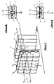
- FIGS. 1 and 2 describe a first embodiment of the invention.
- the diverging diopters 3 are each coaxial with a convergence diopter 2 and are dimensioned so as to envelop the whole of the light brush focused by the corresponding convergence diopter and to straighten this brush, comprised between the elementary rays C1- C2, in a beam substantially parallel to the incident rays I1-I2.
- the diverging diopters 3 are located slightly recessed with respect to substantially vertical bands 4 also formed on the outer wall of the screen 1.
- This screen 1 is, on its outer wall, covered with a layer of opaque material 5 intended to hide from the outside of the light the coloring member (not shown) of the incident beam, when the light is not on.
- the opaque material 5 is interrupted locally opposite the diverging diopters 3 to form passage orifices for the elementary rays i1-i2 originating from these diopters 3.
- the substantially parallel beams of rays thus formed strike a transparent front covering screen 6 which forms the front glass of the fire.
- the inner wall of the screen 6 is provided with substantially vertical juxtaposed strips 7 formed from flat and / or radiated optical elements which transmit rays r coming from the elementary incident rays i1-i2 to the outside.
- the width of the bands 7 is such that their relief is accentuated by the external relief bands 4 of the intermediate screen 1.
- the pitch and the depth of the optical elements of the strips 7 are adjusted to obtain the desired spreading and distribution of the external lighting beam r and to visually adapt to the glass next to another lighting device, in particular d 'a projector or headlight.
- the passage orifices formed in the mask of opaque material 5 are formed by grooves of small width 8 which accentuate the pitch of the strips of optical elements 7 of the covering screen 6.
- the diverging diopters 3 are arranged along generatrices of the intermediate screen 1 distinct from the generatrices delimiting the bands 4 of the screen 1, these bands 4 being directly juxtaposed with one another with a width and vertical orientation substantially identical to those of the strips 7 of the covering screen 6. It is thus possible to accentuate the apparent depth of the covering optics.
- the strips 4 directly juxtaposed between them and substantially vertical have a width different from that of the strips 7 of the cover screen 6. It is thus possible to simulate separation lines reinforcing the resemblance to the ice d 'an adjacent projector.
- the intermediate screen 1 is orthogonal to the horizontal positioning plane H of the light.
- the cover screen 6 can also occupy such an orthogonal position.
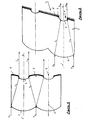
- the intermediate screen 1 (FIG. 5) and / or the covering screen 6 are inclined on the horizontal plane H for positioning the light, in order to hide more the dioptres of divergence 3 compared to the grazing solar rays S coming from outside.
Landscapes
- Engineering & Computer Science (AREA)
- General Engineering & Computer Science (AREA)
- Non-Portable Lighting Devices Or Systems Thereof (AREA)
Claims (6)
Applications Claiming Priority (2)
| Application Number | Priority Date | Filing Date | Title |
|---|---|---|---|
| FR8712238A FR2620197B1 (fr) | 1987-09-03 | 1987-09-03 | Feu masque pour vehicules automobiles |
| FR8712238 | 1987-09-03 |
Publications (2)
| Publication Number | Publication Date |
|---|---|
| EP0306399A1 EP0306399A1 (de) | 1989-03-08 |
| EP0306399B1 true EP0306399B1 (de) | 1991-09-04 |
Family
ID=9354597
Family Applications (1)
| Application Number | Title | Priority Date | Filing Date |
|---|---|---|---|
| EP88402180A Expired - Lifetime EP0306399B1 (de) | 1987-09-03 | 1988-08-30 | Abgedeckte Leuchte für Kraftfahrzeuge |
Country Status (3)
| Country | Link |
|---|---|
| EP (1) | EP0306399B1 (de) |
| DE (1) | DE3864635D1 (de) |
| FR (1) | FR2620197B1 (de) |
Cited By (1)
| Publication number | Priority date | Publication date | Assignee | Title |
|---|---|---|---|---|
| FR3163711A1 (fr) * | 2024-06-19 | 2025-12-26 | Valeo Vision | Module lumineux d’un dispositif lumineux pour véhicule |
Families Citing this family (6)
| Publication number | Priority date | Publication date | Assignee | Title |
|---|---|---|---|---|
| DE4003905C1 (en) * | 1990-02-09 | 1991-07-25 | Stuehrenberg Gmbh, 4930 Detmold, De | Phantom light suppressor for signal lamp with reflector - has ambient light absorber in emergent light beams region of dispersion lenses |
| FR2745062B1 (fr) * | 1996-02-16 | 1998-05-07 | Valeo Vision | Feu de signalisation comportant des rangees d'elements optiques et des bandes opaques ou semi-opaques |
| FR2753776B1 (fr) * | 1996-09-20 | 1998-12-11 | Feu de signalisation a miroir a surface a stries | |
| FR3054022B1 (fr) | 2016-07-18 | 2020-03-20 | Valeo Vision Belgique | Module lumineux pour vehicule automobile |
| CN107016748A (zh) * | 2017-05-10 | 2017-08-04 | 寅家电子科技(上海)有限公司 | 行车记录仪 |
| DE102021107947A1 (de) * | 2021-03-30 | 2022-10-06 | HELLA GmbH & Co. KGaA | Beleuchtungsvorrichtung für Fahrzeuge und Herstellungsverfahren einer Lichtscheibe |
Citations (1)
| Publication number | Priority date | Publication date | Assignee | Title |
|---|---|---|---|---|
| EP0180145A1 (de) * | 1984-10-26 | 1986-05-07 | Neiman | Beleuchtungs- und Lichtsignaleinrichtung, insbesondere für Kraftfahrzeuge |
Family Cites Families (1)
| Publication number | Priority date | Publication date | Assignee | Title |
|---|---|---|---|---|
| EP0081361A1 (de) * | 1981-12-08 | 1983-06-15 | LUCAS INDUSTRIES public limited company | Leuchte |
-
1987
- 1987-09-03 FR FR8712238A patent/FR2620197B1/fr not_active Expired
-
1988
- 1988-08-30 DE DE8888402180T patent/DE3864635D1/de not_active Expired - Lifetime
- 1988-08-30 EP EP88402180A patent/EP0306399B1/de not_active Expired - Lifetime
Patent Citations (1)
| Publication number | Priority date | Publication date | Assignee | Title |
|---|---|---|---|---|
| EP0180145A1 (de) * | 1984-10-26 | 1986-05-07 | Neiman | Beleuchtungs- und Lichtsignaleinrichtung, insbesondere für Kraftfahrzeuge |
Cited By (2)
| Publication number | Priority date | Publication date | Assignee | Title |
|---|---|---|---|---|
| FR3163711A1 (fr) * | 2024-06-19 | 2025-12-26 | Valeo Vision | Module lumineux d’un dispositif lumineux pour véhicule |
| WO2025262232A1 (fr) * | 2024-06-19 | 2025-12-26 | Valeo Vision | Module lumineux d'un dispositif lumineux pour véhicule |
Also Published As
| Publication number | Publication date |
|---|---|
| FR2620197A1 (fr) | 1989-03-10 |
| FR2620197B1 (fr) | 1989-12-08 |
| DE3864635D1 (de) | 1991-10-10 |
| EP0306399A1 (de) | 1989-03-08 |
Similar Documents
| Publication | Publication Date | Title |
|---|---|---|
| EP3470728B1 (de) | Leuchtmodul für kraftfahrzeug | |
| US6031958A (en) | Optical light pipes with laser light appearance | |
| EP3864444B1 (de) | Karosserieteil mit einer linsenförmigen folie zur erzeugung eines dreidimensionalen bildes | |
| FR2846400A1 (fr) | Feu de signalisation comportant un dispositif de recuperation et de repartition du flux lumineux vers un reflecteur annulaire | |
| EP2230446B1 (de) | Beleuchtungs- oder Signalisierungsvorrichtung für ein Kraftfahrzeug | |
| EP0587501B1 (de) | Kraftfahrzeug-Signalleuchte mit verbesserter seitlicher Sichtbarkeit | |
| EP0306399B1 (de) | Abgedeckte Leuchte für Kraftfahrzeuge | |
| FR3103535A1 (fr) | Module lumineux imageant un dioptre formant une surface de reflexion totale | |
| FR2796130A1 (fr) | Dispositif d'eclairage ou de signalisation pour vehicule automobile, comprenant des moyens perfectionnes de diffusion de la lumiere | |
| FR2755210A1 (fr) | Projecteur a conduit de lumiere pour vehicules automobiles | |
| FR2614969A1 (fr) | Feu de signalisation a grande plage eclairante et luminance homogene, notamment pour vehicule automobile | |
| FR2643863A1 (fr) | Feu de signalisation d'aspect uniforme, notamment pour vehicule automobile | |
| EP0764812A1 (de) | Kraftfahrzeugsignalleuchte mit tiefem Aussehen | |
| FR2635166A1 (fr) | Phare d'automobile comportant un verre deflecteur intermediaire | |
| EP3517830B1 (de) | Strassenbeleuchtungsvorrichtung mit kontrollierter kaustik erzeugender oberfläche, die einen lichtstrahl bildet | |
| WO2006100380A2 (fr) | Simple et double ellipsoïde immaterielle | |
| EP0736415A1 (de) | Beleuchtungseinrichtung für Anzeigeinstrumente in einem Armaturenbrett | |
| WO2022269095A1 (fr) | Module optique d'un système lumineux d'un véhicule automobile | |
| FR2558237A1 (fr) | Feu de signalisation pour vehicule automobile | |
| EP0635674A1 (de) | Kfz-Signalleuchte mit Abdeckscheibe und optischer Zwischenscheibe | |
| EP0828112B1 (de) | Signalleuchte mit additiver Farbmischung | |
| FR3099543A1 (fr) | Dispositif lumineux indicateur de changement de direction a surface generatrice de caustique controlee formant un motif sur une surface cible | |
| FR3008770A1 (fr) | Systeme d'eclairage modulaire, notamment pour un organe d'eclairage de vehicule automobile | |
| EP1039215B1 (de) | Verbesserte Kraftfahrzeugleuchte mit mehreren Lichtquellen | |
| FR3068436A1 (fr) | Dispositif d'emission lumineuse pour vehicule automobile et procede de commande d'un tel dispositif d'emission lumineuse |
Legal Events
| Date | Code | Title | Description |
|---|---|---|---|
| PUAI | Public reference made under article 153(3) epc to a published international application that has entered the european phase |
Free format text: ORIGINAL CODE: 0009012 |
|
| AK | Designated contracting states |
Kind code of ref document: A1 Designated state(s): DE GB IT |
|
| 17P | Request for examination filed |
Effective date: 19890412 |
|
| 17Q | First examination report despatched |
Effective date: 19900927 |
|
| RAP1 | Party data changed (applicant data changed or rights of an application transferred) |
Owner name: VALEO VISION |
|
| GRAA | (expected) grant |
Free format text: ORIGINAL CODE: 0009210 |
|
| AK | Designated contracting states |
Kind code of ref document: B1 Designated state(s): DE GB IT |
|
| REF | Corresponds to: |
Ref document number: 3864635 Country of ref document: DE Date of ref document: 19911010 |
|
| GBT | Gb: translation of ep patent filed (gb section 77(6)(a)/1977) | ||
| ITF | It: translation for a ep patent filed | ||
| PLBE | No opposition filed within time limit |
Free format text: ORIGINAL CODE: 0009261 |
|
| STAA | Information on the status of an ep patent application or granted ep patent |
Free format text: STATUS: NO OPPOSITION FILED WITHIN TIME LIMIT |
|
| 26N | No opposition filed | ||
| REG | Reference to a national code |
Ref country code: GB Ref legal event code: IF02 |
|
| PGFP | Annual fee paid to national office [announced via postgrant information from national office to epo] |
Ref country code: DE Payment date: 20030807 Year of fee payment: 16 |
|
| PGFP | Annual fee paid to national office [announced via postgrant information from national office to epo] |
Ref country code: GB Payment date: 20030822 Year of fee payment: 16 |
|
| PG25 | Lapsed in a contracting state [announced via postgrant information from national office to epo] |
Ref country code: GB Free format text: LAPSE BECAUSE OF NON-PAYMENT OF DUE FEES Effective date: 20040830 |
|
| PG25 | Lapsed in a contracting state [announced via postgrant information from national office to epo] |
Ref country code: DE Free format text: LAPSE BECAUSE OF NON-PAYMENT OF DUE FEES Effective date: 20050301 |
|
| GBPC | Gb: european patent ceased through non-payment of renewal fee |
Effective date: 20040830 |
|
| PG25 | Lapsed in a contracting state [announced via postgrant information from national office to epo] |
Ref country code: IT Free format text: LAPSE BECAUSE OF NON-PAYMENT OF DUE FEES Effective date: 20050830 |