EP0306217A2 - Mécanisme de distribution d'une solution de toner concentré et de toner sous pession - Google Patents
Mécanisme de distribution d'une solution de toner concentré et de toner sous pession Download PDFInfo
- Publication number
- EP0306217A2 EP0306217A2 EP88307884A EP88307884A EP0306217A2 EP 0306217 A2 EP0306217 A2 EP 0306217A2 EP 88307884 A EP88307884 A EP 88307884A EP 88307884 A EP88307884 A EP 88307884A EP 0306217 A2 EP0306217 A2 EP 0306217A2
- Authority
- EP
- European Patent Office
- Prior art keywords
- toner
- pressurized
- liquid developer
- reservoir
- conduit
- Prior art date
- Legal status (The legal status is an assumption and is not a legal conclusion. Google has not performed a legal analysis and makes no representation as to the accuracy of the status listed.)
- Withdrawn
Links
Images

Classifications
-
- G—PHYSICS
- G03—PHOTOGRAPHY; CINEMATOGRAPHY; ANALOGOUS TECHNIQUES USING WAVES OTHER THAN OPTICAL WAVES; ELECTROGRAPHY; HOLOGRAPHY
- G03G—ELECTROGRAPHY; ELECTROPHOTOGRAPHY; MAGNETOGRAPHY
- G03G15/00—Apparatus for electrographic processes using a charge pattern
-
- G—PHYSICS
- G05—CONTROLLING; REGULATING
- G05D—SYSTEMS FOR CONTROLLING OR REGULATING NON-ELECTRIC VARIABLES
- G05D21/00—Control of chemical or physico-chemical variables, e.g. pH value
- G05D21/02—Control of chemical or physico-chemical variables, e.g. pH value characterised by the use of electric means
-
- G—PHYSICS
- G03—PHOTOGRAPHY; CINEMATOGRAPHY; ANALOGOUS TECHNIQUES USING WAVES OTHER THAN OPTICAL WAVES; ELECTROGRAPHY; HOLOGRAPHY
- G03G—ELECTROGRAPHY; ELECTROPHOTOGRAPHY; MAGNETOGRAPHY
- G03G15/00—Apparatus for electrographic processes using a charge pattern
- G03G15/06—Apparatus for electrographic processes using a charge pattern for developing
- G03G15/10—Apparatus for electrographic processes using a charge pattern for developing using a liquid developer
- G03G15/104—Preparing, mixing, transporting or dispensing developer
Definitions
- the invention is directed to electrophotographic copying equipment and more particularly to a high concentration toner and a new and improved apparatus for dispensing the toner in a preselected quantity into a reservoir containing a liquid developer solution.
- a liquid developer composition or working dispersion is utilized in the process of producing hard copy on a given substrate using the information on an original document.
- the working dispersion may comprise, e.g., a carrier liquid such as aliphatic, isomerized hydrocarbons, toner pigment particles dispersed throughout the carrier liquid, and a charge director.
- the working dispersion is stored in a liquid developer reservoir mounted within the copying machine and is used in the electrophotographic copying process as required.
- the toner pigment particles are dispersed in the carrier liquid at certain levels of concentration, e.g., a 1.5% weight by weight dispersion of toner particles within the carrier liquid, suitable for providing high quality reproductions.
- concentration e.g., a 1.5% weight by weight dispersion of toner particles within the carrier liquid
- the amount of carrier liquid present in the reservoir may be monitored by a liquid level detector to measure liquid volume and the concentration of toner pigment particles dispersed in the carrier liquid may be detected by measurement of the optical density of the working dispersion.
- the preselected concentration of toner pigment dispersed in the carrier liquid is maintained by continuously monitoring the liquid level and detecting the optical density of the working dispersion in the reservoir and adding carrier liquid and/or toner concentrate to the reservoir as is necessary to maintain an adequate supply of working dispersion having the preselected concentration of toner pigment particles.
- each of the carrier liquid and toner pigment particles are selectively depleted from the working dispersion, depending upon the amount of dark areas to be reproduced.
- the extremes of copying will range from reproducing a plain white sheet to reproducing an entirely black sheet.
- the degree of depletion of toner pigment particles from the working dispersion is a function of the amount of dark area to be reproduced. For example, it has been determined that in a black image about one part solid is used per four parts liquid. Therefore, there is a 20% toner pigment particle concentration depletion of the 1.5% working dispersion within the dark areas.
- the concentration of toner particles in the working dispersion of the reservoir will begin to decline at a rapid pace necessitating replenishment of the toner pigmented particles within the reservoir.
- the toner concentrate supply for replenishing the liquid developer reservoir comprises a 10% toner pigment particle dispersion in a carrier liquid solution.
- a problem associated with such a 10% toner concentrate supply is that when a 20% toner concentration depletion of the toner pigment particles continues for a certain length of time due to heavy dark area reproduction requirements of the user, considerably more carrier liquid is added to the reservoir from the 10% toner concentrate supply then is being depleted in the reproduction process. If the heavy dark area reproduction continues for too long a period of time, the extra carrier liquid being delivered to the working dispersion reservoir will cause the reservoir to overflow. Most machines have a trip valve to shut down the machine prior to overflow.
- toner solutions with higher concentrations of solids permits sustained reproduction of heavy dark areas since the solidsto-liquid ratio of the replenishing solution is greater than the solids-to-liquid depletion ratio.
- the rate of toner pigment particle replenishment will be able to keep pace with the rate of toner pigment particle depletion.
- the higher concentration toner solution will reduce shipping costs since a greater image area can be developed with the same volume of toner solution.
- the present invention provides an apparatus to effectively and efficiently dispense a predetermined quantity of high concentration toner supply into a reservoir containing a liquid developer composition.
- the invention comprises a selectively dischargeable pressurized cartridge to store the toner concentrate supply and an actuator means associated with the pressurized cartridge and operable to selectively discharge the toner concentrate supply under pressure from the pressurized cartridge for dispensing to a liquid developer composition reservoir.
- a high concentration toner supply is stored in the selectively dischargeable pressurized cartridge which is mounted in flow communication with a tubular conduit.
- the pressure discharge of the cartridge is effective to force the viscous toner from the cartridge and into the conduit.
- the tubular conduit may be of a generally U-shaped configuration and includes inlet and outlet openings which are each submerged below the liquid level of a liquid developer composition reservoir.
- a fluid pump is arranged to pump the liquid developer composition from the reservoir into the inlet opening of the tubular conduit such that the liquid composition flows at a predetermined rate through the conduit and back into the reservoir via the outlet opening.
- Means are provided within the conduit to impart, together with the U-shaped configuration of the conduit, a high shear, turbulent liquid flow.
- a novel clamp mechanism removably mounts the pressurized cartridge by means of opposed, rotatable clamp elements which are rotated to engage and support the cartridge adjacent and in flow communication with a flow opening provided in the tubular conduit between the inlet and outlet openings.
- the clamp mechanism includes a control element to selectively activate the pressurized cartridge whereby the high concentration toner stored in the cartridge is dispensed under pressure from the cartridge and into the U-shaped conduit.
- the activation of the cartridge discharge is coordinated with the operation of the conduit fluid pump, both of which are operable in response to an optical density detector, as discussed above.
- each of the liquid flow rate, turbulent flow characteristics and pressure driven discharge rate of the toner paste may be designed and calculated to maximize the mixing effectiveness of the apparatus and obtain the preselected concentration of toner within the liquid composition contained in the reservoir, as will appear.
- the invention provides a highly effective means for obtaining a preferred and advantageous toner concentration in a liquid developer composition.
- the pressurized cartridge and associated actuator facilitate the discharge of a high concentration, viscous toner concentrate for dispensing to a liquid developer reservoir of an electrophotographic copying machine.
- the liquid composition is caused to flow at a controlled rate under turbulent conditions through a conduit which is arranged outside the reservoir.
- the selective, controlled discharge of high concentration toner is then dispensed under pressure directly into the turbulent flow within the conduit to thoroughly mix the predetermined amount of dispensed toner throughout the liquid flow.
- the use of a high concentration toner eliminates the overflow problem and provides a more economical means to store a greater quantity of toner particles in a smaller package.
- the turbulent mixing occurs within the conduit and remote from the reservoir.
- the pressurized toner discharge, turbulent conduit liquid flow feature of one embodiment of the invention affords a high degree of controllability of the mixing process.
- the nature and rate of the pressure dispensing may be designed to obtain an ideal rate of high concentration toner discharge relative to the controlled high shear, turbulent liquid flow rate through the conduit.
- the pressurized cartridge concept of the invention is utilized to dispense a preselected quantity of charge director such as is known in the art, e.g. soybean lecithin and the like, to the liquid developer reservoir.
- Charge director is typically dispensed in small quantities to the liquid developer reservoir to increase the conductivity of the working dispersion. It has been determined, for example, that the addition of one drop of a 10% solution of soybean lecithin charge director to a liquid developer reservoir containing 800 grams of 1.5% dispersion of toner pigment particles in the carrier liquid will increase the conductivity of the liquid developer composition by approximately one picomho/cm. A standard natural drop of charge director equals approximately 30 mg. which is equivalent to 40 microliter.
- the dispensing mechanism in some cases, must not have any moving parts within the charge director fluid and must be operable such that there is never any excessive flow of charge director in addition to the desired flow.
- a charge director is dispersed in a propellant gas stored under pressure in an aerosol can.
- the can is mounted in a clamp mechanism of the type used to mount the toner cartridge and arranged whereby the aerosol valve element is in flow communication with a tube.
- the tube is arranged to extend from the aerosol can to the liquid developer reservoir such that a pressurized discharge of charge director from the aerosol can flows through the tube and into the reservoir.
- the control element of the clamp mechanism is either operative in conjunction with a precise timer mechanism or a flow metering device to precisely activate the valve element of the aerosol can to dispense the approximately 40 1 amount of charge director into the working dispersion reservoir.
- the pressurized aerosol can is relatively compact, inexpensive and provides accurate metering of the charge director discharge.
- the aerosol can eliminates the presence of moving parts within the charge director as well as the undesirable flow beyond the desired small, e.g. one drop, discharge.
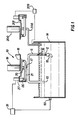
- the toner dispensing apparatus 10 comprises a generally U-shaped, tubular conduit 11 including an inlet opening 12 and an outlet opening 13.
- the openings 12, 13 are arranged to be submerged below the liquid level of a liquid developer composition reservoir 14.
- the reservoir 14 is of the type typically used in an electrophotographic copying machine to store a working dispersion, as is well known in the art.
- a pump 15 is operatively associated with the conduit 11 to circulate the liquid composition contained in the reservoir 14 through the conduit 11 via the inlet and outlet openings 12, 13 at a predetermined flow rate, as will be discussed in more detail below.
- a plurality of baffles 16 is arranged throughout the interior of the conduit 11 to impart a high shear, turbulent flow to the liquid composition as it is circulated through the conduit 11 by the pump 15.
- a toner inlet tube 17 is provided such that toner may be dispensed into the turbulent flow of liquid composition within the conduit 11.
- a toner cartridge clamp device 18 is arranged adjacent the inlet tube 17 to engage and support a pressurized toner cartridge 19 adjacent and in flow communication with the inlet tube 17.
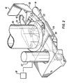
- the cartridge 19 is a can-type cartridge having a capacity of between 125-700 ml and using a driving gas such as freon 11, freon 12, butane, propane, nitrogen or dried air to drive the high concentration toner from the cartridge.
- the toner may occupy between 75-500 ml of the volume of the 125-700 ml capacity can.
- the cartridge may be made from aluminum and includes a pressure chamber 100, an expandable piston 101 and a toner solution storage area 102.
- a removable cap 103 is provided to permit the introduction of the driving gas under pressure into the pressure chamber 100.
- a valve element 20 is arranged at the discharge end of the cartridge 19 such that the valve element 20 is in flow communication with the inlet tube 17 when the cartridge is engaged and supported by the clamp device 18. The valve element 20 is activateable to displace an actuation rod 104 to release the pressurized gas from the pressure chamber 100 and into the piston 101.
- the valve element 20 is engageable by an activator lever 21 rotatably mounted on the clamp 18 for selective activation to discharge the pressurized toner.
- the activator lever 21 has a pair of angularly disposed arms 24 each of which is rotatably mounted upon an axle 22 which is supported between two downwardly extending flange members 23.
- the arms 24 are each integral with two side members 25, respectively.
- the side members 25 extend generally parallel to one another for a certain length, then converge toward one another and again extend in a parallel relation such that the two side members 25 are arranged closely adjacent a longitudinally movable actuator 26 of a solenoid 27.
- Each of the side members 25 includes a slot opening 28 adjacent the actuator 26 to receive a pin 29 extending through the actuator 26 whereby operation of the solenoid 27 displaces the actuator 26 longitudinally to thereby rotate the activator lever 21 about the axle 22.
- a platform-like member 30 is mounted between the side members 25 at a position directly below the valve element 20.
- the platform-like member 30 is formed to include an opening 21 to permit the positioning of the inlet tube 17 in fluid communication with the valve element 20 when the cartridge 19 is engaged and supported by the clamp device 18.
- the member 30 is also arranged to contact the valve element 20 upon rotation of the activator lever 21 about the axle 22 to provide the selective activation engagement between the activator lever 21 and the valve element 20.
- the solenoid 27 is electrically connected to an electrical control and power supply 31 for energization of the solenoid 27.
- the electrical control and power supply 31 may be operative in response to an optical sensor 50 as discussed above and as is known in the art.
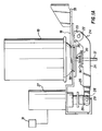
- the pressurized toner cartridge 19 is engaged and supported by a pair of opposed, rotatable clamp elements 32, 33, which are rotatably supported on the clamp device 18 at pivot points 34, 35, respectively.
- Each of the clamp elements 32, 33 includes a generally concave cartridge grip surface element 36, 37.
- the elements 36, 37 are arranged to grip the cartridge at the crimp 38 of the valve element 20 to the cartridge 19 upon rotation of each of the clamp elements 32, 33 toward the cartridge 19, as illustrated in Fig. 3.
- the crimp 38 is generally more uniform than the crimp of the top to the cartridge and therefore provides an advantageous gripping surface.
- the clamp elements 32, 33 include opposed spring supports 43, 44 to support a coil spring (not illustrated) and contacting, cooperating projections 45, 46 to facilitate the rotation of the clamp elements 32, 33 required to permit the insertion of the crimp 38 between the grip surfaces 36, 37 and the gripping engagement illustrated in Fig. 3. Moreover, stops 47, 48, are provided, to limit the pivoting movement by the clamp elements 32, 33.
- An opening 39 is formed in the clamp device 18 and positioned between the grip surface elements 36, 37. Accordingly, a pressurized cartridge 19 containing toner may be inserted through the opening 39 such that the valve element 20 is placed in flow communication with the inlet tube 17.
- the clamp elements 32, 33 are then rotated to bring the grip surfaces 36, 37 into engagement with the crimp 38.
- the clamp element 33 is provided with an upwardly extending flange 40 to rotatably support a locking member 41.
- the locking member 41 is rotatable into engagement with a seat portion 42 formed on the clamp element 32 to hold the clamp elements 32, 33 in the crimp 38 engaging position and thereby support the cartridge 19 on the toner dispensing apparatus 10.
- engerization of the solenoid 27 by the power supply 31 is coordinated with the activation of the pump 15 such that the turbulent liquid flow through the conduit 11 commences prior to the engerization of the solenoid 27.
- the activation of the pump 15 and engerization of the solenoid 27 may be controlled by a monitoring means including an optical sensor 50, as is well known in the art.
- the actuator 26 is displaced longitudinally upward to rotate the activator lever 21 about the axle 22 via the pin 29-slot 28 connection into activating engagement with the valve element 20.
- the high concentration viscous toner is discharged due to gas pressure activation of the piston 101 from the cartridge 19 through the valve element 20 and into the inlet tube 17.
- the pressure discharged, high concentration toner will then enter the conduit 11 from the inlet tube 17 to mix with the turbulent, high shear flow of liquid composition as explained above.
- the conduit is approximately one foot in length and a half inch in diameter.
- the pump 15 is operated to provide a 6 1/min flow rate of liquid composition through the conduit 11.
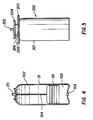
- a second pressure cartridge comprises an aerosol can 200 containing a supply of charge director dispersed in a suitable aerosol propellant.
- the can 200 is mounted in a clamp device 201 which is generally of the same construction as the clamp device 18 used to mount the toner cartridge 19.
- the can 200 is a conventional aerosol can including a discharge valve 202 and crimps 203, 204 to fasten the top 205 and valve support 206 respectively to the cylindrical body 207 of the can 200.
- the clamp device 200 is arranged to grip the crimp 204 such that the can 200 is securely mounted in the device 201.
- the discharge valve 202 is in fluid communication with a tube 208 which extends from the valve 202 to the liquid developer composition reservoir 14.
- the clamp device 201 is operative to selectively activate the discharge valve 202 for a precise, preselected period of time such that a predetermined amount of charge director, e.g. 40 microliters, or more is dispensed to the reservoir 14, when and as desired.
- the clamp drive 201 is selectively activated by a conductivity sensor and electrical controller 209 which monitors the conductivity of the working dispersion to determine when charge director is to be added to the reservoir.
- the high concentration toner solution of the present invention comprises greater than 15% toner solids and preferably between 20% and 30% toner solids.
- the concentrated toner solution can be initially formed using otherwise conventional methods which are modified only as is necessary to increase the percentage of solids. Alternatively, a typical 10% solids toner solution can be filtered, e.g. on a polypropylene cloth, until the desired solids concentration is achieved.
- viscosity of the toner solution will increase as the percentage of solids is increased.
- the actual viscosity of the solution will be dependent on several factors such as the specific percentage of solids, the temperature of the solution and the pigment-to-resin ratio .
- a typical toner concentrate of the present invention having about 27% solids has been found to have a viscosity of about 40,000-50,000 centipoise at room temperature.
- dispensing apparatus described above has been found to be especially suitable for dispensing the concentrated toner solution described herein, it will be appreciated that other forms of dispensers which are capable of dispensing viscous fluids may also be employed.
- the invention provides a highly effective means to dispense accurate amounts of an advantageous high concentration toner to a working dispersion.
- the pressurized discharge is effective in efficiently dispensing a viscous toner supply and the turbulent working dispersion flow assures a thorough mixing of the dispensed high concentration toner with the working dispersion.
- the basic teaching of the invention is also advantageously applicable to a means to accurately dispense very small quantities of charge director to the liquid developer reservoir.
Applications Claiming Priority (2)
| Application Number | Priority Date | Filing Date | Title |
|---|---|---|---|
| US9145487A | 1987-08-31 | 1987-08-31 | |
| US91454 | 1987-08-31 |
Publications (2)
| Publication Number | Publication Date |
|---|---|
| EP0306217A2 true EP0306217A2 (fr) | 1989-03-08 |
| EP0306217A3 EP0306217A3 (fr) | 1989-08-23 |
Family
ID=22227871
Family Applications (1)
| Application Number | Title | Priority Date | Filing Date |
|---|---|---|---|
| EP88307884A Withdrawn EP0306217A3 (fr) | 1987-08-31 | 1988-08-25 | Mécanisme de distribution d'une solution de toner concentré et de toner sous pession |
Country Status (3)
| Country | Link |
|---|---|
| EP (1) | EP0306217A3 (fr) |
| JP (1) | JPH01140180A (fr) |
| KR (1) | KR890004215A (fr) |
Cited By (14)
| Publication number | Priority date | Publication date | Assignee | Title |
|---|---|---|---|---|
| US4994860A (en) * | 1990-04-10 | 1991-02-19 | Minnesota Mining And Manufacturing | Liquid toners handling network for an electrographic printer |
| US5003352A (en) * | 1989-10-24 | 1991-03-26 | Am International, Inc. | Liquid toner supply system and method |
| DE4102889A1 (de) * | 1990-01-31 | 1991-08-01 | Ricoh Kk | Fluessigentwickler-zufuehrvorrichtung fuer eine entwicklungseinheit |
| WO1992017824A1 (fr) * | 1991-03-26 | 1992-10-15 | Spectrum Sciences B.V. | Distributeur de toner liquide |
| EP0695977A1 (fr) * | 1994-08-03 | 1996-02-07 | Hewlett-Packard Company | Cartouche pour concentrat de toner |
| US5596396A (en) * | 1991-07-09 | 1997-01-21 | Indigo N.V. | Latent image development apparatus |
| WO1997012289A1 (fr) * | 1995-09-26 | 1997-04-03 | Minnesota Mining And Manufacturing Company | Procede et dispositif pour appliquer un toner liquide a un support d'impression |
| US5655194A (en) * | 1991-03-26 | 1997-08-05 | Indigo N.V. | Dispenser apparatus especially for liquid toner concentrate |
| US5970273A (en) * | 1998-07-07 | 1999-10-19 | Imation Corp. | Ink cartridge for liquid electrographic imaging devices |
| US6088560A (en) * | 1998-07-07 | 2000-07-11 | Imation Corp. | Liquid ink replenishment system for liquid electrographic imaging devices |
| USRE37859E1 (en) | 1991-07-09 | 2002-09-24 | Indigo N.V. | Development control system |
| WO2006086041A2 (fr) * | 2004-12-22 | 2006-08-17 | The Boeing Company | Dispositif de surveillance de melangeage de colles |
| WO2020046343A1 (fr) * | 2018-08-30 | 2020-03-05 | Hewlett-Packard Development Company, L.P. | Dispositif de remplissage de particules d'impression |
| CN111033389A (zh) * | 2017-09-06 | 2020-04-17 | 惠普印迪格公司 | 墨配料 |
Citations (6)
| Publication number | Priority date | Publication date | Assignee | Title |
|---|---|---|---|---|
| GB1253554A (en) * | 1969-02-14 | 1971-11-17 | Ricoh Kk | Improvements in and relating to electrophotographic copying apparatus |
| US3651782A (en) * | 1969-09-02 | 1972-03-28 | Eastman Kodak Co | Liquid development apparatus |
| US3749289A (en) * | 1971-07-06 | 1973-07-31 | Varian Associates | Liquid toner concentrate dispenser for an electrophotographic developing system |
| US3789794A (en) * | 1971-12-27 | 1974-02-05 | Savin Business Machines Corp | Apparatus for developing electrostatic images |
| US3862849A (en) * | 1967-12-05 | 1975-01-28 | Ricoh Kk | Method for preparation of developing solution for developing electrostatic latent images |
| WO1987005128A1 (fr) * | 1986-02-14 | 1987-08-27 | Savin Corporation | Regulation du repartiteur de charge dans un revelateur liquide |
-
1988
- 1988-08-25 EP EP88307884A patent/EP0306217A3/fr not_active Withdrawn
- 1988-08-29 JP JP63214738A patent/JPH01140180A/ja active Pending
- 1988-08-30 KR KR1019880011073A patent/KR890004215A/ko not_active Application Discontinuation
Patent Citations (6)
| Publication number | Priority date | Publication date | Assignee | Title |
|---|---|---|---|---|
| US3862849A (en) * | 1967-12-05 | 1975-01-28 | Ricoh Kk | Method for preparation of developing solution for developing electrostatic latent images |
| GB1253554A (en) * | 1969-02-14 | 1971-11-17 | Ricoh Kk | Improvements in and relating to electrophotographic copying apparatus |
| US3651782A (en) * | 1969-09-02 | 1972-03-28 | Eastman Kodak Co | Liquid development apparatus |
| US3749289A (en) * | 1971-07-06 | 1973-07-31 | Varian Associates | Liquid toner concentrate dispenser for an electrophotographic developing system |
| US3789794A (en) * | 1971-12-27 | 1974-02-05 | Savin Business Machines Corp | Apparatus for developing electrostatic images |
| WO1987005128A1 (fr) * | 1986-02-14 | 1987-08-27 | Savin Corporation | Regulation du repartiteur de charge dans un revelateur liquide |
Cited By (21)
| Publication number | Priority date | Publication date | Assignee | Title |
|---|---|---|---|---|
| US5003352A (en) * | 1989-10-24 | 1991-03-26 | Am International, Inc. | Liquid toner supply system and method |
| EP0425144A2 (fr) * | 1989-10-24 | 1991-05-02 | Am International Incorporated | Méthode et système d'alimentation en toner liquide |
| EP0425144A3 (en) * | 1989-10-24 | 1992-08-12 | Am International, Inc | Liquid toner supply system and method |
| DE4102889A1 (de) * | 1990-01-31 | 1991-08-01 | Ricoh Kk | Fluessigentwickler-zufuehrvorrichtung fuer eine entwicklungseinheit |
| US4994860A (en) * | 1990-04-10 | 1991-02-19 | Minnesota Mining And Manufacturing | Liquid toners handling network for an electrographic printer |
| US6155457A (en) * | 1991-03-26 | 2000-12-05 | Indigo N.V. | Dispenser apparatus especially for liquid toner concentrate |
| WO1992017824A1 (fr) * | 1991-03-26 | 1992-10-15 | Spectrum Sciences B.V. | Distributeur de toner liquide |
| US5655194A (en) * | 1991-03-26 | 1997-08-05 | Indigo N.V. | Dispenser apparatus especially for liquid toner concentrate |
| US5596396A (en) * | 1991-07-09 | 1997-01-21 | Indigo N.V. | Latent image development apparatus |
| USRE37859E1 (en) | 1991-07-09 | 2002-09-24 | Indigo N.V. | Development control system |
| EP0695977A1 (fr) * | 1994-08-03 | 1996-02-07 | Hewlett-Packard Company | Cartouche pour concentrat de toner |
| US5701561A (en) * | 1995-09-26 | 1997-12-23 | Minnesota Mining And Manufacturing Company | Method and apparatus for applying liquid toner to a print medium using multiple toner applicators for each liquid toner |
| WO1997012289A1 (fr) * | 1995-09-26 | 1997-04-03 | Minnesota Mining And Manufacturing Company | Procede et dispositif pour appliquer un toner liquide a un support d'impression |
| US6088560A (en) * | 1998-07-07 | 2000-07-11 | Imation Corp. | Liquid ink replenishment system for liquid electrographic imaging devices |
| US5970273A (en) * | 1998-07-07 | 1999-10-19 | Imation Corp. | Ink cartridge for liquid electrographic imaging devices |
| WO2006086041A2 (fr) * | 2004-12-22 | 2006-08-17 | The Boeing Company | Dispositif de surveillance de melangeage de colles |
| WO2006086041A3 (fr) * | 2004-12-22 | 2006-09-14 | Boeing Co | Dispositif de surveillance de melangeage de colles |
| CN111033389A (zh) * | 2017-09-06 | 2020-04-17 | 惠普印迪格公司 | 墨配料 |
| CN111033389B (zh) * | 2017-09-06 | 2022-07-08 | 惠普印迪格公司 | 用于将墨精确配料到墨盒中的系统、方法以及存储器资源 |
| WO2020046343A1 (fr) * | 2018-08-30 | 2020-03-05 | Hewlett-Packard Development Company, L.P. | Dispositif de remplissage de particules d'impression |
| US11613126B2 (en) | 2018-08-30 | 2023-03-28 | Hewlett-Packard Development Company, L.P. | Print particle replenishment device |
Also Published As
| Publication number | Publication date |
|---|---|
| JPH01140180A (ja) | 1989-06-01 |
| KR890004215A (ko) | 1989-04-20 |
| EP0306217A3 (fr) | 1989-08-23 |
Similar Documents
| Publication | Publication Date | Title |
|---|---|---|
| EP0306217A2 (fr) | Mécanisme de distribution d'une solution de toner concentré et de toner sous pession | |
| US3902635A (en) | Fluid dispensing apparatus | |
| US5050798A (en) | Static air freshener device and cartridge | |
| EP0810091B1 (fr) | Système d'alimentation en encre pour un dispositif d'impression | |
| JP4021012B2 (ja) | 印刷システム及びその動作方法 | |
| JPH06508932A (ja) | 分配装置 | |
| DE19929009A1 (de) | Entwicklerbehälter für einen Bilderzeugungsapparat und Verfahren zum Fördern eines Entwicklers | |
| JPH10235891A (ja) | インクジェット・プリンタ用インク補給装置 | |
| DE3611790A1 (de) | Vorrichtung zur erzeugung einer abbildung | |
| US4289092A (en) | Liquid development fountain | |
| DE102007037916A1 (de) | Verfahren zur Herstellung eines Flüssigkeitsbehälters und Flüssigkeitsbehälter | |
| RU2397526C2 (ru) | Устройство для формирования изображения и способ его управления | |
| US3709198A (en) | Liquid heater and storage means | |
| US4785327A (en) | Pneumatic charge director dispensing apparatus | |
| US5530533A (en) | High solids toner redispersion | |
| US4994862A (en) | Fusing station having release oil application cartridge | |
| EP1457344A1 (fr) | Système d'impression à densité constante | |
| US5438921A (en) | Stencil printing device having an ink mixing unit | |
| EP0416494B1 (fr) | Dispositif de développement par voie liquide et réservoir de stockage utilisé par ce dispositif | |
| JPS58171997A (ja) | 使い捨てインク・マ−カ−およびその製造方法 | |
| DE60015905T2 (de) | Verfahren zur Steuerung eines Tintenrührers für einen elektrophotographischen Drucker mit Nassentwicklung | |
| US6810226B2 (en) | Electrophotographic toner containment apparatus and methods | |
| EP0312080B1 (fr) | Appareil automatique portable pour carbonater l'eau ne nécessitant par d'appareillage électrique | |
| KR102098465B1 (ko) | 농도유지유닛 및 이를 포함하는 전착도장장치 | |
| US5690438A (en) | Continuous or endless loop printing ribbon cassettes and reinking devices therefor |
Legal Events
| Date | Code | Title | Description |
|---|---|---|---|
| PUAI | Public reference made under article 153(3) epc to a published international application that has entered the european phase |
Free format text: ORIGINAL CODE: 0009012 |
|
| AK | Designated contracting states |
Kind code of ref document: A2 Designated state(s): CH DE FR GB IT LI |
|
| PUAL | Search report despatched |
Free format text: ORIGINAL CODE: 0009013 |
|
| AK | Designated contracting states |
Kind code of ref document: A3 Designated state(s): CH DE FR GB IT LI |
|
| 17P | Request for examination filed |
Effective date: 19900130 |
|
| STAA | Information on the status of an ep patent application or granted ep patent |
Free format text: STATUS: THE APPLICATION HAS BEEN WITHDRAWN |
|
| 18W | Application withdrawn |
Withdrawal date: 19910619 |