EP0305945A2 - Hydrostatische Dichtungseinrichtung für Reaktorkühlpumpe mit von aussen unter Druck gesetzter hydraulischer Ausgleichsammer - Google Patents
Hydrostatische Dichtungseinrichtung für Reaktorkühlpumpe mit von aussen unter Druck gesetzter hydraulischer Ausgleichsammer Download PDFInfo
- Publication number
- EP0305945A2 EP0305945A2 EP88114047A EP88114047A EP0305945A2 EP 0305945 A2 EP0305945 A2 EP 0305945A2 EP 88114047 A EP88114047 A EP 88114047A EP 88114047 A EP88114047 A EP 88114047A EP 0305945 A2 EP0305945 A2 EP 0305945A2
- Authority
- EP
- European Patent Office
- Prior art keywords
- seal ring
- fluid
- sealing assembly
- pressure
- balance
- Prior art date
- Legal status (The legal status is an assumption and is not a legal conclusion. Google has not performed a legal analysis and makes no representation as to the accuracy of the status listed.)
- Granted
Links
Images


Classifications
-
- F—MECHANICAL ENGINEERING; LIGHTING; HEATING; WEAPONS; BLASTING
- F04—POSITIVE - DISPLACEMENT MACHINES FOR LIQUIDS; PUMPS FOR LIQUIDS OR ELASTIC FLUIDS
- F04D—NON-POSITIVE-DISPLACEMENT PUMPS
- F04D29/00—Details, component parts, or accessories
- F04D29/08—Sealings
- F04D29/10—Shaft sealings
- F04D29/12—Shaft sealings using sealing-rings
- F04D29/126—Shaft sealings using sealing-rings especially adapted for liquid pumps
- F04D29/128—Shaft sealings using sealing-rings especially adapted for liquid pumps with special means for adducting cooling or sealing fluid
-
- F—MECHANICAL ENGINEERING; LIGHTING; HEATING; WEAPONS; BLASTING
- F04—POSITIVE - DISPLACEMENT MACHINES FOR LIQUIDS; PUMPS FOR LIQUIDS OR ELASTIC FLUIDS
- F04D—NON-POSITIVE-DISPLACEMENT PUMPS
- F04D7/00—Pumps adapted for handling specific fluids, e.g. by selection of specific materials for pumps or pump parts
- F04D7/02—Pumps adapted for handling specific fluids, e.g. by selection of specific materials for pumps or pump parts of centrifugal type
- F04D7/06—Pumps adapted for handling specific fluids, e.g. by selection of specific materials for pumps or pump parts of centrifugal type the fluids being hot or corrosive, e.g. liquid metals
-
- F—MECHANICAL ENGINEERING; LIGHTING; HEATING; WEAPONS; BLASTING
- F16—ENGINEERING ELEMENTS AND UNITS; GENERAL MEASURES FOR PRODUCING AND MAINTAINING EFFECTIVE FUNCTIONING OF MACHINES OR INSTALLATIONS; THERMAL INSULATION IN GENERAL
- F16J—PISTONS; CYLINDERS; SEALINGS
- F16J15/00—Sealings
- F16J15/16—Sealings between relatively-moving surfaces
- F16J15/34—Sealings between relatively-moving surfaces with slip-ring pressed against a more or less radial face on one member
- F16J15/3436—Pressing means
- F16J15/346—Pressing means the pressing force varying during operation
-
- Y—GENERAL TAGGING OF NEW TECHNOLOGICAL DEVELOPMENTS; GENERAL TAGGING OF CROSS-SECTIONAL TECHNOLOGIES SPANNING OVER SEVERAL SECTIONS OF THE IPC; TECHNICAL SUBJECTS COVERED BY FORMER USPC CROSS-REFERENCE ART COLLECTIONS [XRACs] AND DIGESTS
- Y10—TECHNICAL SUBJECTS COVERED BY FORMER USPC
- Y10S—TECHNICAL SUBJECTS COVERED BY FORMER USPC CROSS-REFERENCE ART COLLECTIONS [XRACs] AND DIGESTS
- Y10S277/00—Seal for a joint or juncture
- Y10S277/929—Seal feature where change in operation or condition induces additional leakage control
Definitions
- the present invention relates generally to shaft seals and, more particularly, is concerned with a hydrostatic sealing assembly with an externally pressurized hydraulic balance chamber for sealing a shaft of a reactor coolant pump used in a nuclear power plant.
- a reactor coolant system In pressurized water nuclear power plants, a reactor coolant system is used to transport heat from the reactor core to steam generators for the production of steam. The steam is then used to drive a turbine generator.
- the reactor coolant system includes a plurality of separate cooling loops, each connected to the reactor core and containing a steam generator and a reactor coolant pump.
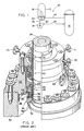
- the reactor coolant pump typically is a vertical, single stage, centrifugal pump designed to move large volumes of reactor coolant at high temperatures and pressures.
- the pump basically includes three general sections from bottom to top -- hydraulic, shaft seal and motor sections.
- the lower hydraulic section includes an impeller mounted on the lower end of a pump shaft which is operable within the pump casing to pump reactor coolant about the respective loop.
- the upper motor section includes a motor which is coupled to drive the pump shaft.
- the middle shaft seal section includes three tandem sealing assemblies -lower primary, middle secondary and upper tertiary sealing assemblies. The sealing assemblies are located concentric to, and near the top end of, the pump shaft and their combined purpose is to provide for zero reactor coolant leakage along the pump shaft to the containment atmosphere during normal operating condition.
- the lower primary sealing assembly is the main seal of the pump. It is typically a hydrostatic, radially tapered "film-riding", controlled leakage seal whose primary components are an annular runner which rotates with the pump shaft and a non-rotating seal ring which is attached to the housing of the lower sealing assembly.
- hydrostatic seals are the one disclosed hereinbelow, and the ones disclosed in the MacCrum, Singleton, Villasor and Andrews et al. patents.
- the pump shaft seals constitute the main problem area for the rector coolant pumps and significantly contribute to the utilization factor in nuclear power plants.
- the seals must be capable of breaking down the high system pressure (about 17.2 MPa (2500 psi)) safely.
- the tandem arrangement of three seals is used to break down the pressure
- the lower main seal absorbs most of the pressure drop (approximately 15.5 MPa (2500 psi)).
- the lower seal Being a hydrostatic "film-riding" seal, the lower seal is designed to "lift off” (separate) at low system pressures without pump rotation.
- the lifting force is produced by a hydrostatic pressure force present in the gap between the stationary seal ring and the rotating runner.
- a closing or seating force which must balance the lifting force, is produced by the system pressure acting on the surfaces opposite the film surfaces of the seal ring and runner.
- One of the potential problems associated with the lower seal stems from the preference to use a very pure grade of aluminum oxide as the faceplate material for the seal ring and runner.
- Use of such material is advantageous since it is harder than crud particles (usually iron oxide) which are small enough to enter the gap between the faces of the seal ring and runner, but large enough to lodge part way through the gap.
- crud particles usually iron oxide
- a major disadvantage of aluminum oxide is that it is basically incompatible in rubbing against itself. If the seal faces momentarily contact while in motion, then usually some damage can be expected. If the rub is heavy enough, the faces are very seriously damaged and in some cases the thermal shock can lead to cracking and breakup of the structure.
- a minimum differential pressure of about 1.37 MPa (200 psi) must be maintained to establish a stable film between the faces and prevent rubbing when starting the pump.
- a minimum leakrate of about 0.75 liter per minute (0.2 gpm) is required for cooling and, most importantly, as a means of determining that an adequate film thickness exists prior to starting.
- the seal is most vulnerable at plant startup since the available differential pressure is low and crud may be present. Once the film is established, however, there is practically no seal face wear and the seal has a very long life expectancy.
- a pump having a shaft and a housing having an exterior and an interior for containing pressurized system fluid, an external system fluid source for providing pressurized system fluid to said housing interior at a supply pressure which is variable between a low pressure at pump startup and a high pressure at pump operation, and a hydrostatic sealing assembly for sealably and rotatably mounting said shaft within said housing interior, said sealing assembly characterized by: (a) an annular runner circumscribing and mounted around said shaft for rotation therewith; (b) an annular seal ring circumscribing and mounted within said housing interior in non-rotational relationship thereto but for translatory movement along said shaft and said housing; (c) said runner and seal ring having surfaces facing one another and between which pressurized system fluid within said housing interior creates a flowing film of low pressure fluid which prevents said facing surfaces of said respective runner and seal ring from coming into contact with one another so long as a predetermined minimum leakrate is maintained therebetween; (d)
- first surface of the seal ring defines a substantially larger area than the second surface thereof.
- means defining the first and second surfaces on the seal ring includes first and second spaced apart annular seal means disposed along the seal ring between the seal ring and the shaft, and defining first and second chambers disposed contiguous with the first and second isolated surfaces on the seal ring.
- the balance fluid flow communication providing means is a flow passage defined within the housing from the exterior thereof to the second chamber disposed contiguous with the second surface of the seal ring.
- the external system fluid source includes a pressurized fluid pumping source and a main fluid flow line connecting the pumping source to the housing interior to communicate pressurized system fluid thereto.
- the external balance fluid source includes a bypass fluid flow means connecting the main fluid flow line to the balance fluid flow passage and a differential pressure regulating valve disposed in the bypass fluid flow means for receiving pressurized system fluid and producing the pressurized balance fluid.
- the sealing assembly of the present invention relates to a hydrostatic seal with an externally pressurized balance chamber.
- the chamber is connected to an external pressure source which regulates the seating force of a seal ring by either increasing or reducing the axial hydrostatic load on the seal ring.
- This feature will extend the hydrostatic operating range of the sealing assembly to very low pressures by reducing the seating force sufficiently to balance the hydraulic lift forces developed in the hydrostatic facing surfaces on the runner and seal ring of the sealing assembly.
- This is particularly useful in reactor coolant pump shaft seal systems which require relatively high leakrates at low (pump startup) supply pressures and low leakrates at high (pump operating) supply pressures.
- the cooling loop 10 includes a steam generator 12 and a reactor coolant pump 14 serially connected in a closed coolant flow circuit with a nuclear reactor core 16.
- the steam generator 12 includes primary tubes 18 communicating with inlet and outlet plenums 20, 22 of the generator 12.
- the inlet plenum 20 of the steam generator 12 is connected in flow communication with the outlet of the reactor core 16 for receiving hot coolant therefrom along flow path 24 of the closed flow circuit.
- the outlet plenum 22 of the steam generator 12 is connected in flow communication with an inlet suction side of the reactor coolant pump 14 along flow path 26 of the closed flow circuit.
- the outlet pressure side of the reactor coolant pump 14 is connected in flow communication with the inlet of the reactor core 16 for feeding cold coolant thereto along flow path 28 of the closed flow circuit.
- the coolant pump 14 pumps the coolant under high pressure about the closed flow circuit.
- hot coolant emanating from the reactor core 16 is conducted to the inlet plenum 20 of the steam generator 12 and to the primary tubes 18 in communication therewith. While in the primary tubes 18, the hot coolant flows in heat exchange relationship with cool feedwater supplied to the steam generator 12 via conventional means (not shown).
- the feedwater is heated and portions thereof changed to steam for use in driving a turbine generator (not shown).
- the coolant whose temperature has been reduced by the heat exchange, is then recirculated to the reactor core 16 via the coolant pump 14.
- the reactor coolant pump 14 must be capable of moving large volumes of reactor coolant at high temperatures and pressures about the closed flow circuit. Although the temperature of the coolant flowing from the steam generator 12 to the pump 14 after heat exchange has been cooled substantially below the temperature of the coolant flowing to the st®am generator 12 from the reactor core 16 before heat exchange, its temperature is still relatively high, being typically about 288 degrees C (550 degrees F). The coolant pressure sealed by the pump is typically about 15.5 MPa (2250 psi).
- the prior art reactor coolant pump 14 generally includes a pump housing 30 which terminates at one end in a seal housing 32.
- the pump 14 also includes a pump shaft 34 extending centrally of the housing 30 and being sealingly and rotatably mounted within the seal housing 32.
- the bottom portion of the pump shaft 34 is connected to an impeller, while a top portion thereof is connected to a high-horsepower, induction-type electric motor.
- the impeller within the interior 36 of the housing 30 circulates the coolant flowing through the pump housing 30 at pressures from ambient to approximately 17.2 MPa (2500 psi).
- This pressurized coolant applies an upwardly directed, hydrostatic load upon the shaft 34 since the outer portion of the seal housing 32 is surrounded by the ambient atmosphere.
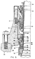
- tandemly-arranged lower primary, middle secondary and upper tertiary sealing assemblies 38, 40, 42 are provided in the positions illustrated in Figs. 2 and 3 about the pump shaft 34 and within the pump housing 30.
- the lower primary sealing assembly 38 which performs most of the pressure sealing is of the non-contacting hydrostatic type, whereas the middle secondary and upper tertiary sealing assemblies 40, 42 are of the contacting, mechanical type.
- the lower hydrostatic primary sealing assembly 38 of the prior art pump 14 generally includes an annular runner 44 which is mounted to the pump shaft 34 for rotation therewith and an annular seal ring 46 which is stationarily mounted within the seal housing 32.
- the runner 44 includes an annular runner faceplate 48 mounted by a hydrostatic clamp ring 50 to an annular runner support member 52 which, in turn, is keyed to the pump shaft 34 by anti-rotation pins 54.
- the seal ring 46 includes an annular ring faceplate 56 mounted by a hydrostatic clamp ring 58 to an annular ring support member 60 which, in turn, is keyed to the seal housing 32 by anti-rotation pin 62 so as to prevent rotational movement of the seal ring 46 relative to the seal housing 32 but allow translatory movement of the seal ring 46 along pump shaft 34 toward and away from the runner 44.
- Facing (or top and bottom) surfaces 64, 66 of the respective runner and ring faceplates 48, 56 are biased toward one another as a result of the coolant pressure load on the pump shaft 34.
- the surfaces 64, 66 normally do not frictionally engage one another, since the surface 66 of the seal ring faceplate 56 is tapered at a shallow angle with respect to the substantially flat and horizontal surface 64 on the runner faceplate 48.
- Such tapering provides a flowing film of coolant fluid between the surfaces 64, 66 which, in turn, allows the runner 44 and seal ring 46 to rotate relative to one another in a "film-riding" mode.
- the seal housing 32 includes a primary leakoff port 68, whereas leakoff port 70 accommodates coolant fluid leakoff from the secondary sealing assembly 40 and leakoff port 71 accommodates coolant fluid leakoff from the tertiary sealing assembly 42.
- the facing surfaces 64, 66 of the respective runner 44 and seal ring 46 of the primary sealing assembly 38 are designed to "lift-off" or separate at low system pressure without pump shaft rotation.
- the lifting force is produced by the hydrostatic pressure force between the runner 44 and seal ring 46.
- an opposing seating force which must balance the lifting force, is produced by the system pressure acting on a pair of adjacent outer and inner peripheral upwardly-facing surfaces 72, 74 of the seal ring 46 located on an opposite side thereof from its downwardly-facing surface 66.
- the lifting force graphically depicted in Fig. 10, varies inversely with film thickness between the facing surfaces 64, 66 of the runner 44 and seal ring 46. So where the ring 46 is tapered with a convergent flow path, the lifting force will decrease as the film thickness increases.
- the seal provided by the O-ring 76 not only prevents leakage, but also serves to determine the magnitude of the seating force.
- the O-ring 76 defines an upper chamber 81 which communicates with system pressure fluid and a lower chamber 83 which communicates with low pressure fluid emanating from the flow of fluid film into the gap between the facing surfaces 64, 66.
- the inner diameter of the upper portion of seal ring 46 determines the position of transition from high system pressure to low back pressure and thus determines the magnitude of the pressure component of the seating force in Fig. 10.
- the seating force is quite sizable. At full system pressure, it is nearly equal to 445 kN (100,000 lbs.).
- the material of the faceplates 48, 56 in Fig. 4 is preferably aluminum oxide.
- a minimum differential pressure approximately 1.37 MPa (200 psi)
- the seal provided between the faceplates is most vulnerable at startup since the available differential pressure is low and the sealing film must be established to prevent rubbing of the facing surfaces 64, 66.
- the resulting leakage is an order of magnitude less than at full pressure.
- the required minimum leakage to startup of about 0.75 liter per minute (0.2 gpm) can, in fact, be too small to accurately measure with the instruments that are presently used in reactor power plants.
- low leakage can be an indication of possible crud blockage at the facing surfaces 64, 66 or failure of the surfaces to separate, operators are reluctant to start the pump to avoid damaging the facing surfaces of the primary sealing assembly 38. In a high percentage of cases, the low leakrates are simply due to unreliable instrumentation. To correct the problem or confirm the lack of a problem operators conduct a number of involved system checks. The effort is a time consuming and a continuing nuisance in an operation where the pumps represent a small part of the startup logistics.
- seal designers can open up the seal faceplate convergence angle (taper). However, as can be understood from the graph of Fig. 11, this would result in high leakrates across the entire pressure range.
- the primary disadvantage with this technique is at high system pressure where the resulting leakrates approach and may exceed shutdown limits.
- the increased convergence angle (taper) is, in fact, opposite to what seal designers would prefer to introduce were it not for the low pressure leakage requirement.
- a reduction in the convergence angle (taper) would reduce the high pressure leakrates and provide significantly more margin to shutdown limits, but this would introduce leakrates below the minimum acceptable at low system pressures (i.e., 0.75 liter per minute at 1.37 MPa (0.2 gpm at 200 psig)).
- the solution to the problem is a seal which maintains a constant leakage over the pressure range.
- either the convergence angle (taper) or seating force would have to change in a controlled manner over the entire system pressure range. Varying either one of these parameters in a controlled fashion becomes a very difficult and complex challenge.
- a more practical and relatively simple alternative is proposed by the present invention.
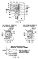
- Figs. 5-7 and 12 there is shown the modified primary sealing assembly of the present invention, being generally designated by the numeral 82. Only the parts of the modified primary sealing assembly 82 which are different from the prior art primary sealing assembly 38 (best seen in Fig. 4), and thus relate to the modifications underlying the present invention, will be described in detail hereafter and be identified by different reference numerals.
- the modified primary sealing assembly 82 includes a modified seal ring 84 having first, second and third annular peripheral upper surfaces 86, 88, 90.
- the first and third peripheral surfaces 86, 90 face in a direction opposite to that faced by the second peripheral surface 88 and the same as that faced by the bottom surface 92 of the seal ring 84 which faces the adjacent top surface 64 of the faceplate 48 of the runner 44.
- the respective peripheral upper surfaces 86, 88, 90 are sealingly isolated from one another by first and second annular seal means in the form of a pair of grooves 94, 96 and a pair of O-rings 102, 104 disposed in the respective pair of grooves 94, 96.
- Vertical surfaces 98, 100 located at the inside diameter of the seal ring 84 extend transversely between and interconnect the respective peripheral surfaces 86, 88, 90, as seen in Figs. 6 and 12.
- the groove 94 is defined in the upper inner vertical surface 98 on the seal ring 84, whereas the groove 96 is defined in the lower vertical surface 101 of the seal housing 32.
- the one upper groove 94 and associated O-ring 102 which comprise the first or upper annular seal means are disposed along the seal ring 84 between it and the shaft 34 and between the first and second peripheral upper surfaces 86, 88 thereon.
- a first or upper balance chamber 106 is defined contiguous with the first peripheral surface 86 which communicates with the pressurized system fluid in the housing 30 at the supply pressure thereof.
- the other lower groove 96 and associated O-ring 104 which comprise the second or lower annular seal means are likewise disposed along the seal ring 84 between it and the shaft 34, but between the second and third peripheral upper surfaces 88, 90 thereon.
- a second or middle balance chamber 108 is defined contiguous with the second peripheral surface 88
- a third or lower balance chamber 110 is defined contiguous with the third peripheral surface 90 which communicates with the fluid film that flows between the facing surfaces 64, 92 of the runner 44 and seal ring 84 at the low pressure thereof.
- the first, second and third balance chambers 106, 108, 110 are defined by the first and second annular seal means in substantially noncommunicative isolated relationship to one another. It will be observed that the first balance surface 86 covers a substantially larger area than either the second or third surfaces 88, 90. In view of the larger area of the first surface 86 compared to the third surface 90, it can be understood that a large proportion of the seating force will be produced at the first surface 86 in response to the supply pressure of the pressurized system fluid in the housing 30.
- an external system fluid source 112 in the form of a conventional existing injection system is connected to the pump housing 30 to provide pressurized system fluid to the housing interior 36 at the supply pressure.
- the supply pressure is variable between a low pressure at pump startup and a high pressure at pump operation.
- the external system fluid source 112 includes a pressurized fluid pumping source in the form of a charging pump 114 and a main fluid flow line 116 connecting the charging pump 114 to the housing interior 36 via an injection supply port (not shown) being similar to port 73 on the prior art pump housing 30 of Figure 2 to communicate pressurized system fluid thereto.
- the referred to injection system is an existing part of the present pump seal injection system which in essence has been simply modified to take a feed off for the balance chamber pressure regulation.
- an external balance fluid source 118 is connected to the pump housing 30, or more specifically to the portion thereof called the seal housing 32, for providing pressurized balance fluid to the second chamber 108 and the second surface 88 on the seal ring 84 being contiguous therewith.
- Means for providing flow communication of pressurized balance fluid from the external balance fluid source 118 to the second chamber 108 and the second seal ring surface 88 is in the form of a flow passage 120 (Figs. 5 and 6) defined within the housing 32 from the exterior thereof to the second chamber 108.
- the flow passage 120 is sealed by O-ring seals 121 in the housing 32.
- the external balance fluid source 118 can take any one of many different suitable forms which can provide a pressurized balance fluid to the second chamber 108 at a balance pressure being greater than the supply pressure of the pressurized system fluid (communicated to the first chamber 106) by a differential pressure having a constant proportional relationship to the supply pressure.
- such balance pressure of the fluid in the second chamber 108 is effective at pump startup, when the supply pressure of the fluid in the housing 30 and first chamber 106 is low, to apply a lifting force on the seal ring second surface 88 which augments a lifting force imposed on the seal ring bottom facing surface 92 by the supply pressure in countering a seating force imposed on the ring first surface 86 by the supply pressure.
- the seating force is sufficiently overcome at the low system pressure so that at pump startup the hydrostatic lifting force between the facing surfaces 64, 92 of the runner 44 and seal ring 84 is sufficient to support a film and produce a leakrate therebetween which is above the predetermined minimum necessary to keep the surface from contacting one another.
- balance pressure of the fluid in the second chamber l08 is ineffective at full pump operation when the supply pressure of the system fluid in the housing 30 and first chamber 106 is high, to counter the seating force imposed on the first surface 86 by the supply pressure in a manner which would adversely affect the balance between the facing surfaces.
- first and second seal means (grooves 94, 96 and O-rings 102, 104) defining the second chamber 108, the size of the unseating or lifting force produced in the second chamber can be controlled.
- the unseating force produced in the second chamber 108 is essentially greater than the system pressure in the housing 30 and first chamber 106 by a constant proportion thereto over the range thereof. This is ensured in the specific embodiment of the external balance fluid source 118 employed herein by using the same ultimate source for the pressurized balance fluid as that which supplies the pressurized system fluid to the housing 30.
- the pressure differential between the balance pressure and the system pressure is essentially insensitive to large changes in system pressure. This is because the differential pressure regulator valve 124 maintains a constant differential between the balance pressure and system pressure irrespective of the system pressure.
- the differential force becomes negligible in comparison to the growing hydraulic lift and seating forces. At the higher pressures, the forces are essentially balanced such that a leakrate is produced between the facing surfaces 64, 92 of the runner 44 and seal ring 84 which is above the predetermined minimum thereof.
- the leakrate can actually be tuned at either low or high pressures by adjusting the pressure in the second or balance chamber 108.
- the leakrate at low system pressure can be established as nearly the same as the leakrate at the maximum system pressure condition where the leakage remains low because of the designed "rollover" of the taper facing surfaces.
- the resulting leakage profile when the second balance chamber 108 is present and its comparison to the prior design without such chamber is shown in Fig. 16.
- the corresponding film thickness profile for a representative reactor coolant pump primary sealing assembly with and without the second balance chamber 108 is shown in Fig. 17. Because the seating force is reduced by the second balance chamber pressurization, the hydraulic lift force between the facing surfaces 64, 92 produces an increase in the film thickness and, therefore, leakage, as depicted in Figs. 16 and 17. This increase is not only significant enough to raise the leakage sufficiently above the noise range of leakage detection, but also can be tuned simultaneously to any desired level by adjusting the pressure to the second chamber 108.
- a bypass fluid flow means 122 is located downstream of the charging pump 114 and connects the main fluid flow line 116 to the balance fluid flow passage 120 in the housing 32 and a differential pressure regulating valve 124 is disposed in the bypass fluid flow means 122 for receiving pressurized system fluid and producing the pressurized balance fluid.
- the bypass fluid flow means 122 includes a pair of fluid flow lines 126, 128 interconnecting the main fluid flow line 116 and the differential pressure regulating valve 124 at an input side thereof and a third fluid flow line 130 interconnecting the balance fluid flow passage 120 in the housing 32 and the differential pressure regulating valve 124 at an output side thereof.
- the bypass arrangement with the differential pressure regulating valve 124 will maintain a constant pressure differential between the balance pressure in the second chamber 108 and the system pressure in the pump housing 30.
- the regulating pressure can be adjusted initially to provide sufficient hydraulic lift at the facing surfaces 64, 92 to establish the necessary film-riding capacity to start up the pump.
- This pressure differential would be small (less than 13.8 kPa differential (5 psid)), and by carefully selecting the size of the second chamber 108, the low pressure leakrate can be established to be the same as that at the maximum system pressure.
- This differential remains essentially constant as the reactor coolant pump system pressure increases. Its counterbalance force effect quickly disappears as the system pressure increases above the low pressure range and the seal leakrates revert to the conventional values obtained with the prior pump design.
Landscapes
- Engineering & Computer Science (AREA)
- General Engineering & Computer Science (AREA)
- Mechanical Engineering (AREA)
- Structures Of Non-Positive Displacement Pumps (AREA)
- Mechanical Sealing (AREA)
Applications Claiming Priority (2)
| Application Number | Priority Date | Filing Date | Title |
|---|---|---|---|
| US91224 | 1987-08-31 | ||
| US07/091,224 US4848774A (en) | 1987-08-31 | 1987-08-31 | Reactor coolant pump hydrostatic sealing assembly with externally pressurized hydraulic balance chamber |
Publications (3)
| Publication Number | Publication Date |
|---|---|
| EP0305945A2 true EP0305945A2 (de) | 1989-03-08 |
| EP0305945A3 EP0305945A3 (en) | 1989-10-18 |
| EP0305945B1 EP0305945B1 (de) | 1992-04-29 |
Family
ID=22226684
Family Applications (1)
| Application Number | Title | Priority Date | Filing Date |
|---|---|---|---|
| EP88114047A Expired - Lifetime EP0305945B1 (de) | 1987-08-31 | 1988-08-29 | Hydrostatische Dichtungseinrichtung für Reaktorkühlpumpe mit von aussen unter Druck gesetzter hydraulischer Ausgleichsammer |
Country Status (4)
| Country | Link |
|---|---|
| US (1) | US4848774A (de) |
| EP (1) | EP0305945B1 (de) |
| JP (1) | JPS6487975A (de) |
| DE (1) | DE3870549D1 (de) |
Cited By (3)
| Publication number | Priority date | Publication date | Assignee | Title |
|---|---|---|---|---|
| EP0446531A1 (de) * | 1990-03-01 | 1991-09-18 | Bw/Ip International Inc. | Gleitringdichtung |
| EP0745794A1 (de) * | 1995-06-02 | 1996-12-04 | Stein Seal Company | Radialstromdichtung für rotierende Wellen, die eine turbulente Strömung im Dichtspalt bewirkt |
| EP1193429A4 (de) * | 2000-05-02 | 2006-01-18 | Toyota Jidoshokki Kk | Gleitringdichtung für kompressorwelle |
Families Citing this family (15)
| Publication number | Priority date | Publication date | Assignee | Title |
|---|---|---|---|---|
| US5137284A (en) * | 1990-03-16 | 1992-08-11 | Stein Seal Company | Stationary seal ring assembly for use in dry gas face seal assemblies |
| FR2686658B1 (fr) * | 1992-01-24 | 1994-04-29 | Jeumont Schneider | Dispositif de securite pour pompe primaire. |
| GB9508034D0 (en) * | 1995-04-20 | 1995-06-07 | Dresser Rand Co | A shaft seal |
| GB2300028B (en) * | 1995-04-20 | 1999-02-10 | Dresser Rand Co | A shaft seal |
| US5630699A (en) * | 1995-08-31 | 1997-05-20 | Durametallic Corporation | Pump box with replaceable erosion protector |
| RU2234017C1 (ru) * | 2003-01-31 | 2004-08-10 | Бушуев Виктор Иванович | Торцовое уплотнение вала |
| US7300060B2 (en) * | 2004-04-19 | 2007-11-27 | Flowserve Management Company | Seal staging system |
| US9845879B2 (en) | 2009-11-30 | 2017-12-19 | Kalsi Engineering, Inc. | High pressure dynamic sealing arrangement |
| WO2011066575A1 (en) * | 2009-11-30 | 2011-06-03 | Kalsi Engineering, Inc. | Pressure-balanced floating seal housing assembly and method |
| US9429238B2 (en) * | 2009-11-30 | 2016-08-30 | Kalsi Engineering, Inc. | Dynamic backup ring assembly |
| US10228060B2 (en) | 2013-03-14 | 2019-03-12 | Georgia Tech Research Corporation | Hydraulically controllable mechanical seal |
| JP6502823B2 (ja) * | 2015-10-15 | 2019-04-17 | イーグル工業株式会社 | メカニカルシール |
| US9920839B1 (en) * | 2016-11-28 | 2018-03-20 | Westinghouse Electric Company Llc | Hydrostatic mechanical face seal |
| US10330203B2 (en) | 2017-01-06 | 2019-06-25 | Kalsi Engineering Inc. | High pressure dynamic sealing device |
| CN112576541B (zh) * | 2020-12-29 | 2024-09-03 | 中密控股股份有限公司 | 四级串联的核电站主泵轴封系统 |
Family Cites Families (19)
| Publication number | Priority date | Publication date | Assignee | Title |
|---|---|---|---|---|
| US3034797A (en) * | 1956-12-12 | 1962-05-15 | Napier & Sons Ltd D | Fluid seals between rotating parts |
| NL100311C (de) * | 1958-02-19 | |||
| US3511510A (en) * | 1964-05-25 | 1970-05-12 | Sealol | High pressure fluid seal with biasing action |
| US3334905A (en) * | 1964-06-25 | 1967-08-08 | Fmc Corp | Multiple stage pump seal |
| US3447809A (en) * | 1967-06-07 | 1969-06-03 | Borg Warner | Mechanical seal assembly |
| ES159807Y (es) * | 1968-01-15 | 1971-04-16 | Westinghouse Electric Corporation | Una junta para limitar el flujo de fluido a lo largo de unaeje giratorio. |
| US3522948A (en) * | 1968-05-16 | 1970-08-04 | Westinghouse Electric Corp | Variable flow path seal |
| US3632117A (en) * | 1969-05-15 | 1972-01-04 | Westinghouse Electric Corp | Seal lift-off mechanism |
| CH509528A (de) * | 1969-06-25 | 1971-06-30 | Sulzer Ag | Hydrostatische Wellendichtung |
| BE790561A (fr) * | 1971-10-27 | 1973-04-26 | Westinghouse Electric Corp | Appareils de commande et de regulation de la pression de fluides |
| JPS5248261B2 (de) * | 1972-04-11 | 1977-12-08 | ||
| FI61558C (fi) * | 1977-09-14 | 1982-08-10 | Painetekniikka Oy | Mekanisk axeltaetning |
| US4212475A (en) * | 1979-01-15 | 1980-07-15 | Crane Packing Co. | Self aligning spiral groove face seal |
| US4275891A (en) * | 1979-08-14 | 1981-06-30 | Westinghouse Electric Corp. | Face type shaft seal for liquid metal pumps |
| US4427620A (en) * | 1981-02-04 | 1984-01-24 | Westinghouse Electric Corp. | Nuclear reactor power supply |
| US4434132A (en) * | 1981-04-09 | 1984-02-28 | Westinghouse Electric Corp. | Power supply with nuclear reactor |
| FR2514456A1 (fr) * | 1981-10-09 | 1983-04-15 | Hotchkiss Brandt Sogeme | Garniture frottante assurant l'etancheite d'une sortie d'arbre tournant |
| US4415165A (en) * | 1982-12-02 | 1983-11-15 | The United States Of America As Represented By The Secretary Of The Navy | Integral elastomeric/graphite dynamic face seal |
| US4511149A (en) * | 1983-09-29 | 1985-04-16 | Borg-Warner Corporation | Mechanical seal with cylindrical balance sleeve |
-
1987
- 1987-08-31 US US07/091,224 patent/US4848774A/en not_active Expired - Lifetime
-
1988
- 1988-08-29 DE DE8888114047T patent/DE3870549D1/de not_active Expired - Lifetime
- 1988-08-29 EP EP88114047A patent/EP0305945B1/de not_active Expired - Lifetime
- 1988-08-31 JP JP63215324A patent/JPS6487975A/ja active Pending
Cited By (3)
| Publication number | Priority date | Publication date | Assignee | Title |
|---|---|---|---|---|
| EP0446531A1 (de) * | 1990-03-01 | 1991-09-18 | Bw/Ip International Inc. | Gleitringdichtung |
| EP0745794A1 (de) * | 1995-06-02 | 1996-12-04 | Stein Seal Company | Radialstromdichtung für rotierende Wellen, die eine turbulente Strömung im Dichtspalt bewirkt |
| EP1193429A4 (de) * | 2000-05-02 | 2006-01-18 | Toyota Jidoshokki Kk | Gleitringdichtung für kompressorwelle |
Also Published As
| Publication number | Publication date |
|---|---|
| US4848774A (en) | 1989-07-18 |
| EP0305945B1 (de) | 1992-04-29 |
| JPS6487975A (en) | 1989-04-03 |
| EP0305945A3 (en) | 1989-10-18 |
| DE3870549D1 (de) | 1992-06-04 |
Similar Documents
| Publication | Publication Date | Title |
|---|---|---|
| EP0305945B1 (de) | Hydrostatische Dichtungseinrichtung für Reaktorkühlpumpe mit von aussen unter Druck gesetzter hydraulischer Ausgleichsammer | |
| EP0435485B1 (de) | Entlüftungseinrichtung für die Dichtung einer Reaktorkühlmittelpumpe | |
| US4602806A (en) | Seal construction for fluid swivel joints incorporating a free-floating anti-extrusion device with oil injection system | |
| US4961678A (en) | Reactor coolant pump having double dam seal with self-contained injection pump mechanism | |
| US5071318A (en) | Reactor coolant pump having improved dynamic secondary seal assembly | |
| US4722663A (en) | Seal-off mechanism for rotating turbine shaft | |
| EP3545219B1 (de) | Hydrostatische mechanische gleitringdichtung | |
| EP0295473B1 (de) | Kühlmittelpumpe für einen Reaktor mit hydrostatischer Dichtungsanordnung mit hydraulischem Gleichgewicht | |
| US4587076A (en) | Sealing device for the drive shaft of a high pressure fluid pump | |
| US4871297A (en) | Reactor coolant pump sealing surfaces with titanium nitride coating | |
| EP0203317B1 (de) | Wellendichtung | |
| EP0286024B1 (de) | Reaktorkühlmittelpumpendichtflächen mit Titannitridbeschichtung | |
| US5024452A (en) | Reactor coolant pump having thermally stabilized hydrostatic sealing assembly | |
| US5158431A (en) | Shaft seal assembly, especially for high-pressure turbocompressors | |
| CN114746655A (zh) | 用于低压和高压应用的接触式密封装置 | |
| US4847041A (en) | Reactor coolant pump auxiliary seal for reactor coolant system vacuum degasification | |
| JPH0524359B2 (de) | ||
| US4976446A (en) | Reactor coolant pump auxiliary seal for reactor coolant system vacuum degasification | |
| JPH0533872A (ja) | ターボコンプレツサにおける軸パツキン用のシール液パツキン装置 | |
| Etsion et al. | Modified face seal for positive film stiffness | |
| JPS6350699A (ja) | 軸受潤滑水供給装置 | |
| JPS59135395A (ja) | 原子炉容器内組込式熱交換器に於ける流路変更機構 | |
| JPH04321795A (ja) | キャンドモータポンプパージ装置 | |
| JPS63170566A (ja) | 端面シ−ル |
Legal Events
| Date | Code | Title | Description |
|---|---|---|---|
| PUAI | Public reference made under article 153(3) epc to a published international application that has entered the european phase |
Free format text: ORIGINAL CODE: 0009012 |
|
| AK | Designated contracting states |
Kind code of ref document: A2 Designated state(s): BE CH DE ES FR GB IT LI SE |
|
| PUAL | Search report despatched |
Free format text: ORIGINAL CODE: 0009013 |
|
| AK | Designated contracting states |
Kind code of ref document: A3 Designated state(s): BE CH DE ES FR GB IT LI SE |
|
| 17P | Request for examination filed |
Effective date: 19891117 |
|
| 17Q | First examination report despatched |
Effective date: 19910208 |
|
| GRAA | (expected) grant |
Free format text: ORIGINAL CODE: 0009210 |
|
| AK | Designated contracting states |
Kind code of ref document: B1 Designated state(s): BE CH DE ES FR GB IT LI SE |
|
| PG25 | Lapsed in a contracting state [announced via postgrant information from national office to epo] |
Ref country code: IT Free format text: LAPSE BECAUSE OF FAILURE TO SUBMIT A TRANSLATION OF THE DESCRIPTION OR TO PAY THE FEE WITHIN THE PRE;WARNING: LAPSES OF ITALIAN PATENTS WITH EFFECTIVE DATE BEFORE 2007 MAY HAVE OCCURRED AT ANY TIME BEFORE 2007. THE CORRECT EFFECTIVE DATE MAY BE DIFFERENT FROM THE ONE RECORDED.SCRIBED TIME-LIMIT Effective date: 19920429 Ref country code: CH Effective date: 19920429 Ref country code: LI Effective date: 19920429 Ref country code: SE Effective date: 19920429 Ref country code: ES Free format text: THE PATENT HAS BEEN ANNULLED BY A DECISION OF A NATIONAL AUTHORITY Effective date: 19920429 |
|
| ET | Fr: translation filed | ||
| REF | Corresponds to: |
Ref document number: 3870549 Country of ref document: DE Date of ref document: 19920604 |
|
| REG | Reference to a national code |
Ref country code: CH Ref legal event code: PL |
|
| PLBE | No opposition filed within time limit |
Free format text: ORIGINAL CODE: 0009261 |
|
| STAA | Information on the status of an ep patent application or granted ep patent |
Free format text: STATUS: NO OPPOSITION FILED WITHIN TIME LIMIT |
|
| 26N | No opposition filed | ||
| PG25 | Lapsed in a contracting state [announced via postgrant information from national office to epo] |
Ref country code: DE Effective date: 19930501 |
|
| PGFP | Annual fee paid to national office [announced via postgrant information from national office to epo] |
Ref country code: FR Payment date: 19930630 Year of fee payment: 6 |
|
| PGFP | Annual fee paid to national office [announced via postgrant information from national office to epo] |
Ref country code: BE Payment date: 19940628 Year of fee payment: 7 |
|
| PG25 | Lapsed in a contracting state [announced via postgrant information from national office to epo] |
Ref country code: FR Effective date: 19950428 |
|
| REG | Reference to a national code |
Ref country code: FR Ref legal event code: ST |
|
| PG25 | Lapsed in a contracting state [announced via postgrant information from national office to epo] |
Ref country code: BE Effective date: 19950831 |
|
| BERE | Be: lapsed |
Owner name: WESTINGHOUSE ELECTRIC CORP. Effective date: 19950831 |
|
| PGFP | Annual fee paid to national office [announced via postgrant information from national office to epo] |
Ref country code: GB Payment date: 19990702 Year of fee payment: 12 |
|
| PG25 | Lapsed in a contracting state [announced via postgrant information from national office to epo] |
Ref country code: GB Free format text: LAPSE BECAUSE OF NON-PAYMENT OF DUE FEES Effective date: 20000829 |
|
| GBPC | Gb: european patent ceased through non-payment of renewal fee |
Effective date: 20000829 |