EP0305944A1 - Werkstückhandhabungsaufbau - Google Patents
Werkstückhandhabungsaufbau Download PDFInfo
- Publication number
- EP0305944A1 EP0305944A1 EP88114046A EP88114046A EP0305944A1 EP 0305944 A1 EP0305944 A1 EP 0305944A1 EP 88114046 A EP88114046 A EP 88114046A EP 88114046 A EP88114046 A EP 88114046A EP 0305944 A1 EP0305944 A1 EP 0305944A1
- Authority
- EP
- European Patent Office
- Prior art keywords
- frame
- carrier
- grid
- workpiece
- handling assembly
- Prior art date
- Legal status (The legal status is an assumption and is not a legal conclusion. Google has not performed a legal analysis and makes no representation as to the accuracy of the status listed.)
- Granted
Links
Images






Classifications
-
- B—PERFORMING OPERATIONS; TRANSPORTING
- B23—MACHINE TOOLS; METAL-WORKING NOT OTHERWISE PROVIDED FOR
- B23K—SOLDERING OR UNSOLDERING; WELDING; CLADDING OR PLATING BY SOLDERING OR WELDING; CUTTING BY APPLYING HEAT LOCALLY, e.g. FLAME CUTTING; WORKING BY LASER BEAM
- B23K26/00—Working by laser beam, e.g. welding, cutting or boring
- B23K26/08—Devices involving relative movement between laser beam and workpiece
- B23K26/083—Devices involving movement of the workpiece in at least one axial direction
- B23K26/0853—Devices involving movement of the workpiece in at least two axial directions, e.g. in a plane
-
- B—PERFORMING OPERATIONS; TRANSPORTING
- B23—MACHINE TOOLS; METAL-WORKING NOT OTHERWISE PROVIDED FOR
- B23K—SOLDERING OR UNSOLDERING; WELDING; CLADDING OR PLATING BY SOLDERING OR WELDING; CUTTING BY APPLYING HEAT LOCALLY, e.g. FLAME CUTTING; WORKING BY LASER BEAM
- B23K37/00—Auxiliary devices or processes, not specially adapted for a procedure covered by only one of the other main groups of this subclass
- B23K37/04—Auxiliary devices or processes, not specially adapted for a procedure covered by only one of the other main groups of this subclass for holding or positioning work
- B23K37/0426—Fixtures for other work
- B23K37/0452—Orientable fixtures
-
- B—PERFORMING OPERATIONS; TRANSPORTING
- B23—MACHINE TOOLS; METAL-WORKING NOT OTHERWISE PROVIDED FOR
- B23Q—DETAILS, COMPONENTS, OR ACCESSORIES FOR MACHINE TOOLS, e.g. ARRANGEMENTS FOR COPYING OR CONTROLLING; MACHINE TOOLS IN GENERAL CHARACTERISED BY THE CONSTRUCTION OF PARTICULAR DETAILS OR COMPONENTS; COMBINATIONS OR ASSOCIATIONS OF METAL-WORKING MACHINES, NOT DIRECTED TO A PARTICULAR RESULT
- B23Q1/00—Members which are comprised in the general build-up of a form of machine, particularly relatively large fixed members
- B23Q1/25—Movable or adjustable work or tool supports
- B23Q1/44—Movable or adjustable work or tool supports using particular mechanisms
- B23Q1/50—Movable or adjustable work or tool supports using particular mechanisms with rotating pairs only, the rotating pairs being the first two elements of the mechanism
- B23Q1/52—Movable or adjustable work or tool supports using particular mechanisms with rotating pairs only, the rotating pairs being the first two elements of the mechanism a single rotating pair
- B23Q1/527—Movable or adjustable work or tool supports using particular mechanisms with rotating pairs only, the rotating pairs being the first two elements of the mechanism a single rotating pair with a ring or tube in which a workpiece is fixed coaxially to the degree of freedom
-
- B—PERFORMING OPERATIONS; TRANSPORTING
- B23—MACHINE TOOLS; METAL-WORKING NOT OTHERWISE PROVIDED FOR
- B23Q—DETAILS, COMPONENTS, OR ACCESSORIES FOR MACHINE TOOLS, e.g. ARRANGEMENTS FOR COPYING OR CONTROLLING; MACHINE TOOLS IN GENERAL CHARACTERISED BY THE CONSTRUCTION OF PARTICULAR DETAILS OR COMPONENTS; COMBINATIONS OR ASSOCIATIONS OF METAL-WORKING MACHINES, NOT DIRECTED TO A PARTICULAR RESULT
- B23Q1/00—Members which are comprised in the general build-up of a form of machine, particularly relatively large fixed members
- B23Q1/25—Movable or adjustable work or tool supports
- B23Q1/44—Movable or adjustable work or tool supports using particular mechanisms
- B23Q1/50—Movable or adjustable work or tool supports using particular mechanisms with rotating pairs only, the rotating pairs being the first two elements of the mechanism
- B23Q1/54—Movable or adjustable work or tool supports using particular mechanisms with rotating pairs only, the rotating pairs being the first two elements of the mechanism two rotating pairs only
- B23Q1/5406—Movable or adjustable work or tool supports using particular mechanisms with rotating pairs only, the rotating pairs being the first two elements of the mechanism two rotating pairs only a single rotating pair followed perpendicularly by a single rotating pair
Definitions
- This invention relates to an apparatus for use in the welding of a fuel rod grid by laser beam welding. More particularly, the invention relates to a support adapted to indexably position each side of the grid into proper alignment and orientation with the laser beam for welding in one operation.
- Nuclear fuel bundle assemblies include a matrix of nuclear fuel rods which are arrayed in rows and columns, and which are held in the desired configuration by a plurality of fuel rod grids. These grids are produced from straps which are linearly extending, generally rectangular elements, characterized by having slots extending from one edge approximately halfway through the depth of the strap. The straps are assembled so that each strap is in mating relationship with another strap which is at right angles to the first strap. The slot of one strap engages the other strap at a portion thereof which is in alignment with the slot of the other strap, with the result that the grid is of the same depth as each of the straps which forms the grid.
- the resulting grid has a first set of straps which are substantially parallel to each other and equally spaced, and a second set of straps which are parallel to each other and equally spaced.
- the straps of one set are perpendicular to the straps of the other set.
- All of the aforesaid straps are designed as inner straps and are placed in mating relationship to form a square grid of square cells in rows and columns.
- outer straps which are placed on the four sides of the grid to form a square structure in plan view and a rectangular structure in side view.
- the welding fixture is thereafter secured onto a rotatable support in a welding chamber which itself is indexably movable in a plane perpendicular to the welding laser beam.
- the welding chamber may be the same type as described in Patent No. 4,493,967, issued to Wolfe on January 15, 1985, or Patent No. 4,501,949, issued to Antol et al. on February 26, 1985, both of which patents are assigned to the assignee herein.
- the rotatable support in the welding chamber is mounted for rotation about an axis which is parallel to the plane of motion of the chamber and perpendicular to the direction of the welding laser beam.
- Zircaloy is a preferred material for grid fabrication.
- the material is advantageously and preferably welded in an inert atmosphere confined within the chamber such as described in the Wolfe and Antol et al. patents referred to above.
- the chamber must be opened whereby the inert atmosphere contained therein is disturbed.
- removal and repositionment of the welding fixture in the chamber not only requires time and considerable effort, but it also requires that the inert atmosphere within the chamber be replenished and purged of ambient oxygen before welding is resumed, thereby resulting in additional expense and inconvenience.
- the present invention relates to a workpiece handling assembly for supporting and indexably positioning each side of a multi-sided workpiece in the path of a welding laser beam, characterized by: a frame having a central opening therein through which the laser beam may be projected, said frame being indexably movable relative to the welding laser beam in a plane perpendicular to the direction of said welding laser beam at least to the extent of boundaries of said aperture; a carrier rotatably mounted on the frame for supporting the workpiece in a plane in parallel overlying relationship relative to the frame; the frame being rotatably movable through an angle of 360° about a transverse axis parallel to the aperture and the carrier being rotatably movable through an angle of 360° about an axis concentric with the aperture of the frame and the carrier and orthogonal to the transverse axis, whereby the workpiece is movable through an angle of 360° in orthogonal planes and indexable relative to the welding laser beam so that all sides of the workpiece may be
- the invention finds particular utility in the manufacture of nuclear fuel bundle assemblies 10 as shown in Figure 1 of the drawings.
- the nuclear fuel bundle assembly 10 is a self-contained unit comprised of a top nozzle assembly 12 and a bottom nozzle assembly l4, between which is disposed a matrix of nuclear fuel rods 18 arrayed in rows and columns and held in such configuration by a plurality of fuel rod grids 16.
- control rods are included at selected positions within the array of nuclear fuel rods 18.
- the assemblies 12 and 14 and the fuel rod grids 16 provide a skeletal frame to support the fuel rods 18 and the control rods.
- the nuclear fuel bundle assemblies 10 are loaded into predetermined locations within a nuclear reactor, whereby the orientation of the fuel rods 19 with respect to each other is rigorously controlled
- the present invention is, in one illustrative embodiment, related to the manufacture of the fuel rod grids 16, an example of which is shown in Figure 2A.
- the fuel rod grid 16 is of an approximately square configuration whose periphery is formed by four outer grid straps 22. Each end of an outer grid strap 22 is welded by a corner seam weld 30 to the end of a perpendicularly disposed outer grid strap 22.
- Two sets of spaced, parallel inner grid straps 20 are provided, the straps 20 in the sets being perpendicular to each other, whereby a plurality of cells are formed to receive the control rods (not shown) and the nuclear fuel rods 18 (Figure 1).
- the inner grid straps 20 have mating slots 50 (Figure 2D) thereby providing points 24 of intersection.
- each of the inner grid straps 20 includes at each end a pair of tabs 26 of a size and configuration to be tightly received in top and bottom slots 28 in the outer grid straps 22, as shown in Figures 2A and 2D.
- a slot and tab weld 34 (Figure 2A) is effected along the top and bottom rows of slots 28 in the outer grid straps 22.
- a plurality of guide sleeves 36 are disposed on the topmost surface of the fuel rod grid 16 to receive and guide the control rods disposed therein.
- a series of seam welds 38 securely attach the guide sleeves 36 to corresponding notches 40 formed within the inner grid straps 20.
- a precision laser welding apparatus such as set forth in the Wolfe or Antol et al. patents noted above, is particularly adapted to perform a series of controlled welding operations whereby each of the welds 30, 32, 34 and 38 is carried out.
- Such precision laser welding apparatus not only controls the various parameters of the laser beam, such as the width and height of each laser pulse and the number of pulses applied to each weld, but also controls the sequential positioning of the fuel rod grids 16 with respect to the laser beam. After each weld, the fuel rod grid 16 is repositioned and/or the focal point of the laser beam is changed to effect the particular type of weld desired at the next location
- Figures 2B and 2C show a portion of a grid 16, at which two of the sleeves 36 are joined to certain of the inner grid straps 20.
- Figure 2C shows that there are provided in each of the cells formed by four intersecting straps resilient fingers 44 which have been stamped from the material of the straps. Resilient spacing fingers 46 are also provided.
- vanes 42 which extend from the various straps 20 and 22, and which lie at angles to the planes containing the straps from which they extend (Figure 2C).
- each inner grid strap 20 has projection tabs 48 along its upper edge and tab portions 52 at its lower edge.
- Inner grid straps are provided with vanes 42 at their lower edges.
- Each of the outer grid straps 22 is provided with upper and lower rows of slots 28 for receiving the tabs 26 of the inner straps 20.
- the aforementioned mating slots 50 are provided at the upper edge, and it will be understood that in conventional fashion, on the other set of parallel inner grid straps 20 the aforementioned mating slots 50 are provided at the lower edge.
- the outer grid straps 22 are provided at their ends with corner tabs 54.
- corner tabs 54 are shown in overlapped relationship, and are shown to extend at a 45° angle to the outer grid strap 22 of which they form a part.
- the outer grid straps 22 have vanes 56 on their lower edges, and vanes 58 on their upper edges.
- Figure 2E similar to Figures 2B and 2C, discloses the cells formed by the two sets of parallel straps 20, the straps of one set mating with the straps of the other set and being perpendicular.
- the vanes 42 extend somewhat across the cells, so as to provide a turbulent flow of water passing through the cells.
- FIG 3A shows a grid 16, having a retention strap 80 placed thereon, in position as a unit over a strap and vane positioning fixture 100 comprising a plate 102 and a number of upstanding elements, including rods 104 having spades 106 at their upper ends.
- the fixture 100 functions in a known manner to deflect vanes 42 and 56, referred to above with respect to Figures 2C and 2D, which extend at an angle from the respective straps 20 and 22 forming the grid 16.
- a vane side welding plate 120 which is placed on the grid 16 after the vanes of the straps thereof have been deflected by the fixture 100, so as to position the vanes in alignment with openings 122 of the vane side welding plate 120 and to position the upper edges of the straps 20 so that each of the straps is substantially coplanar.
- the vane side welding plate 120 serves the function of causing the straps 20, 22 to be held more closely in the desired position so that the grid 16 may be welded, with accuracy and rapidity, by suitable welding apparatus, such as a laser welding apparatus. Openings 122 in vane side welding plate 120 provide access for entry of the laser beam to weld the inner straps 20 at each point of intersection 24
- FIG 3B there is shown the next step in the processing of the grid 16, in which the vane side welding plate 120 has been positioned on and in engagement with the grid 16.
- the fixture 100 (shown only in Figure 3A) is then removed, thereby exposing the side of the grid 16 opposite the vane side; that is, which exposes the side of the grid 16 opposite to that shown in Figure 3A.
- the grid 16, retention strap 80, and vane side welding plate 120 are inverted, as by being rotated in the direction indicated by the arrow A in Figure 3B, to bring the opposite side of grid 16 into the upper position, with the vane side welding plate 120 underneath.
- Sleeves 36 ( Figure 2A) are located in selected cells in the opposite side of the grid 16.
- a sleeve side welding plate 140 having openings 142.
- Each welding plate 120 and 140 of the welding fixture 150 has opposed apertured extensions 144, each with an aperture 146.
- the next step is the welding of the grid 16, as by laser beam welding.
- FIG. 4-9 there is shown a welding chamber 160, similar in construction to the chamber disclosed, for example, in the Wolfe or Antol et al. patents noted above.
- the chamber 160 is fragmented to show interior structures and is generally formed by upstanding side walls 162, a top (not shown) having a laser beam aperture and a base member 168.
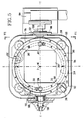
- a paddle assembly 180 includes a frame 182 having an aperture or opening 184 therein.
- the frame 182 has extending therefrom upstanding cylindrical side wall 186 and a pair of respective diametric right and left shaft members 188R and 188L lying on a horizontal axis Y.
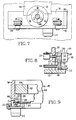
- the shaft members 188R and 188L are rotatably supported in bearing members 190 which are mounted within openings 192 in the opposing pair of side walls 162 of the welding chamber 160 as shown.
- a first drive mechanism 194 is secured to the base 168 of the chamber 160 as shown (Figures 5 and 6) and is coupled to the right shaft member 188R for indexably driving the paddle assembly 180 to any desired angular position within a range of 360° about the Y axis.
- the first drive mechanism 194 may be a DC servomotor such as a model GR6 manufactured by Anorad Corporation, Hauppauge, New York. Such a device is capable of positioning the paddle assembly to an accuracy of 0.036°.
- a carrier 200 is rotatably secured above the apertured frame 182 for rotation about a central axis AC perpendicular to a plane including the aperture 184 of the frame 180 and the transverse axis Y.
- the central axis AC lies along the Z axis as shown in Figure 4.
- the central axis AC lies along the X axis.
- rotation of the carrier 200 will be described as occurring about the X axis or the Z axis.
- the central axis AC may be positioned through a range of 360° about the Y axis.
- the central axis AC is concentric with respect to the aperture 184 in the frame 182.
- the carrier 200 has depending cylindrical wall 202 and a central opening 204 therein which likewise is concentric with the central axis AC and the aperture 184 in the frame 180.
- a lower end of the depending cylindrical wall 202 of the carrier 200 has a circumferential outwardly tapered bearing 206.
- Four circumferentially located, inwardly tapered bearing rollers 208 are mounted to the frame 182 on vertical axes and at 90° intervals as shown in Figure 5.
- the inwardly tapered bearing rollers 208 radially engage the circumferential, outwardly tapered bearing 206 ( Figures 4, 5 and 8) to rotatably support the welding fixture carrier 200 within the paddle 180 as shown.
- a lower end of the depending wall 202 further includes a circumferential spur gear 210 formed below the circumferential outwardly tapered bearing 206 ( Figure 9).
- a second drive mechanism 212 ( Figure 5) including a stepping motor 213 and pinion gear 214 engages the spur gear 210 and is adapted to rotate the carrier 200 to any desired angular position within a range of 360° about the central axis AC ( Figure 4).
- An upper frame member 300 is mounted to an upper portion of depending cylindrical wall 202 ( Figures 5 and 6).
- the upper frame member 300 has a square opening 302 therein which is concentric with the frame aperture 184 along the Z axis.
- the opening 302 corresponds in size and shape to that of the grid 16 described above
- Solenoid 310 is mounted to upstanding wall 186 (Figure 8).
- the solenoid 310 has a spring biased core 312 which is adapted to move radially with respect to the wall 186 and carrier 200.
- the wall 186 has a radial through hole 314 aligned with and sized to receive the core 312.
- Normally the solenoid 310 is de-energized and the core 312 is extended as shown in Figure 8 under the influence of a spring (not shown).
- the free end of the core has a tapered point 316.
- the upper frame member 300 of the carrier 200 has a number of vertically aligned notches 318 (Figure 8) at certain usefully spaced circumferential positions as shown in Figure 5.
- the point 316 of core 312 is located at rest in one of the notches 318 whereby the carrier 200 may be locked in position.
- the solenoid 310 When the solenoid 310 is activated, the core 312 moves radially outward with respect to the carrier 200 and withdraws from the notch 318 whereby the carrier 200 is unlocked.
- the second drive mechanism 212 may be activated to rotate the carrier 200 to any angular position within a range of 360° about the central axis AC as shown, for example, in Figures 4-6. However, certain angular positions have particular advantage and the notches 318 are positioned to allow the carrier to be indexably positioned and conveniently locked at such positions.
- the solenoid 310 is momentarily activated, the core 312 moves radially outward with respect to the carrier 200, and the point 316 withdraws from the notch 318.
- the carrier 200 may thereafter be driven by stepping motor 213 to various angular positions about the Z axis (or the X axis as hereinafter described) and stopped.
- solelynoid 312 If the solenoid 312 is de-energized, the point 316 will move into the next following notch 318 and thereby lock the carrier 200. It is, of course, possible to hold solenoid 310 energized for a time sufficient to bring the carrier 200 to any desired position, including positions between any two notches 318.
- a suitable interlock (not shown but known to those skilled in the art) between solenoid 310 and stepping motor 213 may be provided to avoid operating the stepping motor 213 when the lock is engaged
- notches 318 may be placed at 90° intervals and in some applications at 45° intervals. Other positions may be provided, if desired, and the invention is not limited to the positions shown. Preferably, however, in the application described hereinafter, during laser welding the relative position of the grid 16 with respect to the welding laser beam LB is such that at least one side of the grid 16 is perpendicular to the transverse axis Y and one side is parallel to said Y axis. Notches 318 are thus provided at 90° increments to indexably position and lock the grid 16 as desired. In another application, outer grid straps 22 are disposed 45° with respect to the Y axis and notches 318 are provided at 45° intervals.
- Welding fixture hold-downs 304 are adapted to engage openings or apertures 146 in apertured extensions 144 of the welding fixture 150 ( Figures 3B-3C and Figure 4) so that when installed onto the paddle structure 180 as illustrated in Figure 4, portions of the grid 16 which are to be welded will be located by the welding fixture 150 concentrically at least within the confines of the aperture 302 of the upper frame member 300 and in an overlying plane parallel to the Y axis.
- the chamber 160 is indexably movable in the X-Y direction ( Figure 4) in accordance with the teachings of Wolfe and Antol et al.
- the indexable movement of the chamber 160 is at least co-extensive with the boundaries of the aperture 302 in the upper frame member 300.
- Any point within the square ( Figure 5) defined by the aperture 302 in the upper frame member 300 may be indexably addressed by the laser beam LB which is directed into the chamber 160 along the Z axis as shown in Figures 4 and 6.
- the laser beam LB may weld any one of the grid strap intersections 24, tab 26 and slot 28 locations, and sleeve locations 38 hereinbefore described ( Figures 2A-2D).
- the paddle 180 and welding fixture 150 mounted thereon may be rotated about the Y axis through 360° by means of drive 194 ( Figure 5).
- Figure 5 When rotated 90° from the horizontal position, two of the four outer strap members 22 (Figure 2A) will be positioned in the XY or horizontal plane and the square or large sides of the grid 16 will lie in the YZ or vertical plane. (See, for example, sides B and C in Figure 10B) . Any point on the surface of the uppermost outer grid strap 22 may then be addressed by the laser beam LB as the chamber 160 is incrementally indexed in the XY directions.
- the lowermost one of the outer grid straps 22 may be rotated into the upper position by rotating the paddle 180° about the Y axis, or by rotating the carrier 200 about the central axis AC through an angle of 180° (see Figure 10C, where the central axis AC lies along the X axis).
- the paddle 180 may be utilized to indexably rotate the welding fixture 150 so that sides of the grid 16 perpendicular to the sides described immediately above may be moved into the horizontal plane in the path of the laser beam LB.
- the welding fixture 150 and the grid 16 carried thereby may be rotated 90° about the Z axis and then 90° about the Y axis to place the adjacent pair of opposing outer grid straps 22, in spaced horizontal planes (see, for example, sides E and F in Figures 10F and 10G).
- Each of the outer grid straps 22 may be rotated into the uppermost horizontal position, so that it may be addressed by the laser beam LB, by rotating the frame about the Y axis through an angle of 180° (or by rotating the carrier 200 through an angle of 180° about the central axis AC, which corresponds to the X axis in Figures 10F and 1OG).
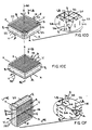
- FIGs 10A-10H For a detailed explanation of the various desired orientations of the grid 16 made possible by the present invention, reference is directed to Figures 10A-10H.
- the grid 16 In Figure 10A the grid 16 is shown in perspective lying in the horizontal or XY plane.
- the welding fixture 150 shown in Figures 3C and 4 and the paddle 180 illustrated in Figures 5-9 are not shown in Figures 10A-10H, although each will be referred to as necessary in order to explain the movements of the grid 16 in Figures 10A-10H.
- the grid 16 is moved into each of the orientations described in Figures 10A-1OH by appropriate movement of apertured frame 182 about the Y axis and movement of carrier 200 about the central axis AC.
- the central axis AC lies along the Z axis or the X axis depending on the orientation of the frame 180 about the Y axis.
- the sides of the grid 16 shall be referred to hereinafter as follows.
- the upper square surface is side A; the lower square surface hidden in Figure 10A is side D; rectangular sides B and C oppose each other; and rectangular sides E and F likewise oppose each other and are perpendicular to the rectangular sides B and C.
- the welding chamber 160 when the grid 16 is in the position shown in Figure 10A the welding chamber 160 ( Figure 4) may be indexed in the XY plane to position the grid 16 with respect to the welding laser beam LB in order to facilitate welding intersections 24 in the side A of the grid straps 20 as shown in the insert to the right of the grid 16 illustrated.
- the frame 180, and thus the grid 16 carried thereby in welding fixture 150 may be rotated from its position in Figure 10A about the Y axis through an angle of 90° so that the outer grid strap 22 (side B) is rotated in the uppermost horizontal plane and is addressed by the laser beam LB operating along the Z axis ( Figure 10B).
- intersections at which the inner grid straps 20 tabs 26 engage slots 28 in the outer grid strap 22 may be addressed and welded by means of the laser LB.
- corner welds 30 may be made.
- the paddle 180 has the aperture 184 in the frame 182 which allows the paddle 180 to be inverted for welding side D through the aperture 184, without removing and repositioning the welding fixture 150 on the paddle 160 and without purging the chamber 160.
- the grid 16 is shown as having been rotated through an angle of 90° about the axis Y from its position in Figure 10C so that side D is addressable by the laser beam LB for making intersection welds at intersections 24 shown in the insert.
- the carrier 200 permits rotation of the welding fixture 150 relative to the paddle 180.
- the grid 16 is shown as having been rotated through an angle of 90° about the central axis AC from its position in Figure 10D by means of corresponding rotation of the carrier 200 ( Figure 4) so that the outer grid straps E and F are parallel with the Y axis. This rotation is in preparation for further rotation of the grid 16 into the orientation illustrated in Figure 10F.
- the grid 16 is shown as having been returned to the original or starting position of Figure 10A by rotating the grid 16 about the Y axis through an angle of 90°, and then rotating the grid 16 about the central axis AC through an angle of 90° from the position in Figure 10G.
- the grid 16 having been welded in all six sides A-F, may be removed from the paddle 180 and chamber 160.
- rotations of the grid 16 about the Y axis are easily accomplished by driving the frame 180 by means of the drive mechanism 194.
- Rotations of the grid 16 about the X and Z axes are accomplished by the rotation of the carrier 200 by means of drive mechanism 212.
- more extensive welding of the grid 16 is required; for example, full lengthwise welds along grid intersections 24. If desired, such full lengthwise welding of grid intersections 24 may be made using the apparatus of the present invention.
- the welding fixture 150 Figure 3C
- the grid 16 is then placed in an open welding fixture 150′ ( Figure 11).
- the open welding fixture 150′ is similar to the welding fixture 150 shown in Figures 3B and 3D, and similar elements have the same reference numerals.
- the retention strap 80 is the same.
- modified vane side welding plate 120′ and modified sleeve side welding plate 140′ each have an apertured grid edge retaining frame portion 121 which has an.open area 123.
- Such an open area 123 allows access by the laser beam LB to the intersections 24 in each cell.
- the described modified welding fixture 150′ is placed on the paddle assembly 180 ( Figure 4) and the carrier 200 rotated about the central axis AC so that sides A, B, C and D lie at a 45° angle relative to the Z axis. Thereafter, the frame 180 carrying welding fixture 150 may be rotated about the Y axis about 19° from the horizontal, thereby exposing the intersections 24 lengthwise to the laser beam LB as shown in Figure 11.
- notches 318 at 45° intervals facilitates a rapid orientation of the grid 16 for lengthwise cell intersection welding. It should be understood that to effect full lengthwise intersection welds in each of the cells, further rotations of the modified welding fixture 150′ about the central axis AC and about the Y axis may be necessary. However, further explanation is deemed unnecessary in view of the previous descriptions herein.
Landscapes
- Engineering & Computer Science (AREA)
- Mechanical Engineering (AREA)
- Physics & Mathematics (AREA)
- Optics & Photonics (AREA)
- Plasma & Fusion (AREA)
- Laser Beam Processing (AREA)
Applications Claiming Priority (2)
| Application Number | Priority Date | Filing Date | Title |
|---|---|---|---|
| US07/091,472 US4825032A (en) | 1987-08-31 | 1987-08-31 | Workpiece handling assembly |
| US91472 | 1987-08-31 |
Publications (2)
| Publication Number | Publication Date |
|---|---|
| EP0305944A1 true EP0305944A1 (de) | 1989-03-08 |
| EP0305944B1 EP0305944B1 (de) | 1992-07-29 |
Family
ID=22227967
Family Applications (1)
| Application Number | Title | Priority Date | Filing Date |
|---|---|---|---|
| EP88114046A Expired EP0305944B1 (de) | 1987-08-31 | 1988-08-29 | Werkstückhandhabungsaufbau |
Country Status (5)
| Country | Link |
|---|---|
| US (1) | US4825032A (de) |
| EP (1) | EP0305944B1 (de) |
| JP (1) | JP2585742B2 (de) |
| DE (1) | DE3873224T2 (de) |
| ES (1) | ES2034075T3 (de) |
Cited By (4)
| Publication number | Priority date | Publication date | Assignee | Title |
|---|---|---|---|---|
| EP0751529A1 (de) * | 1995-06-29 | 1997-01-02 | Franco-Belge De Fabrication De Combustible Fbfc | Verfahren und Vorrichtung zum Verschweissen von ausserhalb von sich kreuzendem Stegen eines Abstandhaltergitters für Kernbrennstabbündel |
| EP0751528A1 (de) * | 1995-06-29 | 1997-01-02 | Societe Franco-Belge De Fabrication De Combustibles Fbfc | Verfahren und Einrichtung zum Verschweissen eines Abstandhaltergitters eines Kernreaktorbrennstabbündels und Vorrichtung zum Verschweissen vom Gitterinnenraum |
| EP1262275A1 (de) * | 2001-05-29 | 2002-12-04 | Maschinenfabrik Berthold Hermle Aktiengesellschaft | Werkstückhalteeinrichtung für Bearbeitungsmaschinen, insbesondere Fräs- und/oder Bohrmaschinen |
| CN101073856B (zh) * | 2006-05-19 | 2010-05-26 | 韩国原子力研究所 | 焊接条带连接部的装置和方法、及使用其制造的定位格架 |
Families Citing this family (11)
| Publication number | Priority date | Publication date | Assignee | Title |
|---|---|---|---|---|
| BG46808A1 (en) * | 1988-05-27 | 1990-03-15 | Univ Plovdivski | Device for laser engraving |
| JP2807361B2 (ja) * | 1991-09-19 | 1998-10-08 | 株式会社東芝 | 使用済燃料貯蔵ラックとその製造方法 |
| JP3074930B2 (ja) * | 1992-04-09 | 2000-08-07 | トヨタ自動車株式会社 | 2種類以上を製造可能な溶接パネル製造装置 |
| NZ331434A (en) * | 1998-08-19 | 2001-02-23 | Sullivan & Haddon Group Ltd | Elongate building materials such as metal beams, bars and tubes, and process for making them |
| EP1140420B1 (de) | 1999-01-11 | 2003-10-01 | Amada Company, Limited | Blechbearbeitungssysteme und verfahren zum überführen eines werkstückes in einem dieser systeme |
| US6560890B1 (en) | 2002-02-21 | 2003-05-13 | General Electric Company | Fixture for locating and clamping a part for laser drilling |
| US7127309B2 (en) * | 2004-02-10 | 2006-10-24 | Stratasys, Inc. | Modeling apparatus with tray substrate |
| KR100922162B1 (ko) * | 2007-09-28 | 2009-10-21 | 한전원자력연료 주식회사 | 핵연료집합체 지지격자의 레이저용접장치 |
| KR100952183B1 (ko) * | 2007-09-28 | 2010-04-09 | 한전원자력연료 주식회사 | 용접치구 자동 장입 및 인출 장치 |
| WO2014152851A2 (en) * | 2013-03-14 | 2014-09-25 | Babcock & Wilcox Mpower, Inc. | Spacer grid welding fixtrue |
| CN108312506A (zh) * | 2017-12-29 | 2018-07-24 | 网云(武汉)三维科技股份有限公司 | 一种粉末粘接3d打印机 |
Citations (5)
| Publication number | Priority date | Publication date | Assignee | Title |
|---|---|---|---|---|
| EP0074517A2 (de) * | 1981-09-15 | 1983-03-23 | Wilhelm Severt | Spann- und Wendevorrichtung |
| US4492844A (en) * | 1982-09-01 | 1985-01-08 | Westinghouse Electric Corp. | Welding plates for a fuel rod grid |
| US4493967A (en) * | 1982-09-01 | 1985-01-15 | Westinghouse Electric Corp. | Rigid support for laser machining apparatus |
| US4501949A (en) * | 1982-09-01 | 1985-02-26 | Westinghouse Electric Corp. | Movable machining chamber with rotatable work piece fixture |
| FR2561151A1 (fr) * | 1984-03-13 | 1985-09-20 | Fragema Framatome & Cogema | Procede et installation de soudage de grilles pour assemblage de combustible nucleaire |
Family Cites Families (2)
| Publication number | Priority date | Publication date | Assignee | Title |
|---|---|---|---|---|
| US4054772A (en) * | 1973-10-24 | 1977-10-18 | Dresser Industries, Inc. | Positioning system for rock bit welding |
| JP5823839B2 (ja) | 2011-11-29 | 2015-11-25 | 久保田 眞知子 | てんぷら等油飛散から手腕を守るカバー付き揚げ物挟み |
-
1987
- 1987-08-31 US US07/091,472 patent/US4825032A/en not_active Expired - Fee Related
-
1988
- 1988-08-29 EP EP88114046A patent/EP0305944B1/de not_active Expired
- 1988-08-29 DE DE8888114046T patent/DE3873224T2/de not_active Expired - Fee Related
- 1988-08-29 ES ES198888114046T patent/ES2034075T3/es not_active Expired - Lifetime
- 1988-08-29 JP JP63212666A patent/JP2585742B2/ja not_active Expired - Lifetime
Patent Citations (5)
| Publication number | Priority date | Publication date | Assignee | Title |
|---|---|---|---|---|
| EP0074517A2 (de) * | 1981-09-15 | 1983-03-23 | Wilhelm Severt | Spann- und Wendevorrichtung |
| US4492844A (en) * | 1982-09-01 | 1985-01-08 | Westinghouse Electric Corp. | Welding plates for a fuel rod grid |
| US4493967A (en) * | 1982-09-01 | 1985-01-15 | Westinghouse Electric Corp. | Rigid support for laser machining apparatus |
| US4501949A (en) * | 1982-09-01 | 1985-02-26 | Westinghouse Electric Corp. | Movable machining chamber with rotatable work piece fixture |
| FR2561151A1 (fr) * | 1984-03-13 | 1985-09-20 | Fragema Framatome & Cogema | Procede et installation de soudage de grilles pour assemblage de combustible nucleaire |
Cited By (9)
| Publication number | Priority date | Publication date | Assignee | Title |
|---|---|---|---|---|
| EP0751529A1 (de) * | 1995-06-29 | 1997-01-02 | Franco-Belge De Fabrication De Combustible Fbfc | Verfahren und Vorrichtung zum Verschweissen von ausserhalb von sich kreuzendem Stegen eines Abstandhaltergitters für Kernbrennstabbündel |
| EP0751528A1 (de) * | 1995-06-29 | 1997-01-02 | Societe Franco-Belge De Fabrication De Combustibles Fbfc | Verfahren und Einrichtung zum Verschweissen eines Abstandhaltergitters eines Kernreaktorbrennstabbündels und Vorrichtung zum Verschweissen vom Gitterinnenraum |
| FR2736192A1 (fr) * | 1995-06-29 | 1997-01-03 | Franco Belge Combustibles | Procede et dispositif de soudage de plaquettes entrecroisees d'une grille-entretoise d'un assemblage de combustible par l'exterieur de la grille |
| FR2736191A1 (fr) * | 1995-06-29 | 1997-01-03 | Franco Belge Combustibles | Procede et installation de soudage d'une grille-entretoise d'un assemblage de combustible pour un reacteur nucleaire et dispositif de soudage par l'interieur d'une grille |
| US5726418A (en) * | 1995-06-29 | 1998-03-10 | Franco-Belge De Fabrication De Combustible-Fbfc | Method and installation for laser welding a spacer grid of a fuel assembly for a nuclear reactor, and device for welding via the interior of a grid |
| US5808271A (en) * | 1995-06-29 | 1998-09-15 | Franco-Belge de Fabrication de Combustible--FBFC | Method of laser beam welding interlaced straps of a spacer grid with plural beams |
| EP1262275A1 (de) * | 2001-05-29 | 2002-12-04 | Maschinenfabrik Berthold Hermle Aktiengesellschaft | Werkstückhalteeinrichtung für Bearbeitungsmaschinen, insbesondere Fräs- und/oder Bohrmaschinen |
| US6733217B2 (en) | 2001-05-29 | 2004-05-11 | Maschinenfabrik Berthold Hermle Ag | Workpiece holding means for machine tools and more especially for milling and/or drilling machines |
| CN101073856B (zh) * | 2006-05-19 | 2010-05-26 | 韩国原子力研究所 | 焊接条带连接部的装置和方法、及使用其制造的定位格架 |
Also Published As
| Publication number | Publication date |
|---|---|
| US4825032A (en) | 1989-04-25 |
| ES2034075T3 (es) | 1993-04-01 |
| EP0305944B1 (de) | 1992-07-29 |
| DE3873224T2 (de) | 1993-03-11 |
| JP2585742B2 (ja) | 1997-02-26 |
| JPS6471589A (en) | 1989-03-16 |
| DE3873224D1 (de) | 1992-09-03 |
Similar Documents
| Publication | Publication Date | Title |
|---|---|---|
| EP0305944B1 (de) | Werkstückhandhabungsaufbau | |
| AU751870B2 (en) | Engraving system | |
| US4680443A (en) | Process and apparatus for electron beam welding grids for a nuclear fuel assembly | |
| EP0372789A2 (de) | Apparat zum Schneiden von komplizierten Ausschnitten in dünnwandigen rohrförmigen Teilen | |
| US5099134A (en) | Collimator and a method of producing a collimator for a scintillator | |
| US4885127A (en) | Nuclear fuel rod support grid with attachable spring and dimple support spacers | |
| EP0103444B1 (de) | Brennstoffabstandshalter mit in eingekerbten Bändern geschweisten Hülsen | |
| US3933583A (en) | Nuclear fuel rod frame with fuel rods positioned by moveable member | |
| US3665586A (en) | Nuclear fuel rod supporting arrangements | |
| KR20030071759A (ko) | 액체 정밀 취급 기구용 플레이트 로케이터 | |
| JPH029550B2 (de) | ||
| JPH029556B2 (de) | ||
| US4137125A (en) | Method of welding nuclear reactor fuel assemblies | |
| JPH029557B2 (de) | ||
| JP2531808B2 (ja) | 管理された環境中において部品集合体を自動的に溶接するための装置 | |
| JPS5997779A (ja) | 核燃料集合体用格子の溶接方法及び装置 | |
| JPS58113894A (ja) | 燃料ラツクモジユ−ル | |
| US5398264A (en) | Grid welding fixture for a spacer grid | |
| EP0336153A2 (de) | Aussensteg für nuklearen Brennstoffabstandshalter | |
| US4101752A (en) | Process for welding corner cells in fuel assembly grids | |
| JPH0212677B2 (de) | ||
| US4556776A (en) | Welding fixture for nuclear reactor fuel assembly grid | |
| EP0797217B1 (de) | Vorrichtung zur Befestigung eines Abstandhalters auf einem Wasserrohr mit nicht-rundem Querschnitt | |
| JP3139921B2 (ja) | 使用済燃料貯蔵ラックの製造方法とその製造装置 | |
| JPH0769449B2 (ja) | 独立セル型燃料スペーサおよびその製造方法 |
Legal Events
| Date | Code | Title | Description |
|---|---|---|---|
| PUAI | Public reference made under article 153(3) epc to a published international application that has entered the european phase |
Free format text: ORIGINAL CODE: 0009012 |
|
| AK | Designated contracting states |
Kind code of ref document: A1 Designated state(s): BE DE ES FR GB IT SE |
|
| 17P | Request for examination filed |
Effective date: 19890816 |
|
| 17Q | First examination report despatched |
Effective date: 19901016 |
|
| ITF | It: translation for a ep patent filed | ||
| GRAA | (expected) grant |
Free format text: ORIGINAL CODE: 0009210 |
|
| AK | Designated contracting states |
Kind code of ref document: B1 Designated state(s): BE DE ES FR GB IT SE |
|
| ET | Fr: translation filed | ||
| REF | Corresponds to: |
Ref document number: 3873224 Country of ref document: DE Date of ref document: 19920903 |
|
| REG | Reference to a national code |
Ref country code: ES Ref legal event code: FG2A Ref document number: 2034075 Country of ref document: ES Kind code of ref document: T3 |
|
| PLBE | No opposition filed within time limit |
Free format text: ORIGINAL CODE: 0009261 |
|
| STAA | Information on the status of an ep patent application or granted ep patent |
Free format text: STATUS: NO OPPOSITION FILED WITHIN TIME LIMIT |
|
| 26N | No opposition filed | ||
| EAL | Se: european patent in force in sweden |
Ref document number: 88114046.1 |
|
| PGFP | Annual fee paid to national office [announced via postgrant information from national office to epo] |
Ref country code: SE Payment date: 19970717 Year of fee payment: 10 |
|
| PGFP | Annual fee paid to national office [announced via postgrant information from national office to epo] |
Ref country code: FR Payment date: 19970812 Year of fee payment: 10 |
|
| PGFP | Annual fee paid to national office [announced via postgrant information from national office to epo] |
Ref country code: ES Payment date: 19970821 Year of fee payment: 10 |
|
| PGFP | Annual fee paid to national office [announced via postgrant information from national office to epo] |
Ref country code: DE Payment date: 19970827 Year of fee payment: 10 |
|
| PGFP | Annual fee paid to national office [announced via postgrant information from national office to epo] |
Ref country code: BE Payment date: 19970908 Year of fee payment: 10 |
|
| PG25 | Lapsed in a contracting state [announced via postgrant information from national office to epo] |
Ref country code: SE Free format text: LAPSE BECAUSE OF NON-PAYMENT OF DUE FEES Effective date: 19980830 Ref country code: ES Free format text: LAPSE BECAUSE OF NON-PAYMENT OF DUE FEES Effective date: 19980830 |
|
| PG25 | Lapsed in a contracting state [announced via postgrant information from national office to epo] |
Ref country code: BE Free format text: LAPSE BECAUSE OF NON-PAYMENT OF DUE FEES Effective date: 19980831 |
|
| BERE | Be: lapsed |
Owner name: WESTINGHOUSE ELECTRIC CORP. Effective date: 19980831 |
|
| PG25 | Lapsed in a contracting state [announced via postgrant information from national office to epo] |
Ref country code: FR Free format text: LAPSE BECAUSE OF NON-PAYMENT OF DUE FEES Effective date: 19990430 |
|
| EUG | Se: european patent has lapsed |
Ref document number: 88114046.1 |
|
| PG25 | Lapsed in a contracting state [announced via postgrant information from national office to epo] |
Ref country code: DE Free format text: LAPSE BECAUSE OF NON-PAYMENT OF DUE FEES Effective date: 19990601 |
|
| REG | Reference to a national code |
Ref country code: FR Ref legal event code: ST |
|
| REG | Reference to a national code |
Ref country code: GB Ref legal event code: IF02 |
|
| REG | Reference to a national code |
Ref country code: ES Ref legal event code: FD2A Effective date: 19990910 |
|
| PGFP | Annual fee paid to national office [announced via postgrant information from national office to epo] |
Ref country code: GB Payment date: 20040726 Year of fee payment: 17 |
|
| PG25 | Lapsed in a contracting state [announced via postgrant information from national office to epo] |
Ref country code: IT Free format text: LAPSE BECAUSE OF NON-PAYMENT OF DUE FEES Effective date: 20050829 Ref country code: GB Free format text: LAPSE BECAUSE OF NON-PAYMENT OF DUE FEES Effective date: 20050829 |
|
| GBPC | Gb: european patent ceased through non-payment of renewal fee |
Effective date: 20050829 |