EP0305489B1 - Shock and vibration isolation mounting - Google Patents
Shock and vibration isolation mounting Download PDFInfo
- Publication number
- EP0305489B1 EP0305489B1 EP88903057A EP88903057A EP0305489B1 EP 0305489 B1 EP0305489 B1 EP 0305489B1 EP 88903057 A EP88903057 A EP 88903057A EP 88903057 A EP88903057 A EP 88903057A EP 0305489 B1 EP0305489 B1 EP 0305489B1
- Authority
- EP
- European Patent Office
- Prior art keywords
- channel member
- members
- base
- transverse
- channel
- Prior art date
- Legal status (The legal status is an assumption and is not a legal conclusion. Google has not performed a legal analysis and makes no representation as to the accuracy of the status listed.)
- Expired
Links
Images

Classifications
-
- F—MECHANICAL ENGINEERING; LIGHTING; HEATING; WEAPONS; BLASTING
- F16—ENGINEERING ELEMENTS AND UNITS; GENERAL MEASURES FOR PRODUCING AND MAINTAINING EFFECTIVE FUNCTIONING OF MACHINES OR INSTALLATIONS; THERMAL INSULATION IN GENERAL
- F16F—SPRINGS; SHOCK-ABSORBERS; MEANS FOR DAMPING VIBRATION
- F16F7/00—Vibration-dampers; Shock-absorbers
-
- F—MECHANICAL ENGINEERING; LIGHTING; HEATING; WEAPONS; BLASTING
- F16—ENGINEERING ELEMENTS AND UNITS; GENERAL MEASURES FOR PRODUCING AND MAINTAINING EFFECTIVE FUNCTIONING OF MACHINES OR INSTALLATIONS; THERMAL INSULATION IN GENERAL
- F16F—SPRINGS; SHOCK-ABSORBERS; MEANS FOR DAMPING VIBRATION
- F16F15/00—Suppression of vibrations in systems; Means or arrangements for avoiding or reducing out-of-balance forces, e.g. due to motion
- F16F15/02—Suppression of vibrations of non-rotating, e.g. reciprocating systems; Suppression of vibrations of rotating systems by use of members not moving with the rotating systems
- F16F15/04—Suppression of vibrations of non-rotating, e.g. reciprocating systems; Suppression of vibrations of rotating systems by use of members not moving with the rotating systems using elastic means
- F16F15/08—Suppression of vibrations of non-rotating, e.g. reciprocating systems; Suppression of vibrations of rotating systems by use of members not moving with the rotating systems using elastic means with rubber springs ; with springs made of rubber and metal
-
- G—PHYSICS
- G11—INFORMATION STORAGE
- G11B—INFORMATION STORAGE BASED ON RELATIVE MOVEMENT BETWEEN RECORD CARRIER AND TRANSDUCER
- G11B33/00—Constructional parts, details or accessories not provided for in the other groups of this subclass
- G11B33/02—Cabinets; Cases; Stands; Disposition of apparatus therein or thereon
- G11B33/08—Insulation or absorption of undesired vibrations or sounds
Definitions
- the present invention relates to shock and vibration mounting systems and, more particularly to a shock and vibration isolation mounting apparatus for releasably mounting a box-like article such as a computer disk drive or the like to a chassis.
- mass storage drives such as disk drives
- mass storage drives include read/write heads mounted on the ends of lightweight arms, which can be adjacent the easily damaged magnetic surface of the disks therein at the time a shock wave is transferred into the drive. So-called "crashing" of the heads into the magnetic surface can cause catastrophic and unrepairable damage to the disk.
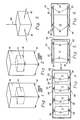
- shock and vibration isolation has been provided by using shock casters such as those indicates as 10 on the computer 12 of Figure 1.
- shock casters such as those indicates as 10 on the computer 12 of Figure 1.
- any shock or vibration induced into the computer 12 is passed directly into the disk drive 14.
- any shock to the computer 12 itself and not to the other side of the shock casters 10 is not even affected by the shock casters 10.
- the shock casters may end up actually amplifying shock and vibration inputs to the computer chassis with the lightest configurations. In some factory environments, shock isolated floors are even installed to isolate larger commercial sized computers.
- shock absorbing feet 16 are mounted between the chassis of the computer 12 and the drive 14, or the like, as shown in Figure 2, there are many problems ; not the least of which is the inability to install and remove the drive. For example, one can appreciate that in an installation such as that shown in simplified form in Figure 2, with shock absorbing feet 16 at each of the corners of the base of the drive 14 for complete support, there must be access from various points in order to install or remove the drive 14. If shock isolation is to be optimized for each drive, the feet 16 must be associated therewith.
- US-A-4 260 208 discloses an elastic fixture for magnetic discs in which the disc lies on four compressed rubber pads. There are no rubber pads in tension which would optimize shock isolation. Also, the mounting frame is not very rigid and is attached to mobile rails of a cabinet through screws near each rubber pad, which differs from the invention.
- Figure 3 depicts in simplified form the shocks that must be considered in a optimized mounting system. There are front to back forces as indicated by the arrow 18 ; side to side forces as indicated by the arrow 20 ; and vertical forces as indicated by the arrow 22.
- the present invention provides a shock and vibration isolation mounting apparatus for releaseably mounting an article in a box with a top and a bottom surface and comprising at least one pair of mounting assemblies for attaching to the article and the box (24), each of said mounting assemblies comprising first and second elongated rigid U-shaped channel members, and elastomeric members characterized in that one of said pair of mounting assemblies is disposed below said article and the other pair of mounting assemblies is disposed above said article and wherein each of the mounting assemblies comprises, in combination :
- the bolt means is a spring-loaded captive bolt carried by the transverse member of the second channel member.
- first and second elastomeric members which are carried by the first channel member on the base between the sides and adjacent respective ends.
- the elastomeric members include means for attaching the first channel member to the adjacent surface such as a captive bolt carried perpendicular to the base.
- the ends of the first and second channel members opposite the transverse members include engageable interactive means for drawing the ends together and for holding them tightly together as the threaded bolt means pulls the transverse members towards one another.
- those means comprise the ends of the sides of the second channel member angling at about 45° back towards the base and the ends of the sides of the first channel member including outward facing tabs angling at about 45° back towards the base so that as the threaded bolt means pulls the transverse members towards one another the angled ends of the second channel member engage respective ones of the tabs of the first channel member and wedgedly force the bases of the first and second channel members tightly towards one another.
- Figure 1 is a perspective view showing one prior art manner of providing shock mounting for a disk drive within a computer.
- Figure 2 is a perspective view showing another prior art manner of shock mounting a disk drive within a computer.
- Figure 3 is a simplified perspective view of a computer disk drive showing the forces that must be taken into consideration in a shock mounting system.
- Figure 4 is a simplified front view of the invention of the present invention in its preferred embodiment used to mount a pair of computer disk drives.
- Figure 5 is a side view of the apparatus of Figure 4 in the inserted and locked position.
- Figure 6 is a side view of the apparatus of Figure 4 showing the disk drive in the process of being inserted or removed with access only from the front as it is possible with the present invention.
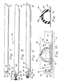
- Figure 7 is a side view of the inner channel member of the present invention.
- Figure 8 is a side view of the outer channel member of the present invention.
- Figure 9 is a partially cutaway side view of the inner and outer channel members in their engaged position.
- Figure 10 is an enlarged partially cutaway view of the inner channel member of the present invention with one of the elastomeric members mounted thereto.
- Figure 11 is a cutaway view through the elastomeric member of Figure 9.
- Figure 12 is a partially cutaway view of the inner channel member showing the elastomeric members attached thereto adjacent the ends thereof.
- Figure 13 is a top view of the threadedly engaging ends of the inner and outer channel members slidablely mated but not connected together as during insertion or removal of the disk drive.
- Figure 14 is a side view of the present invention in its preferred manner of use with the elastomeric members under tension from the top and compression from the bottom.
- FIG. 4 The present invention and its manner of operation is shown in simplified form in Figures 4-6.
- the present invention permits the mounting, insertion and removal of multiple drives with access from only one side.
- the two drives 14 are shown disposed within a box 24 having an opposed top and bottom 90, respectively, along with a back 30 and opposed sides 32.
- the front 34 is shown as being the open side through which installation is affected.
- Each drive 14 is mounted between two pair of mounting assemblies 36. One pair is connected between the top of the drive 14 and the top 26 of the box 24 while the other is connected between the bottom of the drive 14 and the bottom 90 of the box 24.
- Each mounting assembly 36 includes an elastomeric member 80. Because of the unique two pair configuration, the upper elastomeric members 80 are in tension while the lower members 80 are in compression. As will be appreciated from the discussion hereinafter, this configuration accounts for all the force vectors of Figure 3.
- the mounting assemblies 36 lock together as shown in Figure 5 to place all the shock and vibration absorption on the elastomeric members 80; and, release to allow the drive 14 and elastomeric members 80 to slide in and out for change of the drive 14 and/or the members 80 to affect optimum isolation.
- the construction of the mounting assemblies 36 will now be described in greater detail.
- each mounting assembly 36 has an elongated inner rigid channel member 40 of steel, or the like, as shown in side view in Figure 7.
- the inner channel member 40 is generally U-shaped and comprises a base 42 separating a pair of parallel sides 44 perpendiculr to the base.
- a transverse member 46 extends across one end perpendicular to the base 42 and sides 44.
- Each mounting assembly 36 also has an elongated outer rigid channel member 56 of steel, or the like, as shown in side view in Figure 8.
- the outer channel member 56 is also generally U-shaped and, like the inner member 40, comprises a base 58 separating a pair of parallel sides 60 perpendicular to the base.
- a transverse member 62 extends across one end perpendicular to the base 58 and sides 60.
- a spring-loaded bolt assembly 66 is concentrically connected to the bore 64.
- Bolt assembly 66 is of well known design and comprises a collar 68 press fit into the bore 64 and slidably carrying a shaft 70 having a knurled and slotted head 72, a threaded opposite end 74 adapted to threadedly engage the threaded bore 52, and a bias spring 76 urging the head outward.
- the ends 78 of the sides 60 angle back towards the base 58 at about a 45° angle.
- the angled ends 78 form the other half of means for causing the components to be drawn and held together.
- the inner and outer channel members 40, 56 slidably fit together with the base 42 of the inner member 40 disposed on the base 58 of the outer member 56 and with sides 44 between sides 60.
- the threaded end 74 of the bolt assembly 66 can be pushed into engagement with the threaded bore 52.
- the transverse members 46, 62 can be pulled towards one another.
- the angled ends 78 of the outer member 56 also contact the tabs 54 of the inner member 40.
- the angled ends 78 tend to ride up the tabs 54 drawing and holdilng the inner and outer channel members 40, 56 tightly together on that end as well.
- the members 40, 56 are held tightly together along their entire length.
- the inner channel member 40 is provided with a pair of elastomeric members 80 disposed adjacent the respective ends thereof as shown in Figures 10-13.
- Each elastomeric member 80 comprises a block 82 of rubber, or the like, as appropriate for the particular application.
- the manner of construction of the block 82 to achieve shock and vibration damping with particular loads is well known to those skilled in the art, and per se, forms no part of the present invention. In the interest of simplicity and to avoid redundancy, therefore, no further details of the construction and materials of the blocks 82 will be provided herein.
- Each block 82 is bonded to a metal base plate 84 by which it can be mounted to the base 42 of the inner channel member 40 as with rivets 86.
- each block 82 is bonded to a metal base plate 84 by which it can be mounted to the base 42 of the inner channel member 40 as with rivets 86.
- a flexible metal grounding strip 87 be fastened to the inner channel member 40 for grounding same. This is conveniently done with a rear rivet 86 as shown in Figure 12.
- Each block 82 also carries a captive bolt 88 perpendicular to the base 42, as best seen with reference to Figure 11, whereby to attach the inner channel member 40 to the top and bottom 26, 28 of the computer chassis, as indicated by the ghosted lines 90.
- the outer channel member 56 can be provided with chamfered holes 92 therethrough as shown in Figure 13, integral mounting tabs, or the like, by which the outer channel member 56 can be attached to the disk drive case, indicated by the ghosted lines 94 in Figure 14, using flat headed screws or bolts (not shown).
- FIG 14 wherein a disk drive 14 is disposed between two pair of mounting assemblies 36 in the manner of the simplified drawings of Figures 4-6.
- the upper elastomeric members 80 are in tension while the lower elastomeric members 80 are in compression.
- This provides for optimum isolation from all the various shock and vibration force vectors as described previously with respect to Figure 3.
- the elastomeric members 80 attached to the computer chassis can easily be changed by backing out the captive bolts 88.
- the disk drive 14 with the outer channel members 56 attached thereto can be slid onto the inner channel members 40, as previously described and as indicated in Figure 13, and a screwdriver used to engage the head 72 of the bolt assembly 66 to tighten (or untighten) it. Removal is, of course, just as easy and merely a reverse of the insertion process.
- the present invention has truly met its stated objectives by providing a method and apparatus for mounting objectives by providing a method and apparatus for mounting a computer disk drive, or the like, which provides optimum isolation from shock and vibratin while allowing insertion and/or removal with full access from only one side.
Landscapes
- Engineering & Computer Science (AREA)
- General Engineering & Computer Science (AREA)
- Mechanical Engineering (AREA)
- Chemical & Material Sciences (AREA)
- Combustion & Propulsion (AREA)
- Physics & Mathematics (AREA)
- Acoustics & Sound (AREA)
- Aviation & Aerospace Engineering (AREA)
- Vibration Prevention Devices (AREA)
Applications Claiming Priority (2)
| Application Number | Priority Date | Filing Date | Title |
|---|---|---|---|
| US29328 | 1987-03-23 | ||
| US07/029,328 US4705257A (en) | 1987-03-23 | 1987-03-23 | Shock and vibration isolation mounting |
Publications (2)
| Publication Number | Publication Date |
|---|---|
| EP0305489A1 EP0305489A1 (en) | 1989-03-08 |
| EP0305489B1 true EP0305489B1 (en) | 1991-10-09 |
Family
ID=21848479
Family Applications (1)
| Application Number | Title | Priority Date | Filing Date |
|---|---|---|---|
| EP88903057A Expired EP0305489B1 (en) | 1987-03-23 | 1988-03-01 | Shock and vibration isolation mounting |
Country Status (6)
| Country | Link |
|---|---|
| US (1) | US4705257A (enExample) |
| EP (1) | EP0305489B1 (enExample) |
| JP (1) | JPH01501429A (enExample) |
| CA (1) | CA1283730C (enExample) |
| DE (1) | DE3865404D1 (enExample) |
| WO (1) | WO1988007748A1 (enExample) |
Families Citing this family (46)
| Publication number | Priority date | Publication date | Assignee | Title |
|---|---|---|---|---|
| US4834060A (en) * | 1987-03-25 | 1989-05-30 | Tennis Tutor, Inc. | Hand carried battery powered ball throwing apparatus |
| US4937806A (en) * | 1988-02-12 | 1990-06-26 | Mdb Systems, Inc. | Shock-isolated portable mass data storage device |
| AT392702B (de) * | 1989-08-29 | 1991-05-27 | Philips Nv | Aufzeichnungs- und/oder wiedergabegeraet |
| US5040953A (en) * | 1988-09-19 | 1991-08-20 | Copeland Corporation | Mounting system |
| JP2785279B2 (ja) * | 1988-09-26 | 1998-08-13 | ソニー株式会社 | ディスクカートリッジ |
| US4980786A (en) * | 1988-11-14 | 1990-12-25 | Maxtor Corporation | Method and apparatus for improved thermal isolation and stability of disk drives |
| US5333098A (en) * | 1992-02-03 | 1994-07-26 | Digital Equipment Corporation | Shock absorbing apparatus for mounting a plurality of storage devices in a stacked configuration |
| US5400196A (en) * | 1992-04-30 | 1995-03-21 | International Business Machines Corporation | DASD with spindle imbalance isolation and method for producing same |
| JPH0666111B2 (ja) * | 1992-05-12 | 1994-08-24 | インターナショナル・ビジネス・マシーンズ・コーポレイション | 耐衝撃性可搬型ディスク記憶装置 |
| US5289348A (en) * | 1992-11-19 | 1994-02-22 | Harold R. Miller | Shock absorbing rack system |
| US5430607A (en) * | 1992-12-31 | 1995-07-04 | North Atlantic Industries, Inc. | Rugged modular portable computer including modules hinged along an edge |
| US5335995A (en) * | 1993-07-16 | 1994-08-09 | Servo Corporation Of America | Resilient support for a railroad wheel heat sensor |
| KR950030643A (ko) * | 1994-04-27 | 1995-11-24 | 김광호 | 화면크기 전환장치 |
| US5631506A (en) * | 1994-12-14 | 1997-05-20 | Tritium Technologies | Sloped facet electromagnetic actuator adapted for vibration compensation |
| JP3029383B2 (ja) * | 1995-01-31 | 2000-04-04 | 株式会社東芝 | 磁気ディスク装置の取付け方法及び取付け構造 |
| US5751551A (en) * | 1995-11-07 | 1998-05-12 | Sun Microsystems, Inc. | Universal hard drive bracket with shock and vibrational isolation and electrical grounding |
| US6021041A (en) * | 1997-06-09 | 2000-02-01 | Dell U.S.A., L.P | Tuned shock absorbing system for portable computer hard disc drives |
| US6028766A (en) * | 1997-07-18 | 2000-02-22 | Hewlett-Packard Company | Strategically placed compliance bumps for shock attentuation |
| US6134113A (en) * | 1997-08-28 | 2000-10-17 | Mills; Richard E. | Energy absorbing viscoelastic spacer for reducing vibration to disk drives |
| US6166901A (en) * | 1998-03-13 | 2000-12-26 | International Business Machines Corporation | Vibration dampening system for removable hard disk drive carriers |
| US6015196A (en) * | 1998-03-26 | 2000-01-18 | Pacific Micro Data, Inc. | Module mounting system |
| US6262888B1 (en) | 1999-06-30 | 2001-07-17 | Dell Usa, L.P. | Impact damping system for peripheral device |
| US6999909B1 (en) | 1999-10-28 | 2006-02-14 | Seagate Technology Llc | Process for designing an optimal vibration isolation mount for a disc drive |
| US6310769B1 (en) | 2000-05-03 | 2001-10-30 | Dell Products L.P. | Mounting bracket assembly for system components in a computer |
| US6505806B1 (en) * | 2000-05-09 | 2003-01-14 | Husky Injection Molding Systems, Ltd. | Dynamic machine mount |
| US6717762B1 (en) | 2000-06-09 | 2004-04-06 | Iomega Corporation | Method and apparatus for making a drive compatible with a removable cartridge |
| US6633445B1 (en) | 2000-06-09 | 2003-10-14 | Iomega Corporation | Method and apparatus for electrically coupling components in a removable cartridge |
| US6628474B1 (en) | 2000-06-09 | 2003-09-30 | Iomega Corporation | Method and apparatus for electrostatic discharge protection in a removable cartridge |
| US6624979B1 (en) | 2000-06-09 | 2003-09-23 | Iomega Corporation | Method and apparatus for parking and releasing a magnetic head |
| JP2002093136A (ja) * | 2000-09-04 | 2002-03-29 | Internatl Business Mach Corp <Ibm> | 携帯電子機器、ディスク・ドライブ装置、装着体およびコンピュータ装置の筐体 |
| US6781782B2 (en) | 2000-12-21 | 2004-08-24 | Iomega Corporation | Method and apparatus for saving calibration parameters for a removable cartridge |
| US6675148B2 (en) | 2001-01-05 | 2004-01-06 | Digital Voice Systems, Inc. | Lossless audio coder |
| US6496362B2 (en) * | 2001-05-14 | 2002-12-17 | Iomega Corporation | Method and apparatus for protecting a hard disk drive from shock |
| US6779067B2 (en) | 2001-05-14 | 2004-08-17 | Iomega Corporation | Method and apparatus for providing extended functionality for a bus |
| US6901525B2 (en) | 2001-05-25 | 2005-05-31 | Iomega Corporation | Method and apparatus for managing power consumption on a bus |
| US8131389B1 (en) | 2002-02-08 | 2012-03-06 | Digital Voice Systems, Inc. | Digital audio server |
| US7054153B2 (en) * | 2003-10-31 | 2006-05-30 | Hewlett-Packard Development Company, L.P. | Mount for computer drive |
| US7064908B2 (en) * | 2004-04-21 | 2006-06-20 | The Boeing Company | Laser beam jitter reduction device on a laser optical bench |
| CN201138570Y (zh) * | 2007-08-10 | 2008-10-22 | 鸿富锦精密工业(深圳)有限公司 | 数据存储器减震装置 |
| TWI473082B (zh) * | 2009-12-01 | 2015-02-11 | Hon Hai Prec Ind Co Ltd | 資料存儲裝置 |
| JP5296815B2 (ja) * | 2011-01-25 | 2013-09-25 | 株式会社バッファロー | 収容ケース |
| US8720350B2 (en) * | 2012-09-27 | 2014-05-13 | Xyratex Technology Limited | Pallet, method of manufacturing and method of transporting or handling goods |
| US9332670B1 (en) * | 2012-11-20 | 2016-05-03 | Amazon Technologies, Inc. | Data center module with leveling pad |
| CN108200488B (zh) * | 2016-12-08 | 2022-06-03 | 林球有限公司 | 用于音响器材的防振装置及具有防振装置的音响器材架 |
| US10096343B1 (en) * | 2017-07-26 | 2018-10-09 | Arris Enterprises Llc | Shock absorbing bracket assembly for storage media device |
| CN107920034B (zh) * | 2017-11-16 | 2020-11-06 | 常州信息职业技术学院 | 一种稳定性好的网络交换机 |
Family Cites Families (12)
| Publication number | Priority date | Publication date | Assignee | Title |
|---|---|---|---|---|
| US1136071A (en) * | 1913-12-18 | 1915-04-20 | Yawman & Erbe Mfg Co | Metallic-furniture drawer. |
| US2386248A (en) * | 1939-01-18 | 1945-10-09 | Marzetti Manlio | Means for resilient mounting of units |
| US2514246A (en) * | 1947-09-30 | 1950-07-04 | Rca Corp | Radio chassis of the plug-in type |
| US2646958A (en) * | 1949-05-06 | 1953-07-28 | Machlett Lab Inc | Shockproof mounting |
| NL107590C (enExample) * | 1953-04-25 | |||
| US3093367A (en) * | 1961-03-16 | 1963-06-11 | Sperry Rand Corp | Vibration attenuating coupling |
| US3204911A (en) * | 1962-10-25 | 1965-09-07 | Aeroflex Lab Inc | Vibration damping and load-supporting apparatus |
| US3420480A (en) * | 1967-02-27 | 1969-01-07 | Matson C G | Universal vibrator mount |
| US3822049A (en) * | 1972-09-05 | 1974-07-02 | Automatic Radio Mfg Co | Anti-theft bracket device |
| DE2821493A1 (de) * | 1978-05-17 | 1979-11-22 | Fichtel & Sachs Ag | Elastische motorlagerung |
| US4260208A (en) * | 1979-01-26 | 1981-04-07 | Priam | Manufacturing fixture and support for magnetic disc |
| FR2456260A1 (fr) * | 1979-05-11 | 1980-12-05 | Hutchinson Mapa | Perfectionnements apportes aux supports elastiques a base d'elastomeres |
-
1987
- 1987-03-23 US US07/029,328 patent/US4705257A/en not_active Expired - Lifetime
-
1988
- 1988-03-01 EP EP88903057A patent/EP0305489B1/en not_active Expired
- 1988-03-01 WO PCT/US1988/000714 patent/WO1988007748A1/en not_active Ceased
- 1988-03-01 DE DE8888903057T patent/DE3865404D1/de not_active Expired - Fee Related
- 1988-03-01 JP JP63502975A patent/JPH01501429A/ja active Granted
- 1988-03-07 CA CA000560697A patent/CA1283730C/en not_active Expired - Fee Related
Also Published As
| Publication number | Publication date |
|---|---|
| DE3865404D1 (de) | 1991-11-14 |
| JPH01501429A (ja) | 1989-05-18 |
| US4705257A (en) | 1987-11-10 |
| EP0305489A1 (en) | 1989-03-08 |
| WO1988007748A1 (en) | 1988-10-06 |
| JPH0427633B2 (enExample) | 1992-05-12 |
| CA1283730C (en) | 1991-04-30 |
Similar Documents
| Publication | Publication Date | Title |
|---|---|---|
| EP0305489B1 (en) | Shock and vibration isolation mounting | |
| EP1612798B1 (en) | Shock-mount assembly for attachment of an electronic device to a support structure | |
| US6371433B2 (en) | Laminated damping device for a carrier and a method for making the same | |
| US5566049A (en) | Multidirectional independent suspension disk mounting system | |
| US20050206058A1 (en) | Elastomeric pin isolator | |
| US3785298A (en) | Cushion mounting bearing adaptor for railway trucks | |
| US3695737A (en) | Resilient mounting for track rollers | |
| EP0863511A3 (en) | Recording and/or reproducing apparatus for recording medium and damper mechanism employed in such apparatus | |
| US5611412A (en) | Elevator car hitch | |
| EP0372684B1 (en) | Data storage apparatus | |
| MY117182A (en) | Shock mount connector for head disk assembly | |
| US2924420A (en) | Anti-vibration mount | |
| US3625466A (en) | Vibration isolator | |
| US5517375A (en) | Apparatus for coupling a spindle shaft to a cover plate of a hard disk drive | |
| US10368459B2 (en) | Equipment clamping assembly using clamps and friction to secure equipment for use in rugged and other environments | |
| US4117997A (en) | Motor isolation mount for disk drives | |
| US5478058A (en) | Shock isolation method and apparatus | |
| JPS58187636A (ja) | シヨツク・マウント装置 | |
| US6027033A (en) | Method and device for mounting track rails | |
| US4850490A (en) | Shock isolation device | |
| JP2518705B2 (ja) | 振動部品供給装置 | |
| CN215513417U (zh) | 一种置物架及房车 | |
| US5452365A (en) | Method and apparatus for mounting a speaker within a radio | |
| US3429534A (en) | Mounting device for electronic equipment | |
| CN208432954U (zh) | 一种免工具硬盘安装结构 |
Legal Events
| Date | Code | Title | Description |
|---|---|---|---|
| PUAI | Public reference made under article 153(3) epc to a published international application that has entered the european phase |
Free format text: ORIGINAL CODE: 0009012 |
|
| 17P | Request for examination filed |
Effective date: 19881117 |
|
| AK | Designated contracting states |
Kind code of ref document: A1 Designated state(s): DE FR GB |
|
| 17Q | First examination report despatched |
Effective date: 19900613 |
|
| GRAA | (expected) grant |
Free format text: ORIGINAL CODE: 0009210 |
|
| AK | Designated contracting states |
Kind code of ref document: B1 Designated state(s): DE FR GB |
|
| REF | Corresponds to: |
Ref document number: 3865404 Country of ref document: DE Date of ref document: 19911114 |
|
| ET | Fr: translation filed | ||
| PLBE | No opposition filed within time limit |
Free format text: ORIGINAL CODE: 0009261 |
|
| STAA | Information on the status of an ep patent application or granted ep patent |
Free format text: STATUS: NO OPPOSITION FILED WITHIN TIME LIMIT |
|
| 26N | No opposition filed | ||
| PGFP | Annual fee paid to national office [announced via postgrant information from national office to epo] |
Ref country code: FR Payment date: 19930215 Year of fee payment: 6 |
|
| PGFP | Annual fee paid to national office [announced via postgrant information from national office to epo] |
Ref country code: DE Payment date: 19930225 Year of fee payment: 6 |
|
| PGFP | Annual fee paid to national office [announced via postgrant information from national office to epo] |
Ref country code: GB Payment date: 19930226 Year of fee payment: 6 |
|
| PG25 | Lapsed in a contracting state [announced via postgrant information from national office to epo] |
Ref country code: GB Effective date: 19940301 |
|
| GBPC | Gb: european patent ceased through non-payment of renewal fee |
Effective date: 19940301 |
|
| PG25 | Lapsed in a contracting state [announced via postgrant information from national office to epo] |
Ref country code: FR Effective date: 19941130 |
|
| PG25 | Lapsed in a contracting state [announced via postgrant information from national office to epo] |
Ref country code: DE Effective date: 19941201 |
|
| REG | Reference to a national code |
Ref country code: FR Ref legal event code: ST |