EP0305009A2 - Ecran unitaire de projection - Google Patents
Ecran unitaire de projection Download PDFInfo
- Publication number
- EP0305009A2 EP0305009A2 EP88201798A EP88201798A EP0305009A2 EP 0305009 A2 EP0305009 A2 EP 0305009A2 EP 88201798 A EP88201798 A EP 88201798A EP 88201798 A EP88201798 A EP 88201798A EP 0305009 A2 EP0305009 A2 EP 0305009A2
- Authority
- EP
- European Patent Office
- Prior art keywords
- screen
- field lens
- projection
- projection screen
- light
- Prior art date
- Legal status (The legal status is an assumption and is not a legal conclusion. Google has not performed a legal analysis and makes no representation as to the accuracy of the status listed.)
- Granted
Links
Images
Classifications
-
- H—ELECTRICITY
- H04—ELECTRIC COMMUNICATION TECHNIQUE
- H04N—PICTORIAL COMMUNICATION, e.g. TELEVISION
- H04N5/00—Details of television systems
- H04N5/72—Modifying the appearance of television pictures by optical filters or diffusing screens
-
- G—PHYSICS
- G03—PHOTOGRAPHY; CINEMATOGRAPHY; ANALOGOUS TECHNIQUES USING WAVES OTHER THAN OPTICAL WAVES; ELECTROGRAPHY; HOLOGRAPHY
- G03B—APPARATUS OR ARRANGEMENTS FOR TAKING PHOTOGRAPHS OR FOR PROJECTING OR VIEWING THEM; APPARATUS OR ARRANGEMENTS EMPLOYING ANALOGOUS TECHNIQUES USING WAVES OTHER THAN OPTICAL WAVES; ACCESSORIES THEREFOR
- G03B21/00—Projectors or projection-type viewers; Accessories therefor
- G03B21/54—Accessories
- G03B21/56—Projection screens
- G03B21/60—Projection screens characterised by the nature of the surface
- G03B21/62—Translucent screens
- G03B21/625—Lenticular translucent screens
Definitions
- This invention relates generally to projection screens. More specifically, the present invention relates to rear projection screens capable of use in a projection television (PTV) display arrangement, and particularly to a a rear projection screen with a front side and a rear side for projection on said front side an image from an image source located at the rear side of the screen, which screen comprises a field lens for focusing light from said image source via an incident medium and a screen base.
- PTV projection television
- Typical PTV display arrangements contain means for converting a television or a video signal into an optical image.
- the optical image is projected upon a screen for viewing by an observer.
- the prior art arrangements are deficient, as is explained in more detail below.
- Another object of this invention is to provide a projection screen with improved overall efficiency and contrast.
- a further object of this invention is to provide a projection screen which displays an image free of artifacts.
- Yet another object of this invention is to provide a projection screen that achieves all of the above objects in a simple embodiment.
- a projection screen that is characterized in that said field lens has at least two refractive surfaces, that said field lens is coupled to said screen base, one of said refractive surfaces being a boundary of said screen base, and that the region of the field lens between said refractive surfaces has a refractive index different from that of said incident medium and said screen base.
- a one-piece projection screen is formed which splits the optical power of the screen's field lens between more than one surface, each surface preferably having a Fresnel lens structure.
- the index of refraction of the material between the surfaces (two in the preferred embodiment) is different from that of the mediums either upstream of the first surface, or downstream of the second surface.
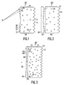
- Figure 1 shows a projection screen 100 usable in, for example, a projection television (PTV) system.
- the rear side of the screen 100 is shaped to form a field lens, which field lens may have a short focal length, comparable to the diagonal size of the screen, typical of projection screens used in compact PTV systems.
- Light comprising the image to be displayed emanates from a projection lens or image source 101.
- the light rays from source 101 are converted to parallel rays by the field lens at the rear side 102 of the screen which is provided with a Fresnel lens structure with facets 103, comprising facet surfaces 104 and riser surfaces 106.
- the screen 100 may additionally contain a screen base 115 having a diffuser 108 with diffuser elements 110 which controls the spread of the light in the vertical direction to an angle of 11°, for example, and a lenticular array 112 containing lenticules 114 that permits efficient wide-angle viewing (a horizontal angle of 170° for example).
- the facets 103 refract light received from the source 110 to form the parallel or collimated rays that impinge upon the diffuser and lenticules.
- the facet surfaces 104 are primarily responsible for refraction in the Fresnel lens structure
- the riser surfaces 106 primarily cause a loss of transmission efficiency of the screen 100 because light impinging on these surfaces is misdirected or lost.
- the facets 103 located at the perimeter of the Fresnel lens structure have larger riser surfaces than the facets 103 towards the center. This is a necessary limitation since the amount of refraction required to convert divergent rays from a small source of light into parallel rays at a given location on the Fresnel lens is directly proportional to the distance from the center of the lens to the given location.
- the riser surfaces 106 are larger near the edges of the Fresnel lens structure, a greater portion of light is misdirected, resulting in decreased luminance near the edges, thus giving the lens a "bright spot" effect in its center.
- the projection screen 200 in Figure 2 eliminates the edge luminance reduction problems of the projection screen 100 in Figure 1 by a separation of its field lens 202, which contains a Fresnel lens structure 204, from the remainder of the screen.
- the Fresnel lens structure 204 converts the rays from the light source into parallel rays just as the Fresnel lens structure at the rear side 102 of the screen shown in Fig. 1.
- the incidents of misdirected light are greatly reduced, so that no "bright spot" appears at the center.
- the projection screen 300 greatly reduces the edge luminance fall-off problem associated with the screen 100, shown in Fig. 1, while avoiding the large transmission efficiency loss penalty associated with the screen 200 shown in Fig. 2 and the number of disturbing artifacts.
- the screen 300 comprises a field lens 308 which contains two Fresnel lens surfaces 302 and 310.
- the field lens 308 is connected with its front surfaces 310 to the rear side of the screen base 315.
- the rear side of the screen base having a surface interlocking with the surface 310 of the field lens 308.
- the rear and front surfaces 302 and 310 of the field lens 308 are separated by a region 309 filled with a medium with an index of refraction (n1) different from that of either the screen base 315 (n2) or the incident medium 301 (n).
- the region 309 is for example filled with U.V. curing polymer having an index of refraction n1 of approximately 1.59.
- the screen base 315 may be of polymethylmethacrylate (PMMA) material with n2 approximately equal to 1.49.
- the presence of the second Fresnel lens surface 310 has the effect of dividing the required optical power of the field lens 308 between the two Fresnel lens surfaces 302 and 310.
- the riser surfaces 306 are smaller than corresponding riser surfaces 106 in Figure 1, resulting in less misdirected light.
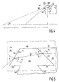
- the facet angles of the two Fresnel lens surfaces 302 and 310 can be calculated as follows, with reference to Figures 4 and 5.
- the optical power of the field lens 308 is evenly divided between surfaces 302 and 310, and the distance across the region 309 between the surfaces 302 and 310 is small and will be neglected in the following calculation. Therefore the optical power of each surface is 1/(2f), where f is the focal length of the field lens 308.
- the facet angle ⁇ of a facet on surface 302 is given by the following equation h being the distance from the optical center of the field lens 308 to the facet, and n1 being the refractive index of region 309.
- a ray incident on facet surface 304 makes an angle ⁇ 1, with the normal, such that
- the angle ⁇ 1′ of the refracted ray is found by using Snell's Law, and assuming the refractive index n of the incident medium 301 is equal to 1.
- facet angles for a one-piece projection screen with an embedded two-sided Fresnel lens as a field lens can be readily calculated.
- the focal length of the field lens is 99 cm (39 inches)
- the diagonal of the screen is 94 cm (37) inches)
- the maximum distance from the optical center to the facet being 47 cm
- n1 and n2 are 1.59 (for Polystyrene) and 1.49 (for PMMA) respectively
- facet surface 304 will have an angle ⁇ of approximately 20° and facet surface 312 will have an angle ⁇ of approximately 62°.
- the number of surfaces to be transferred by the light is reduced by one.
- the difference of the refractive indices of the field lens material and the screen base material is moderate the amount of light lost due to reflection at this surface is greatly reduced relative to the amount of light lost at the surfaces between the field lens 202 and the screen base 206 of the screen 200 shown in Fig. 2.
- the transmission efficiency of the screen according to the invention exceeds that of the screen in Fig. 2 by approximately 8%.
- the projection screen embodying the present invention need not be limited to use in a PTV system, but may be used with other projection systems.
- the optical power of the field lens need not be divided equally between the two surfaces, and may be divided between more than two surfaces with any desired ratio.
- the optical power of the field lens need not be chosen to collimate the rays from the projection lens, but could convert the light from the image source into a less divergent beam or into a convergent beam.
- the composition of the Fresnel lens is not limited to a particular material, and, rather than utilizing rotationally symmetrical Fresnel lenses, the present invention may utilize a field lens comprising cylindrical or linear Fresnel lenses. Such Fresnel lenses eliminate, or greatly reduce, Moiré-interference patterns in the projected image. Also, the present invention is functional even where the optical center of the Fresnel is vertically offset from the optical axis of the PTV display arrangement.
Landscapes
- Physics & Mathematics (AREA)
- General Physics & Mathematics (AREA)
- Engineering & Computer Science (AREA)
- Multimedia (AREA)
- Signal Processing (AREA)
- Overhead Projectors And Projection Screens (AREA)
- Transforming Electric Information Into Light Information (AREA)
Applications Claiming Priority (2)
| Application Number | Priority Date | Filing Date | Title |
|---|---|---|---|
| US07/090,487 US4773731A (en) | 1987-08-28 | 1987-08-28 | One-piece projection screen |
| US90487 | 1987-08-28 |
Publications (3)
| Publication Number | Publication Date |
|---|---|
| EP0305009A2 true EP0305009A2 (fr) | 1989-03-01 |
| EP0305009A3 EP0305009A3 (en) | 1989-09-20 |
| EP0305009B1 EP0305009B1 (fr) | 1993-10-27 |
Family
ID=22222988
Family Applications (1)
| Application Number | Title | Priority Date | Filing Date |
|---|---|---|---|
| EP88201798A Expired - Lifetime EP0305009B1 (fr) | 1987-08-28 | 1988-08-24 | Ecran unitaire de projection |
Country Status (6)
| Country | Link |
|---|---|
| US (1) | US4773731A (fr) |
| EP (1) | EP0305009B1 (fr) |
| JP (1) | JP2904214B2 (fr) |
| KR (1) | KR890004565A (fr) |
| DE (1) | DE3885210T2 (fr) |
| DK (1) | DK171004B1 (fr) |
Cited By (4)
| Publication number | Priority date | Publication date | Assignee | Title |
|---|---|---|---|---|
| EP0457280A2 (fr) * | 1990-05-14 | 1991-11-21 | Canon Kabushiki Kaisha | Ecran et projecteur utilisant celui-ci |
| WO2000042469A1 (fr) * | 1999-01-13 | 2000-07-20 | 3M Innovative Properties Company | Lentille fresnel pour ecrans de projection |
| WO2006032002A1 (fr) * | 2004-09-13 | 2006-03-23 | Fusion Optix, Inc. | Ecran a trajet optique corrige et contraste eleve |
| WO2016082097A1 (fr) * | 2014-11-25 | 2016-06-02 | 博立多媒体控股有限公司 | Système de lentille de fresnel |
Families Citing this family (39)
| Publication number | Priority date | Publication date | Assignee | Title |
|---|---|---|---|---|
| JP2731169B2 (ja) * | 1988-07-18 | 1998-03-25 | 株式会社日立製作所 | 近距離観視用投写形ディスプレイ装置 |
| EP0371432B1 (fr) * | 1988-11-28 | 1995-07-05 | Mitsubishi Rayon Co., Ltd. | Méthode de fabrication d'un écran du type à transmission |
| DE3921061A1 (de) * | 1989-06-23 | 1991-01-03 | Hertz Inst Heinrich | Wiedergabeeinrichtung fuer dreidimensionale wahrnehmung von bildern |
| NL8902112A (nl) * | 1989-08-22 | 1991-03-18 | Philips Nv | Doorzichtprojektiescherm en doorzichtprojektiesysteem voorzien van een dergelijk scherm. |
| JP2625317B2 (ja) * | 1992-06-11 | 1997-07-02 | ミサワホーム株式会社 | ユニット式建物の上下階接合構造 |
| US5457572A (en) * | 1992-12-17 | 1995-10-10 | Kuraray Co., Ltd. | Rear-projection screen |
| US20030206342A1 (en) * | 1993-05-12 | 2003-11-06 | Bright View Technologies, Inc. | Micro-lens array based light transmission screen |
| US6788460B2 (en) * | 1998-04-15 | 2004-09-07 | Duke University | Projection screen apparatus |
| US6483612B2 (en) | 1998-04-15 | 2002-11-19 | Duke University | Projection screen apparatus including holographic optical element |
| US5668662A (en) * | 1994-05-12 | 1997-09-16 | Philips Electronics North America Corporation | Front projection screen with lenticular front surface |
| JP3371654B2 (ja) * | 1995-10-30 | 2003-01-27 | ソニー株式会社 | 投射型ディスプレイ装置 |
| DE69830303T2 (de) * | 1997-12-29 | 2006-02-02 | Koninklijke Philips Electronics N.V. | Rückprojektionsschirm |
| US6163402A (en) | 1998-06-11 | 2000-12-19 | 3M Innovative Properties Company | Rear projection screen |
| US6449089B1 (en) | 1998-03-30 | 2002-09-10 | 3M Innovative Properties Company | Rear projection screen with enhanced contrast |
| US6967779B2 (en) * | 1998-04-15 | 2005-11-22 | Bright View Technologies, Inc. | Micro-lens array with precisely aligned aperture mask and methods of producing same |
| US6829087B2 (en) * | 1998-04-15 | 2004-12-07 | Bright View Technologies, Inc. | Micro-lens array based light transmitting screen with tunable gain |
| US6816306B2 (en) * | 1998-04-15 | 2004-11-09 | Bright View Technologies Inc. | Micro-lens array based light transmitting screen with high resolution and low imaging artifacts |
| DK1218795T3 (da) * | 1999-09-29 | 2003-08-25 | Scan Vision Screen Aps | Translucent skærm omfattende et linsesystem |
| DE10022713B4 (de) * | 2000-05-10 | 2004-02-05 | Osram Opto Semiconductors Gmbh | Signalgeber für Verkehrssignale |
| US20020096859A1 (en) * | 2001-01-22 | 2002-07-25 | Versaw Douglas W. | Motorcycle trailer hitch |
| US6819486B2 (en) | 2001-01-17 | 2004-11-16 | 3M Innovative Properties Company | Projection screen having elongated structures |
| CA2481647A1 (fr) * | 2002-04-12 | 2003-10-23 | Duke University | Ecran de projection |
| US6896375B2 (en) * | 2002-08-16 | 2005-05-24 | Infocus Corporation | Rear projection display device having multiple mirrors that are substantially parallel to a screen |
| US7150537B2 (en) | 2002-08-16 | 2006-12-19 | Infocus Corporation | Projection television device and screen |
| US7102820B2 (en) * | 2002-08-16 | 2006-09-05 | Infocus Corporation | Flat valley fresnel lens for a display device |
| US7777949B2 (en) * | 2002-08-16 | 2010-08-17 | Seiko Epson Corporation | Laminate screen for a display device |
| US7009765B2 (en) * | 2002-08-16 | 2006-03-07 | Infocus Corporation | Wide angle lens system having a distorted intermediate image |
| US7088507B2 (en) * | 2002-08-16 | 2006-08-08 | Infocus Corporation | Rear projection display |
| US7175287B2 (en) * | 2002-08-16 | 2007-02-13 | Infocus Corporation | Wide angle projection lens |
| US7341353B2 (en) * | 2002-08-16 | 2008-03-11 | Infocus Corporation | Variable fresnel screen for use in projection device |
| US7277227B2 (en) * | 2002-09-24 | 2007-10-02 | Dai Nippon Printing Co., Ltd. | Fresnel lens sheet, transmission screen provided with the same and rear projection display |
| US6917469B2 (en) * | 2003-06-27 | 2005-07-12 | Japan Acryace Co., Ltd. | Light diffusing laminated plate |
| KR100553889B1 (ko) * | 2003-07-15 | 2006-02-24 | 삼성전자주식회사 | 프로젝션 표시 장치용 스크린 |
| US7080910B2 (en) * | 2003-08-19 | 2006-07-25 | Infocus Corporation | Method and system for a thermal architecture and user adjustable keystone in a display device |
| US20060181770A1 (en) | 2005-02-15 | 2006-08-17 | K Laser Technology, Inc. | Rear projection screen with spatial varying diffusing angle |
| US9291887B2 (en) | 2011-05-12 | 2016-03-22 | Prysm, Inc. | Rollable display screen quilt |
| US8830577B2 (en) * | 2011-05-12 | 2014-09-09 | Prysm, Inc. | Rollable display screen |
| KR20170092674A (ko) * | 2014-12-10 | 2017-08-11 | 볼리미디어 홀딩즈 컴퍼니 리미티드 | 전자기 복사 감지 시스템 |
| US20180045933A1 (en) * | 2016-06-30 | 2018-02-15 | Danielle Dileo | Optical system for an led wash luminaire |
Citations (7)
| Publication number | Priority date | Publication date | Assignee | Title |
|---|---|---|---|---|
| GB2072376A (en) * | 1980-01-29 | 1981-09-30 | Matsushita Electric Ind Co Ltd | Translucent projection screen |
| JPS58160940A (ja) * | 1982-03-19 | 1983-09-24 | Dainippon Printing Co Ltd | 透過型映写用スクリ−ン板 |
| JPS5988723A (ja) * | 1982-11-12 | 1984-05-22 | Dainippon Printing Co Ltd | レンチキユラ−スクリ−ン |
| EP0118951A1 (fr) * | 1983-03-07 | 1984-09-19 | Koninklijke Philips Electronics N.V. | Ecran de projection |
| JPS6190149A (ja) * | 1984-10-09 | 1986-05-08 | Hitachi Ltd | 透過形スクリ−ン |
| EP0233662A1 (fr) * | 1986-01-28 | 1987-08-26 | Koninklijke Philips Electronics N.V. | Système à projection arrière |
| JPS632031A (ja) * | 1986-06-23 | 1988-01-07 | Mitsubishi Rayon Co Ltd | 透過型スクリ−ン |
Family Cites Families (2)
| Publication number | Priority date | Publication date | Assignee | Title |
|---|---|---|---|---|
| JPS5189419A (fr) * | 1975-02-03 | 1976-08-05 | ||
| US4679900A (en) * | 1986-06-05 | 1987-07-14 | North American Philips Corporation | Bulk diffuser for a projection television screen |
-
1987
- 1987-08-28 US US07/090,487 patent/US4773731A/en not_active Expired - Lifetime
-
1988
- 1988-08-24 DE DE88201798T patent/DE3885210T2/de not_active Expired - Fee Related
- 1988-08-24 EP EP88201798A patent/EP0305009B1/fr not_active Expired - Lifetime
- 1988-08-25 KR KR1019880010805A patent/KR890004565A/ko not_active Application Discontinuation
- 1988-08-25 DK DK474088A patent/DK171004B1/da not_active IP Right Cessation
- 1988-08-25 JP JP63209595A patent/JP2904214B2/ja not_active Expired - Fee Related
Patent Citations (7)
| Publication number | Priority date | Publication date | Assignee | Title |
|---|---|---|---|---|
| GB2072376A (en) * | 1980-01-29 | 1981-09-30 | Matsushita Electric Ind Co Ltd | Translucent projection screen |
| JPS58160940A (ja) * | 1982-03-19 | 1983-09-24 | Dainippon Printing Co Ltd | 透過型映写用スクリ−ン板 |
| JPS5988723A (ja) * | 1982-11-12 | 1984-05-22 | Dainippon Printing Co Ltd | レンチキユラ−スクリ−ン |
| EP0118951A1 (fr) * | 1983-03-07 | 1984-09-19 | Koninklijke Philips Electronics N.V. | Ecran de projection |
| JPS6190149A (ja) * | 1984-10-09 | 1986-05-08 | Hitachi Ltd | 透過形スクリ−ン |
| EP0233662A1 (fr) * | 1986-01-28 | 1987-08-26 | Koninklijke Philips Electronics N.V. | Système à projection arrière |
| JPS632031A (ja) * | 1986-06-23 | 1988-01-07 | Mitsubishi Rayon Co Ltd | 透過型スクリ−ン |
Non-Patent Citations (4)
| Title |
|---|
| PATENT ABSTRACTS OF JAPAN vol. 007, no. 286 (P-244) <1431> 21 December 1983 & JP 58 160940 A (DAINIPPON) 24 September 1983 * |
| PATENT ABSTRACTS OF JAPAN vol. 008, no. 204 (P-301) <1641> 18 September 1984 & JP 59 088723 A (DAINIPPON) 22 May 1984 * |
| PATENT ABSTRACTS OF JAPAN vol. 010, no. 264 (P-495) <2320> 09 September 1986 & JP 61 090149 A (HITACHI) 08 May 1986 * |
| PATENT ABSTRACTS OF JAPAN vol. 012, no. 199 (P-714) <3046> 09 June 1988 & JP 63 002031 A (MITSUBISHI) 07 January 1988 * |
Cited By (11)
| Publication number | Priority date | Publication date | Assignee | Title |
|---|---|---|---|---|
| EP0457280A2 (fr) * | 1990-05-14 | 1991-11-21 | Canon Kabushiki Kaisha | Ecran et projecteur utilisant celui-ci |
| EP0457280B1 (fr) * | 1990-05-14 | 1999-08-11 | Canon Kabushiki Kaisha | Ecran et système de projection utilisant celui-ci |
| WO2000042469A1 (fr) * | 1999-01-13 | 2000-07-20 | 3M Innovative Properties Company | Lentille fresnel pour ecrans de projection |
| US6407859B1 (en) | 1999-01-13 | 2002-06-18 | 3M Innovative Properties Company | Fresnel lens for projection screen |
| US6710941B2 (en) | 1999-01-13 | 2004-03-23 | 3M Innovative Properties Company | Fresnel lens for projection screens |
| WO2006032002A1 (fr) * | 2004-09-13 | 2006-03-23 | Fusion Optix, Inc. | Ecran a trajet optique corrige et contraste eleve |
| WO2016082097A1 (fr) * | 2014-11-25 | 2016-06-02 | 博立多媒体控股有限公司 | Système de lentille de fresnel |
| GB2548756A (en) * | 2014-11-25 | 2017-09-27 | Bolymedia Holdings Co Ltd | Fresnel lens system |
| AU2014412625B2 (en) * | 2014-11-25 | 2018-05-17 | Bolymedia Holdings Co. Ltd. | Fresnel lens system |
| US10203432B2 (en) | 2014-11-25 | 2019-02-12 | Bolymedia Holdings Co. Ltd. | Fresnel lens system |
| GB2548756B (en) * | 2014-11-25 | 2021-04-21 | Bolymedia Holdings Co Ltd | Fresnel lens system |
Also Published As
| Publication number | Publication date |
|---|---|
| EP0305009A3 (en) | 1989-09-20 |
| JP2904214B2 (ja) | 1999-06-14 |
| DE3885210D1 (de) | 1993-12-02 |
| DK474088A (da) | 1989-03-01 |
| EP0305009B1 (fr) | 1993-10-27 |
| JPS6472135A (en) | 1989-03-17 |
| DK171004B1 (da) | 1996-04-15 |
| DK474088D0 (da) | 1988-08-25 |
| KR890004565A (ko) | 1989-04-22 |
| DE3885210T2 (de) | 1994-05-05 |
| US4773731A (en) | 1988-09-27 |
Similar Documents
| Publication | Publication Date | Title |
|---|---|---|
| EP0305009B1 (fr) | Ecran unitaire de projection | |
| US4767186A (en) | Front projection screen with rear light concentrating lens array | |
| KR940006725B1 (ko) | 배면 투사 스크린 | |
| US4708435A (en) | Rear projection screen | |
| US6157491A (en) | Lenticular lens sheet | |
| JP2596917B2 (ja) | 情報表示装置 | |
| EP0511721A2 (fr) | Ecran de projection par réflection avec un réseau de lentilles pour concentrer la lumière réfléchie | |
| US4762393A (en) | Rear projection screen and rear projection system provided with such a screen | |
| KR100229971B1 (ko) | 후방투영 스크린 | |
| US6782178B2 (en) | Planar optical waveguides for optical panel having gradient refractive index core | |
| EP0260758A2 (fr) | Ecran à uniformité avancée de luminance pour projection par transparence | |
| CA2395238A1 (fr) | Systeme optique pour panneau d'affichage | |
| EP0240045A1 (fr) | Système de projection compacte avec un faisceau de lumière d'incidence oblique | |
| JP2004505290A (ja) | 黒色鋸歯状光学パネル | |
| CA2375417A1 (fr) | Ecran de projection a lentilles lenticulaires de puissances optiques differentes | |
| US4824227A (en) | Optimum riser angle for fresnel lenses in projection screens | |
| EP1280003A1 (fr) | Ecran de projection orthogonale | |
| US4118114A (en) | Low-glare overhead projector | |
| US5071224A (en) | Lenticular lens for use in back projection type television receiver | |
| US7342728B2 (en) | Fresnel lens, backprojection screen, and corresponding backprojection system and unit | |
| JPH0480370B2 (fr) | ||
| JP2742780B2 (ja) | 透過型プリズムスクリーン及び投影システム | |
| Bradley et al. | Ultra-wide viewing angle rear projection television screen | |
| KR970010764B1 (ko) | 프러젝션 tv의 스크린용 렌티큘러렌즈 | |
| JPH07119927B2 (ja) | 透過型スクリ−ン |
Legal Events
| Date | Code | Title | Description |
|---|---|---|---|
| PUAI | Public reference made under article 153(3) epc to a published international application that has entered the european phase |
Free format text: ORIGINAL CODE: 0009012 |
|
| AK | Designated contracting states |
Kind code of ref document: A2 Designated state(s): DE FR GB IT |
|
| PUAL | Search report despatched |
Free format text: ORIGINAL CODE: 0009013 |
|
| AK | Designated contracting states |
Kind code of ref document: A3 Designated state(s): DE FR GB IT |
|
| 17P | Request for examination filed |
Effective date: 19900316 |
|
| 17Q | First examination report despatched |
Effective date: 19920316 |
|
| GRAA | (expected) grant |
Free format text: ORIGINAL CODE: 0009210 |
|
| AK | Designated contracting states |
Kind code of ref document: B1 Designated state(s): DE FR GB IT |
|
| REF | Corresponds to: |
Ref document number: 3885210 Country of ref document: DE Date of ref document: 19931202 |
|
| ITF | It: translation for a ep patent filed |
Owner name: ING. C. GREGORJ S.P.A. |
|
| ET | Fr: translation filed | ||
| PLBE | No opposition filed within time limit |
Free format text: ORIGINAL CODE: 0009261 |
|
| STAA | Information on the status of an ep patent application or granted ep patent |
Free format text: STATUS: NO OPPOSITION FILED WITHIN TIME LIMIT |
|
| 26N | No opposition filed | ||
| REG | Reference to a national code |
Ref country code: FR Ref legal event code: CD |
|
| REG | Reference to a national code |
Ref country code: FR Ref legal event code: CD |
|
| REG | Reference to a national code |
Ref country code: GB Ref legal event code: IF02 |
|
| PGFP | Annual fee paid to national office [announced via postgrant information from national office to epo] |
Ref country code: GB Payment date: 20040826 Year of fee payment: 17 |
|
| PGFP | Annual fee paid to national office [announced via postgrant information from national office to epo] |
Ref country code: FR Payment date: 20040830 Year of fee payment: 17 |
|
| PGFP | Annual fee paid to national office [announced via postgrant information from national office to epo] |
Ref country code: DE Payment date: 20041015 Year of fee payment: 17 |
|
| REG | Reference to a national code |
Ref country code: GB Ref legal event code: 746 Effective date: 20050518 |
|
| REG | Reference to a national code |
Ref country code: FR Ref legal event code: D6 |
|
| PG25 | Lapsed in a contracting state [announced via postgrant information from national office to epo] |
Ref country code: IT Free format text: LAPSE BECAUSE OF NON-PAYMENT OF DUE FEES Effective date: 20050824 Ref country code: GB Free format text: LAPSE BECAUSE OF NON-PAYMENT OF DUE FEES Effective date: 20050824 |
|
| PG25 | Lapsed in a contracting state [announced via postgrant information from national office to epo] |
Ref country code: DE Free format text: LAPSE BECAUSE OF NON-PAYMENT OF DUE FEES Effective date: 20060301 |
|
| GBPC | Gb: european patent ceased through non-payment of renewal fee |
Effective date: 20050824 |
|
| PG25 | Lapsed in a contracting state [announced via postgrant information from national office to epo] |
Ref country code: FR Free format text: LAPSE BECAUSE OF NON-PAYMENT OF DUE FEES Effective date: 20060428 |
|
| REG | Reference to a national code |
Ref country code: FR Ref legal event code: ST Effective date: 20060428 |