EP0304827A1 - Power regulation for a combined plant - Google Patents
Power regulation for a combined plant Download PDFInfo
- Publication number
- EP0304827A1 EP0304827A1 EP88113546A EP88113546A EP0304827A1 EP 0304827 A1 EP0304827 A1 EP 0304827A1 EP 88113546 A EP88113546 A EP 88113546A EP 88113546 A EP88113546 A EP 88113546A EP 0304827 A1 EP0304827 A1 EP 0304827A1
- Authority
- EP
- European Patent Office
- Prior art keywords
- steam
- compressor
- turbine
- steam turbine
- preheating
- Prior art date
- Legal status (The legal status is an assumption and is not a legal conclusion. Google has not performed a legal analysis and makes no representation as to the accuracy of the status listed.)
- Granted
Links
Images

Classifications
-
- F—MECHANICAL ENGINEERING; LIGHTING; HEATING; WEAPONS; BLASTING
- F02—COMBUSTION ENGINES; HOT-GAS OR COMBUSTION-PRODUCT ENGINE PLANTS
- F02C—GAS-TURBINE PLANTS; AIR INTAKES FOR JET-PROPULSION PLANTS; CONTROLLING FUEL SUPPLY IN AIR-BREATHING JET-PROPULSION PLANTS
- F02C9/00—Controlling gas-turbine plants; Controlling fuel supply in air- breathing jet-propulsion plants
- F02C9/48—Control of fuel supply conjointly with another control of the plant
- F02C9/50—Control of fuel supply conjointly with another control of the plant with control of working fluid flow
- F02C9/54—Control of fuel supply conjointly with another control of the plant with control of working fluid flow by throttling the working fluid, by adjusting vanes
-
- F—MECHANICAL ENGINEERING; LIGHTING; HEATING; WEAPONS; BLASTING
- F01—MACHINES OR ENGINES IN GENERAL; ENGINE PLANTS IN GENERAL; STEAM ENGINES
- F01K—STEAM ENGINE PLANTS; STEAM ACCUMULATORS; ENGINE PLANTS NOT OTHERWISE PROVIDED FOR; ENGINES USING SPECIAL WORKING FLUIDS OR CYCLES
- F01K23/00—Plants characterised by more than one engine delivering power external to the plant, the engines being driven by different fluids
- F01K23/02—Plants characterised by more than one engine delivering power external to the plant, the engines being driven by different fluids the engine cycles being thermally coupled
- F01K23/06—Plants characterised by more than one engine delivering power external to the plant, the engines being driven by different fluids the engine cycles being thermally coupled combustion heat from one cycle heating the fluid in another cycle
- F01K23/10—Plants characterised by more than one engine delivering power external to the plant, the engines being driven by different fluids the engine cycles being thermally coupled combustion heat from one cycle heating the fluid in another cycle with exhaust fluid of one cycle heating the fluid in another cycle
- F01K23/101—Regulating means specially adapted therefor
-
- F—MECHANICAL ENGINEERING; LIGHTING; HEATING; WEAPONS; BLASTING
- F02—COMBUSTION ENGINES; HOT-GAS OR COMBUSTION-PRODUCT ENGINE PLANTS
- F02C—GAS-TURBINE PLANTS; AIR INTAKES FOR JET-PROPULSION PLANTS; CONTROLLING FUEL SUPPLY IN AIR-BREATHING JET-PROPULSION PLANTS
- F02C7/00—Features, components parts, details or accessories, not provided for in, or of interest apart form groups F02C1/00 - F02C6/00; Air intakes for jet-propulsion plants
- F02C7/08—Heating air supply before combustion, e.g. by exhaust gases
-
- Y—GENERAL TAGGING OF NEW TECHNOLOGICAL DEVELOPMENTS; GENERAL TAGGING OF CROSS-SECTIONAL TECHNOLOGIES SPANNING OVER SEVERAL SECTIONS OF THE IPC; TECHNICAL SUBJECTS COVERED BY FORMER USPC CROSS-REFERENCE ART COLLECTIONS [XRACs] AND DIGESTS
- Y02—TECHNOLOGIES OR APPLICATIONS FOR MITIGATION OR ADAPTATION AGAINST CLIMATE CHANGE
- Y02E—REDUCTION OF GREENHOUSE GAS [GHG] EMISSIONS, RELATED TO ENERGY GENERATION, TRANSMISSION OR DISTRIBUTION
- Y02E20/00—Combustion technologies with mitigation potential
- Y02E20/16—Combined cycle power plant [CCPP], or combined cycle gas turbine [CCGT]
- Y02E20/18—Integrated gasification combined cycle [IGCC], e.g. combined with carbon capture and storage [CCS]
Definitions
- the invention relates to the power control of a combined gas / steam turbine power plant, essentially consisting of at least one gas turbine group, a heat recovery steam generator, a steam turbine, a generator and a condenser.
- waste heat steam generator waste heat boiler
- this part-load operation can take place via the fuel regulation by reducing the fuel flow, but at almost constant permanent air flow, the turbine inlet temperature is lowered.
- this type of power control also reaches its limits: at a partial load of 80%, the temperature of the turbine exhaust gases rises to the still permissible maximum value due to the adjustment of the compressor guide vanes; A further reduction in the partial load by adjusting the compressor guide vanes is not recommended in terms of system technology and in the light of the efficiencies that can be achieved with it.
- the invention seeks to remedy this.
- the invention is based on the object of proposing a power control in a combined gas / steam turbine power plant of the type mentioned, in which the load can be reduced to less than 70% with minimal loss of efficiency.
- Preheating the air drawn in by the compressor is suitable for reducing the mass flow rate through the gas turbine, which allows a corresponding reduction in the amount of fuel without the permissible gas temperature falling at the inlet to the turbine. This also results in a very good partial load efficiency for a combination system, provided that the preheating of the compressor air does not use heat that could have been used for steam or electricity production.
- the great advantage of the invention can be seen in the fact that steam is removed from the steam turbine for preheating the compressor air, specifically at a location where the exergetic potential of the steam removed there is only slightly to used up, and consequently the specific electrical output of the steam turbine System is trimmed very weakly. On average, it can be expected that the specific output of the steam turbine will only drop by 1/10 of the energy used for preheating due to this steam extraction.
- Fig. 1 shows the interaction of a combination plant, which consists essentially of a gas turbine group and a steam turbine cycle.
- the non-visible provision of the fuel required to operate the combustion chamber 4 and possibly the waste heat boiler 7 can be accomplished, for example, by coal gasification integrated in the combination system.
- the gas turbine group 1 as an autonomous unit consists of a compressor 2, a gas turbine 3 coupled to it, a combustion chamber 4; There is a connection to a generator 5.
- the sucked-in air 18 is compressed in the compressor 2 and flows via a line as compressed air 20 into the combustion chamber 4.
- the air which has been converted into hot gas 21 in the combustion chamber 4 then acts on the gas turbine 3.
- the gas turbine exhaust gases 22 become consequently no longer blown off, but instead they flow through a waste heat boiler 7, in which the steam generation for the application of a downstream steam turbine 6 is provided by heat exchange.
- the waste heat boiler 7 shown is a two-pressure waste heat boiler.
- an impression waste heat boiler can also be used.
- the latter has the advantage over this that the temperature of the flue gases 29 can be lowered lower, which increases the efficiency of the combination system.
- an additional furnace (not shown) can be added to the waste heat boiler 7, which processes the gas turbine exhaust gases 22 to a higher temperature level.
- the latter arrangement proves to be advantageous if the power output of the combination system has to be increased during load peaks. It is also possible to use a three-pressure waste heat boiler.
- the thermal energy of the gas turbine exhaust gases 22 is therefore mainly used to generate high and low pressure steam 24 which acts on the steam turbine 6. This is advantageously coupled to the same generator 5 of the turbo group 1.
- the potential of the gas turbine exhaust gases 22 can be optimally exploited in such a way that these exhaust gases, which at the end of the Gas turbine process still have a temperature of about 500 ° C, so that can be lowered to about 100 ° C.
- the relaxed steam then flows after leaving the steam turbine 6 into the condenser 9, water or air being able to be used here as the cooling medium. Conveyed by a pump 10, the condensate 23 usually flows into a preheater, not shown, and from here into a feed water tank and degasser, also not shown.
- the condensate After passing through these stages, the condensate is processed to such an extent that it can be returned to the waste heat boiler 7 for renewed evaporation.
- Steam 25 is removed from the steam turbine 6 and sent through a heat exchanger 8, in which the intake air 18 to the compressor 2 of the gas turbine group 1 is mentioned in the heat exchange process. After passing through the heat exchanger 8, the steam, which has now been converted to condensate, is returned to the treatment process via the pump 10.
- a controller 13 takes over the necessary interventions for regulating the power of the combination system.
- the inlet and outlet temperatures 14, 15 of the gas turbine 3 are preferably supplied to the preprogrammed controller 13 as information carriers.
- the controller 13 can thus be preprogrammed for a power control tailored to the respective system, but of course only those controls that come into question guarantee the lowest loss of efficiency, ie allow the greatest possible throttling of the fuel quantity via signal 32 and valve 33 without the permissible turbine inlet temperature dropping.
- the speed can also be regulated.
- the capacity control of the system can either be done by simply adjusting the compressor guide vanes, or by preheating the Intake air 18 to the compressor 2, or also by a combination and control cascade.
- the control cascade is characterized in that an initial adjustment of the compressor guide vanes is preferably followed by preheating the intake air 18. If the system has to be run at partial load by means of a control cascade, a servo motor 12 used to adjust the compressor guide vanes receives a command from the controller 13 to act on the guide vanes. It is entirely sufficient if this adjustment is limited to the preliminary line of the compressor 2. This process is monitored by the controller 13 by continuously calling up the gas temperatures before (14) and after (15) the gas turbine 3.
- a second control stage intervenes, which now continues the power reduction to the compressor 2 by preheating the intake air 18.
- a control valve 11 placed in the steam extraction line 25 downstream of the heat exchanger 8 opens by command 17, so that the vapor flow through the heat exchanger 8 can take place.
- the degree of opening of the valve 11 will only allow water to pass through.
- the steam extraction 25 required for this purpose is carried out at a point 19 of the steam turbine 6, where the exergetic potential of the steam is only slightly to used up.
- Curve 26 shows the course of the thermal efficiency in the case of power regulation by means of pure fuel regulation.
- the course of this curve shows quite clearly how the thermal efficiency decreases rapidly during part-load operation.
- a partial load of the combi system of 70% it is only approx. 44%. Operation at partial load is not uncommon in a combination system, and such operation can also extend over a longer period of time. For this very reason, the efficiency to be achieved is often taken as the basis for partial load operation of 75% and below.
- the further curve 27 shows the course of the thermal efficiency through a power control by preheating the intake air to the compressor. It is unmistakable that the efficiency scores significantly better than the previously discussed type of power control.
- the preheating By limiting the preheating to a maximum of 60 ° C - at an outlet temperature of 15 ° C (ISO) - at the compressor inlet, the performance of the combination system can be regulated down to approx. 75% with minimal loss of efficiency. It can be said that with this preheating the permissible increase in the exhaust gas temperature at the gas turbine outlet has not yet been fully utilized, perhaps by around half, for the sake of estimation. Further preheating above about 60 ° C before the compressor is normally not permitted.
- a further reduction in performance down to 67% with a good efficiency curve could, however, be achieved by adjusting the compressor guide vanes, i.e. from a partial load of 75%, the further reduction could be carried out by adjusting the compressor guide vanes.
- the adjustment of the compressor guide vanes results in a somewhat better efficiency than the preheating of the compressor intake air, it is logical to start with the first-mentioned type of control and then to have the type of control intervene by preheating the compressor intake air.
Abstract
Description
Die Erfindung betrifft die Leistungsregelung einer kombinierten Gas-/Dampfturbinen-Kraftwerksanlage, im wesentlichen bestehend aus mindestens einer Gasturbinengruppe, einem Abhitzedampferzeuger, einer Dampfturbine, einem Generator und einem Kondensator.The invention relates to the power control of a combined gas / steam turbine power plant, essentially consisting of at least one gas turbine group, a heat recovery steam generator, a steam turbine, a generator and a condenser.
Unter dem Begriff "Kombinierte Gas-/Dampfturbinen-Kraftwerksanlage" - im folgenden Kombianlage genannt - ist immer das Zusammenwirken einer Gasturbogruppe mit mindestens einem Dampfturbinenkreislauf zu verstehen, wobei die Gasturbinenabgase durch einen Abhitzedampferzeuger (= Abhitzekessel) geleitet werden, in welchem das Restwärmepotential dieser Abgase zur Erzeugung des für die Beaufschlagung der Dampfturbine benötigten Dampfes herangezogen wird. Diese zusätzliche Dampfleistung führt zu einem höheren thermischen Wirkungsgrad der Anlage.The term "combined gas / steam turbine power plant" - hereinafter referred to as a combined system - always means the interaction of a gas turbine group with at least one steam turbine cycle, the gas turbine exhaust gases being passed through a waste heat steam generator (= waste heat boiler) in which the residual heat potential of these exhaust gases is used to generate the steam required for the application of the steam turbine. This additional steam output leads to a higher thermal efficiency of the system.
Bei reduzierter benötigter Leistung kann dieser Teillastbetrieb über die Brennstoffregulierung geschehen, indem durch Verminderung des Brennstoffstromes, aber bei nahezu konstant bleibendem Luftstrom, die Turbineneintrittstemperatur abgesenkt wird.If the required power is reduced, this part-load operation can take place via the fuel regulation by reducing the fuel flow, but at almost constant permanent air flow, the turbine inlet temperature is lowered.
Diese an sich einfache Erstellung eines Teillastbetriebes bei solchen Anlagen erweist sich hinsichtlich Wirkungsgradeinbusse als zu wenig attraktiv, sinkt doch der Wirkungsgrad beinahe direkt proportional zur Leistungsreduktion ab. Arbeitet nämlich die Anlage bei Vollastbetrieb mit einem thermischen Wirkungsgrad von ca. 50 %, so erreicht sie bei einem 60 %-igen Teillastbetrieb nur noch einen thermischen Wirkungsgrad von bloss ca. 42 %. Auf dem Weg diese relativ hohe Wirkungsgradeinbusse in engeren Grenzen zu halten, wird bei modernen Kombianlagen die Leistungsabsenkung zusätzlich über eine Verstellung der Verdichterleitschaufeln vorgenommen. Bei dieser Regelung erfährt der thermische Wirkungsgrad eine kleinere Einbusse, Grössenordnung bis ca. 2 Prozentpunkte, indessen kann der Massendurchsatz und damit die Leistung nur bis auf ca. 80 % gesenkt werden. Die Grenze des so praktizierten Regelbereichs, eben 100 - 80 %, ist durch den starken Anstieg der Turbinenaustrittstemperatur begrenzt, welche die Folge des bei möglichst konstant hoher Turbineneintrittstemperatur sinkenden Druckverhältnisses ist.This simple creation of a partial load operation in such systems proves to be too unattractive in terms of efficiency losses, since the efficiency drops almost directly in proportion to the power reduction. If the system operates at full load with a thermal efficiency of approx. 50%, it only achieves a thermal efficiency of only approx. 42% with 60% partial load operation. On the way to keeping this relatively high loss in efficiency within narrow limits, the power in modern combi systems is additionally reduced by adjusting the compressor guide vanes. With this regulation, the thermal efficiency experiences a smaller loss, in the order of magnitude up to approx. 2 percentage points, but the mass throughput and thus the output can only be reduced to approx. 80%. The limit of the control range practiced in this way, namely 100-80%, is limited by the sharp rise in the turbine outlet temperature, which is the result of the pressure ratio decreasing while the turbine inlet temperature is as high as possible.
Somit stösst auch diese Art von Leistungsregelung an Grenzen: Bei einer Teillast von 80 % steigt durch die Verstellung der Verdichterleitschaufeln die Temperatur der Turbinenabgase auf den noch zulässigen Höchstwert an; eine weitere Reduzierung der Teillast durch Verstellung der Verdichterleitschaufeln ist anlagetechnisch und im Lichte der damit erzielbaren Wirkungsgrade nicht empfehlenswert.This means that this type of power control also reaches its limits: at a partial load of 80%, the temperature of the turbine exhaust gases rises to the still permissible maximum value due to the adjustment of the compressor guide vanes; A further reduction in the partial load by adjusting the compressor guide vanes is not recommended in terms of system technology and in the light of the efficiencies that can be achieved with it.
Peilt man demnach tiefere Teillastwerte an, so müsste der Betrieb ab einer Teillast von 80 % wiederum über eine reine Brennstoffregulierung geschehen, dies dann allerdings unter Inkaufnahme der bereits erwähnten Nachteile.If one therefore aims at lower partial load values, operation from a partial load of 80% would again have to be carried out by means of a pure fuel regulation, but this would have to be done with the disadvantages already mentioned.
Hier will die Erfindung Abhilfe schaffen. Der Erfindung, wie sie in den Ansprüchen gekennzeichnet ist, liegt die Aufgabe zugrunde, bei einer kombinierten Gas-/Dampfturbinen-Kraftwerksanlage der eingangs genannten Art eine Leistungsregelung vorzuschlagen, bei welcher die Last unter minimalster Wirkungsgradeinbusse auf unter 70 % abgesenkt werden kann.The invention seeks to remedy this. The invention, as characterized in the claims, is based on the object of proposing a power control in a combined gas / steam turbine power plant of the type mentioned, in which the load can be reduced to less than 70% with minimal loss of efficiency.
Eine Vorerwärmung der vom Verdichter angesaugten Luft ist geeignet, den Massendurchsatz durch die Gasturbine zu vermindern, was eine entsprechende Reduktion der Brennstoffmenge erlaubt, ohne dass die zulässige Gastemperatur am Eintritt in die Turbine absinkt. Dies ergibt auch für eine Kombianlage einen sehr guten Teillastwirkungsgrad, sofern für die Vorerwärmung der Verdichterluft nicht Wärme verwendet wird, welche für die Dampf- bzw. Stromproduktion hätte verwendet werden können.Preheating the air drawn in by the compressor is suitable for reducing the mass flow rate through the gas turbine, which allows a corresponding reduction in the amount of fuel without the permissible gas temperature falling at the inlet to the turbine. This also results in a very good partial load efficiency for a combination system, provided that the preheating of the compressor air does not use heat that could have been used for steam or electricity production.
Der grosse Vorteil der Erfindung ist darin zu sehen, dass für die Vorerwärmung der Verdichterluft Dampf aus der Dampfturbine entnommen wird, und zwar an einem Ort, wo das exergetische Potential des dort entnommenen Dampfes nur noch gering bis aufgebraucht ist, mithin die spezifische elektrische Leistung der Anlage ganz schwach beschnitten wird. Im Schnitt ist zu erwarten, dass die spezifische Leistung der Dampfturbine durch diese Dampfentnahme bloss um 1/10 der entnommenen, der Vorwärmung dienenden Energie abfällt.The great advantage of the invention can be seen in the fact that steam is removed from the steam turbine for preheating the compressor air, specifically at a location where the exergetic potential of the steam removed there is only slightly to used up, and consequently the specific electrical output of the steam turbine System is trimmed very weakly. On average, it can be expected that the specific output of the steam turbine will only drop by 1/10 of the energy used for preheating due to this steam extraction.
Hierbei zeigt es sich, dass durch Begrenzung der Vorerwärmung am Verdichtereintritt, ausgehend von einer Temperatur von 15 °C (ISO), auf maximal 60 °C die Leistung der Kombianlage ohne nennenswerte Wirkungsgradeinbusse auf ca. 75 % hinunter geregelt werden kann. Da damit nur etwa die Hälfte des zulässigen Temperaturanstieges am Turbinenaustritt ausgenützt wird, könnte die Leistung der Kombianlage an sich mit einer vertretbaren Wirkungsgradeinbusse durch Verstellung der Verdichter leitschaufeln noch weiter, bis auf ca. 67 % hinunter geregelt werden.This shows that by limiting the preheating at the compressor inlet, starting from a temperature of 15 ° C (ISO), to a maximum of 60 ° C, the performance of the combination system can be regulated down to approx. 75% without any significant loss in efficiency. Since only about half of the permissible temperature rise at the turbine outlet is thus used, the performance of the combination system itself could be reduced with an acceptable level of efficiency by adjusting the compressor guide vanes even further down to about 67%.
Da aber die Verstellung der Verdichterleitschaufeln bei hoher Teillast einen besseren Wirkungsgrad gegenüber der Vorwärmung der Verdichterluft im gleichen Teillastbereich ergibt, wird man mit Vorteil zuerst von z.B. 100 % auf ca. 90 % (halber möglicher Regelbereich) mit der Leistungsregelung nach Verdichterleitschaufelverstellung operieren, anschliessend, von 90 % bis auf ca. 67 % durch Vorerwärmung der Ansaugluft zum Verdichter weiter regeln.However, since the adjustment of the compressor guide vanes at high partial load results in a better efficiency compared to the preheating of the compressor air in the same partial load range, it is advantageous to use e.g. Operate 100% to approx. 90% (half possible control range) with the power control after compressor guide vane adjustment, then continue to regulate from 90% to approx. 67% by preheating the intake air to the compressor.
Mit dieser kombinierten Regelungsart, auch Regelungskaskade genannt, wird sich, ausgehend von einem thermischen Wirkungsgrad der Kombianlage von ca. 50 % bei Vollast, bei einer Teillast von 67 % noch ein Wirkungsgrad von 47,5 - 48 % einstellen. Dieser hohe Teillastwirkungsgrad der vorliegenden Anlage wird nicht bloss bei reiner Stromerzeugung erreicht, sondern auch bei Wärme-Kraft-Kopplung.With this combined control type, also called control cascade, an efficiency of 47.5 - 48% will still be achieved at a partial load of 67%, based on a thermal efficiency of the combi system of approx. 50% at full load. This high part-load efficiency of the present system is not only achieved with pure electricity generation, but also with cogeneration.
Vorteilhafte und zweckmässige Weiterbildungen der erfindungsgemässen Aufgabenlösung sind in den abhängigen Ansprüchen gekennzeichnet.Advantageous and expedient developments of the task solution according to the invention are characterized in the dependent claims.
Im folgenden wird anhand der Zeichnung ein Ausführungsbeispiel der Erfindung erläutert. Alle für das unmittelbare Verständnis der Erfindung nicht erforderlichen Elemente sind fortgelassen.In the following an embodiment of the invention will be explained with reference to the drawing. All elements not necessary for the immediate understanding of the invention have been omitted.
Es zeigt:
- Fig. 1 ein Kreislaufschema einer Kombianlage mit der Regelungskaskade Verdichterleitschaufelverstellung-Verdichteransaugluftvorerwärmung und
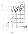
- Fig. 2 das typische Wirkungsgradverhalten verschiedener Teillastregelungsarten.
- Fig. 1 is a circuit diagram of a combination system with the control cascade compressor vane adjustment-compressor intake air preheating and
- Fig. 2 shows the typical efficiency behavior of different partial load control types.
Fig. 1 zeigt das Zusammenwirken einer Kombianlage, die im wesentlichen aus einer Gasturbogruppe und einem Dampfturbinenkreislauf besteht. Die nicht ersichtliche Bereitstellung des zum Betrieb der Brennkammer 4 und allenfalls des Abhitzekessels 7 notwendigen Brennstoffes kann beispielsweise durch eine in die Kombianlage integrierte Kohlevergasung bewerkstelligt werden. Die Gasturbogruppe 1 als autonome Einheit besteht aus einem Verdichter 2, einer mit ihm gekoppelten Gasturbine 3, einer Brennkammer 4; Anschluss besteht zu einem Generator 5. Die angesaugte Luft 18 wird im Verdichter 2 komprimiert und strömt über eine Leitung als verdichtete Luft 20 in die Brennkammer 4. Die in der Brennkammer 4 zu Heissgas 21 aufbereitete Luft beaufschlagt dann die Gasturbine 3. Die Gasturbinenabgase 22 werden nun folgerichtig nicht mehr abgeblasen, sondern sie strömen durch einen Abhitzekessel 7, in welchem durch Wärmeaustausch die Dampferzeugung für die Beaufschlagung einer nachgeschalteten Dampfturbine 6 bereitgestellt wird. Beim dargestellten Abhitzekessel 7 handelt es sich um einen Zweidruck-Abhitzekessel. Selbstverständlich kann auch ein Eindruck-Abhitzekessel eingesetzt werden. Jener hat aber gegenüber diesem den Vorteil, dass die Temperatur der Rauchgase 29 tiefer abgesenkt werden kann, womit der Wirkungsgrad der Kombianlage gesteigert wird. Wahlweise kann dem Abhitzekessel 7 eine nicht dargestellte Zusatzfeuerung beigegeben werden, welche die Gasturbinenabgase 22 auf ein höheres Temperaturniveau aufbereitet. Die letztgenannte Vorkehrung erweist sich dann als vorteilhaft, wenn bei Lastspitzen die Stromleistung der Kombianlage zu steigern ist. Möglich ist ferner auch der Einsatz eines Dreidruck-Abhitzekessels. Aus der thermischen Energie der Gasturbinenabgase 22 wird also vorwiegend Hoch- und Niederdruckdampf 24 erzeugt, der die Dampfturbine 6 beaufschlagt. Diese wird vorteilhaft an den gleichen Generator 5 der Turbogruppe 1 gekoppelt. Durch die Erzeugung von zwei Dampfdrücken lässt sich das Potential der Gasturbinenabgase 22 optimal ausnützen, dergestalt, dass diese Abgase, die am Ende des Gasturbinenprozesses noch eine Temperatur von ca. 500 °C aufweisen, damit bis auf ca. 100 °C abgesenkt werden können. Der entspannte Dampf strömt nach Verlassen der Dampfturbine 6 dann in den Kondensator 9, wobei hier als Abkühlungsmedium Wasser oder Luft zum Einsatz gelangen kann. Durch eine Pumpe 10 gefördert, strömt das Kondensat 23 üblicherweise in einen nicht dargestellten Vorwärmer und von hier aus in einen ebenfalls nicht gezeigten Speisewasserbehälter und Entgaser. Nach Durchlauf dieser Stufen ist das Kondensat so weit aufbereitet, dass es wieder in den Abhitzekessel 7 zur neuerlichen Verdampfung rückgeführt werden kann. Aus der Dampfturbine 6 wird Dampf 25 entnommen, der durch einen Wärmetauscher 8 geschickt wird, in welchem im Wärmeaustauschverfahren die Ansaugluft 18 zum Verdichter 2 der Gasturbogruppe 1 vorerwähnt wird. Nach Durchlauf des Wärmetauschers 8 wird der nun zu Kondensat gewandelte Dampf über die Pumpe 10 in den Aufbereitungsprozess rückgeführt. Ein Regler 13 übernimmt die notwendigen Eingriffe zur Leistungsregelung der Kombianlage. Als Informationsträger werden dem vorprogrammierten Regler 13 neben der Soll-Leistung 30 und der Ist-Leistung 31 vorzugsweise die Eintritts- und Austrittstemperatur 14, 15 der Gasturbine 3 zugeführt. Selbstverständlich können auch andere Parameter herangezogen werden, beispielsweise anstelle der Eintrittstemperatur 14 der Gasturbine 3 deren Errechnung aus Strömungsmasse und Austrittstemperatur 15. Der Regler 13 kann somit auf eine der jeweiligen Anlage zugeschnittene Leistungsregelung vorprogrammiert werden, wobei aber selbstverständlich nur jene Regelungen in Frage kommen, welche die minimalste Wirkungsgradeinbusse garantieren, d.h. die grösstmögliche Drosselung der Brennstoffmenge über Signal 32 und Ventil 33 erlauben, ohne dass die zulässige Turbineneintrittstemperatur absinkt. An Stelle der Leistung kann auch die Drehzahl geregelt werden.Fig. 1 shows the interaction of a combination plant, which consists essentially of a gas turbine group and a steam turbine cycle. The non-visible provision of the fuel required to operate the
In diesem Zusammenhang kann die Leistungsregelung der Anlage grundsätzlich entweder durch alleinige Verstellung der Verdichterleitschaufeln, oder durch alleinige Vorerwärmung der Ansaugluft 18 zumVerdichter 2, oder auch durch eine Kombination sowie Regelungskaskade durchgeführt werden. Die Regelungskaskade ist dadurch charakterisiert, dass vorzugsweise einer anfänglichen Verstellung der Verdichterleitschaufeln eine Vorwärmung der Ansaugluft 18 folgt. Wenn die Anlage mittels Regelungskaskade auf Teillast gefahren werden muss, so erhält ein zur Verstellung der Verdichterleitschaufeln dienender Servomotor 12 vom Regler 13 Befehl, auf die Leitschaufeln zu wirken. Dabei genügt es vollkommen, wenn sich diese Verstellung auf die Vorleitreihe des Verdichters 2 beschränkt. Dieser Vorgang wird vom Regler 13 überwacht, indem die Gastemperaturen vor (14) und nach (15) der Gasturbine 3 kontinuierlich abgerufen werden. Sobald die im Regler 13 vorprogrammierte erste Stufe durchlaufen ist, greift eine zweite Regelungsstufe ein, welche die Leistungsabsenkung nun durch Vorerwärmung der Ansaugluft 18 zum Verdichter 2 weiterführt. Dies geschieht, indem ein in der Dampfentnahmeleitung 25 stromabwärts des Wärmetauschers 8 plaziertes Regelventil 11 durch Befehl 17 öffnet, so dass die dampfmässige Durchströmung des Wärmetrauschers 8 vonstatten gehen kann. Um eine uniforme Temperatur im Wärmetauscher 8 aufrechtzuerhalten, wird der Oeffnungsgrad des Ventils 11 nur den Wasserdurchlass ermöglichen. Dabei wird die zu diesem Zweck benötigte Dampfentnahme 25 an einer Stelle 19 der Dampfturbine 6 vorgenommen, wo das exergetische Potential des Dampfes nur noch gering bis aufgebraucht ist. Wird beispielsweise eine Ansauglufttemperatur vor Kompression von 60 °C angestrebt, so genügt es aus der Dampfturbine 6 - mit einem Eintrittsdruck von 40 - 80 bar - Dampf mit 0,4 bar zu entnehmen, dessen Kondensationspunkt bei ca. 75 °C liegt. Mithin wird die spezifische Leistung der Kombianlage dadurch nur ganz schwach beschnitten, denn die gewollte Leistungsreduktion (Teillast) wird vorwiegend durch eine Reduktion des Arbeitsmittelstromes bewirkt. Ueber dem Teillastbetriebsbereich, welcher durch Leitschaufelverstellung und Verdichterluftvorwärmung gefahren wird, versucht die Brennstoffregelung automatisch relativ Vollast aufrecht zuerhalten, d.h. die Turbineneintrittstemperatur zu halten. Erst nach Erschöpfung dieses Regelbereichs beginnt dann die Absenkung der Heissgastemperatur.In this context, the capacity control of the system can either be done by simply adjusting the compressor guide vanes, or by preheating the Intake
Fig. 2 zeigt das typische Wirkungsgradverhalten verschiedener Regelmethoden. Auf der Abszisse ist der obere Leistungsbereich der Kombianlage aufgetragen; auf der Ordinate ist der thermische Wirkungsgrad festgehalten. Wie daraus hervorgeht, arbeitet die Kombianlage bei Vollast (P = 100 %) mit einem thermischen Wirkungsgrad von ca. 50 %.2 shows the typical efficiency behavior of various control methods. The upper performance range of the combination system is plotted on the abscissa; The thermal efficiency is recorded on the ordinate. As can be seen from this, the combination system works at full load (P = 100%) with a thermal efficiency of approx. 50%.
Kurve 26 zeigt den Verlauf des thermischen Wirkungsgrades bei einer Leistungsregelung durch reine Brennstoffregulierung. Aus dem Verlauf dieser Kurve geht recht deutlich hervor, wie hier der thermische Wirkungsgrad bei Teillastbetrieb rapid abnimmt. Bei einer Teillast der Kombianlage von 70 % beträgt er bereits nur noch ca. 44 %. Ein Betrieb auf Teillast ist bei Kombianlage kein seltener Zustand, auch kann sich ein solcher Betrieb über eine längere Zeitspanne ausdehnen. Gerade deshalb wird sehr oft der zu erbringende Wirkungsgrad bei einem Teillastbetrieb von 75 % und tiefer zugrundegelegt.
Die weitere Kurve 27 zeigt den Verlauf des thermischen Wirkungsgrades durch eine Leistungsregelung mittels Vorerwärmung der Ansaugluft zum Verdichter. Es ist hierbei unverkennbar, dass der Wirkungsgrad bedeutend besser abschneidet, als die vorangeganene besprochene Leistungsregelungsart. Durch Begrenzung der Vorerwärmung auf maximal 60 °C - bei einer Ausgangstemperatur von 15 °C (ISO) - am Verdichtereintritt kann die Leistung der Kombianlage, bei minimaler Wirkungsgradeinbusse, bis auf ca. 75 % hinunter geregelt werden. Dabei ist zu sagen, dass mit dieser Vorerwärmung der zulässige Anstieg der Abgastemperatur am Gasturbinenaustritt noch nicht voll ausgenützt ist, schätzungshalber vielleicht etwa um die Hälfte. Eine weitere Vorwärmung über etwa 60 °C vor dem Verdichter ist normalerweise nicht zulässig.The
Eine weitere Leistungsabsenkung bis auf 67 % mit einem guten Wirkungsgradverlauf könnte aber durch Verstellung der Verdichterleitschaufeln erzielt werden, d.h., ab einer Teillast von 75 % könnte die weitere Absenkung durch eine Verstellung der Verdichterleitschaufeln vorgenommen werden. Da aber bei hoher Teillast die Verstellung der Verdichterleitschaufeln gegenüber der Vorerwärmung der Verdichteransaugluft einen etwas besseren Wirkungsgrad ergibt, ist es folgerichtig, mit der erstgenannten Regelungsart anzufangen und anschliessend die Regelungsart mittels Vorerwärmung der Verdichteransaugluft eingreifen zu lassen. Dabei muss beachtet werden, dass durch Verstellung der Verdichterleitschaufeln rasch der höchstzulässige Anstieg der Gasturbinenaustrittstemperatur erreicht ist: Bei einer Teillast von 80 %, wie die Intervallabsenkung 28a zeigt, wäre somit die solcherart vorgenommene Leistungsregelung erschöpft, dies allerdings mit einem hohen Teillast-Wirkungsgrad.A further reduction in performance down to 67% with a good efficiency curve could, however, be achieved by adjusting the compressor guide vanes, i.e. from a partial load of 75%, the further reduction could be carried out by adjusting the compressor guide vanes. However, since at high partial loads the adjustment of the compressor guide vanes results in a somewhat better efficiency than the preheating of the compressor intake air, it is logical to start with the first-mentioned type of control and then to have the type of control intervene by preheating the compressor intake air. It must be noted that the maximum permissible rise in the gas turbine outlet temperature is reached by adjusting the compressor guide vanes: With a partial load of 80%, as the
Demnach wird man bei Teillasten unter 80 % zuerst bis ca. 90 % - was etwa die halbe zulässige Erhöhung der Turbinenaustrittstemperatur ausmacht - (Intervall 28b) die Teillast durch Verstellung der Verdichterleitschaufeln regeln, anschliessend bis auf ca. 67 % (Intervall 28c) die Vorerwärmung der Verdichterausgangsluft eingreifen lassen. Wie die Kurve 28 gut zeigt, wird sich, ausgehend von einem Wirkungsgrad von ca. 50 % bei Vollast, bei einer Teillast von 67 % noch eine Wirkungsgrad von ca. 47,5 - 48 % einstellen, was ganze 3,5 - 4 Prozentpunkte höher liegt als bei herkömmlicher Leistungsregelung durch blosse Brennstoffregulierung gemäss Kurve 26, denn der hier herbeigeführte Teillastbetrieb erfolgt bei der maximal zulässigen Heissgastemperatur am Gasturbineneintritt.Accordingly, for partial loads below 80%, first up to approx. 90% - which is about half the permissible increase in the turbine outlet temperature - (
Claims (5)
Applications Claiming Priority (2)
| Application Number | Priority Date | Filing Date | Title |
|---|---|---|---|
| CH3246/87 | 1987-08-24 | ||
| CH324687A CH674547A5 (en) | 1987-08-24 | 1987-08-24 |
Publications (2)
| Publication Number | Publication Date |
|---|---|
| EP0304827A1 true EP0304827A1 (en) | 1989-03-01 |
| EP0304827B1 EP0304827B1 (en) | 1992-05-13 |
Family
ID=4251814
Family Applications (1)
| Application Number | Title | Priority Date | Filing Date |
|---|---|---|---|
| EP19880113546 Expired - Lifetime EP0304827B1 (en) | 1987-08-24 | 1988-08-20 | Power regulation for a combined plant |
Country Status (4)
| Country | Link |
|---|---|
| EP (1) | EP0304827B1 (en) |
| JP (1) | JPH01117903A (en) |
| CH (1) | CH674547A5 (en) |
| DE (1) | DE3871036D1 (en) |
Cited By (7)
| Publication number | Priority date | Publication date | Assignee | Title |
|---|---|---|---|---|
| DE19615911A1 (en) * | 1996-04-22 | 1997-10-23 | Asea Brown Boveri | Method for operating a combination system |
| DE19621926A1 (en) * | 1996-05-31 | 1997-12-04 | Abb Patent Gmbh | Method of starting combined gas-and-steam power plant when the mains fails |
| EP0718470A3 (en) * | 1994-12-24 | 1999-03-03 | Asea Brown Boveri Ag | Method of operation of a gas turbine |
| EP0953732A2 (en) * | 1998-04-28 | 1999-11-03 | Mitsubishi Heavy Industries, Ltd. | Combined cycle plant |
| EP1884640A1 (en) * | 2006-08-04 | 2008-02-06 | Siemens Aktiengesellschaft | Method of operation of a gas turbine plant, control device and a gas and steam turbine plant |
| EP2085588A1 (en) * | 2006-11-21 | 2009-08-05 | Mitsubishi Heavy Industries, Ltd. | Intake air heating control apparatus for gas turbine |
| DE102007018420B4 (en) | 2006-04-18 | 2022-07-14 | General Electric Co. | System and method for conditioning gas turbine inlet air |
Families Citing this family (2)
| Publication number | Priority date | Publication date | Assignee | Title |
|---|---|---|---|---|
| JP4898294B2 (en) * | 2006-05-24 | 2012-03-14 | 三菱重工業株式会社 | Intake heating system for combined cycle plant |
| US8001760B2 (en) | 2008-10-09 | 2011-08-23 | Mitsubishi Heavy Industries, Ltd. | Intake air heating system of combined cycle plant |
Citations (7)
| Publication number | Priority date | Publication date | Assignee | Title |
|---|---|---|---|---|
| US3150487A (en) * | 1963-04-08 | 1964-09-29 | Gen Electric | Steam turbine-gas turbine power plant |
| DE2731387A1 (en) * | 1976-07-19 | 1978-01-26 | Hydragon Corp | Exhaust gas feedback for gas turbines - has feedback rate determined by combination of air compressor intake and turbine intake temp. |
| DE3002615A1 (en) * | 1979-12-05 | 1981-06-11 | BBC AG Brown, Boveri & Cie., Baden, Aargau | Combined gas and steam turbine power plant - uses gas turbine waste heat to generate steam, preheats air-to-gas turbine compressor |
| GB2141785A (en) * | 1983-06-20 | 1985-01-03 | Gen Electric | Rapid power response turbine |
| US4578944A (en) * | 1984-10-25 | 1986-04-01 | Westinghouse Electric Corp. | Heat recovery steam generator outlet temperature control system for a combined cycle power plant |
| DE3444433A1 (en) * | 1984-12-06 | 1986-06-12 | Hermann Dipl.-Ing. 5401 Kobern-Gondorf Bongers | Gas/steam compound turbine with two-stage utilisation of waste heat |
| GB2170555A (en) * | 1985-02-02 | 1986-08-06 | Klaus Knizia | Method and apparatus for driving an electrical power plant |
Family Cites Families (3)
| Publication number | Priority date | Publication date | Assignee | Title |
|---|---|---|---|---|
| JPS58107805A (en) * | 1981-12-22 | 1983-06-27 | Toshiba Corp | Control of turbine for combined cycle power generation |
| JPS6278407A (en) * | 1985-10-02 | 1987-04-10 | Hitachi Ltd | Operating method for complex cycle plant |
| JPS6291609A (en) * | 1985-10-17 | 1987-04-27 | Hitachi Ltd | System load efficiency control device in compound power plant |
-
1987
- 1987-08-24 CH CH324687A patent/CH674547A5/de not_active IP Right Cessation
-
1988
- 1988-08-20 DE DE8888113546T patent/DE3871036D1/en not_active Expired - Fee Related
- 1988-08-20 EP EP19880113546 patent/EP0304827B1/en not_active Expired - Lifetime
- 1988-08-24 JP JP20848788A patent/JPH01117903A/en active Pending
Patent Citations (7)
| Publication number | Priority date | Publication date | Assignee | Title |
|---|---|---|---|---|
| US3150487A (en) * | 1963-04-08 | 1964-09-29 | Gen Electric | Steam turbine-gas turbine power plant |
| DE2731387A1 (en) * | 1976-07-19 | 1978-01-26 | Hydragon Corp | Exhaust gas feedback for gas turbines - has feedback rate determined by combination of air compressor intake and turbine intake temp. |
| DE3002615A1 (en) * | 1979-12-05 | 1981-06-11 | BBC AG Brown, Boveri & Cie., Baden, Aargau | Combined gas and steam turbine power plant - uses gas turbine waste heat to generate steam, preheats air-to-gas turbine compressor |
| GB2141785A (en) * | 1983-06-20 | 1985-01-03 | Gen Electric | Rapid power response turbine |
| US4578944A (en) * | 1984-10-25 | 1986-04-01 | Westinghouse Electric Corp. | Heat recovery steam generator outlet temperature control system for a combined cycle power plant |
| DE3444433A1 (en) * | 1984-12-06 | 1986-06-12 | Hermann Dipl.-Ing. 5401 Kobern-Gondorf Bongers | Gas/steam compound turbine with two-stage utilisation of waste heat |
| GB2170555A (en) * | 1985-02-02 | 1986-08-06 | Klaus Knizia | Method and apparatus for driving an electrical power plant |
Non-Patent Citations (2)
| Title |
|---|
| PATENT ABSTRACTS OF JAPAN, Band 10, Nr. 200 (M-498)[2256], 12. Juli 1986; & JP-A-61 43 204 (HITACHI LTD) 01-03-1986 * |
| PATENT ABSTRACTS OF JAPAN, Band 7, Nr. 211 (M-243)[1356], September 1983; & JP-A-58 107 805 (TOKYO SHIBAURA DENKI K.K.) 27-06-1983 * |
Cited By (13)
| Publication number | Priority date | Publication date | Assignee | Title |
|---|---|---|---|---|
| EP0718470A3 (en) * | 1994-12-24 | 1999-03-03 | Asea Brown Boveri Ag | Method of operation of a gas turbine |
| EP0808994A2 (en) * | 1996-04-22 | 1997-11-26 | Asea Brown Boveri Ag | Method of operating a combined power plant |
| US5884470A (en) * | 1996-04-22 | 1999-03-23 | Asea Brown Boveri Ag | Method of operating a combined-cycle plant |
| EP0808994A3 (en) * | 1996-04-22 | 1999-09-01 | Asea Brown Boveri Ag | Method of operating a combined power plant |
| DE19615911A1 (en) * | 1996-04-22 | 1997-10-23 | Asea Brown Boveri | Method for operating a combination system |
| DE19621926C2 (en) * | 1996-05-31 | 2000-07-27 | Abb Patent Gmbh | Procedure for starting up a combined cycle power plant in the event of a power failure |
| DE19621926A1 (en) * | 1996-05-31 | 1997-12-04 | Abb Patent Gmbh | Method of starting combined gas-and-steam power plant when the mains fails |
| EP0953732A2 (en) * | 1998-04-28 | 1999-11-03 | Mitsubishi Heavy Industries, Ltd. | Combined cycle plant |
| EP0953732A3 (en) * | 1998-04-28 | 2002-06-19 | Mitsubishi Heavy Industries, Ltd. | Combined cycle plant |
| DE102007018420B4 (en) | 2006-04-18 | 2022-07-14 | General Electric Co. | System and method for conditioning gas turbine inlet air |
| EP1884640A1 (en) * | 2006-08-04 | 2008-02-06 | Siemens Aktiengesellschaft | Method of operation of a gas turbine plant, control device and a gas and steam turbine plant |
| EP2085588A1 (en) * | 2006-11-21 | 2009-08-05 | Mitsubishi Heavy Industries, Ltd. | Intake air heating control apparatus for gas turbine |
| EP2085588A4 (en) * | 2006-11-21 | 2013-06-26 | Mitsubishi Heavy Ind Ltd | Intake air heating control apparatus for gas turbine |
Also Published As
| Publication number | Publication date |
|---|---|
| JPH01117903A (en) | 1989-05-10 |
| DE3871036D1 (en) | 1992-06-17 |
| EP0304827B1 (en) | 1992-05-13 |
| CH674547A5 (en) | 1990-06-15 |
Similar Documents
| Publication | Publication Date | Title |
|---|---|---|
| EP0523467B1 (en) | Method of operating a gas and steam turbines plant and plant for carrying out the method | |
| EP0436536B1 (en) | Process and plant for generating steam using waste heat | |
| EP0591163B1 (en) | Combined gas and steam turbine plant | |
| DE2934340A1 (en) | METHOD FOR SWITCHING OFF AND RESTARTING A COMBINED HEATING PLANT | |
| EP2368021B1 (en) | Waste heat steam generator and method for improved operation of a waste heat steam generator | |
| EP0778397A2 (en) | Method of operating a combined power plant with a waste heat boiler and a steam user | |
| DE19506787B4 (en) | Process for operating a steam turbine | |
| EP0515911B1 (en) | Method of operating a gas and steam turbine plant and corresponding plant | |
| EP0304827B1 (en) | Power regulation for a combined plant | |
| EP1584798B1 (en) | Method and apparatus for generating power and heat | |
| DE2518353A1 (en) | CONTROL SYSTEM FOR ENERGY GENERATORS | |
| WO2003104629A1 (en) | Gas turbine group | |
| EP0709561A1 (en) | Power plant | |
| CH698282B1 (en) | Combined cycle power plant system. | |
| DE1932721C3 (en) | Steam generator | |
| EP0586425B1 (en) | Energy generating process in a combined gas/steam generating power station | |
| DE3836463C2 (en) | Method and device for using waste heat from a process | |
| EP2138677B1 (en) | Gas and steam turbine array | |
| EP0180093A1 (en) | Thermal power plant | |
| DE3734959C2 (en) | ||
| WO1994004795A1 (en) | Energy generation process in a combined gas-steam power station | |
| DE673448C (en) | Gas turbine system with constant pressure combustion | |
| DE3520096A1 (en) | Pressure-fired fluidised-bed boiler plant | |
| DE19633579C2 (en) | Method for starting a combination process power plant | |
| DE10124492B4 (en) | Method for operating a combined cycle power plant with different network requirements |
Legal Events
| Date | Code | Title | Description |
|---|---|---|---|
| PUAI | Public reference made under article 153(3) epc to a published international application that has entered the european phase |
Free format text: ORIGINAL CODE: 0009012 |
|
| AK | Designated contracting states |
Kind code of ref document: A1 Designated state(s): CH DE LI NL SE |
|
| 17P | Request for examination filed |
Effective date: 19890601 |
|
| 17Q | First examination report despatched |
Effective date: 19900322 |
|
| GRAA | (expected) grant |
Free format text: ORIGINAL CODE: 0009210 |
|
| AK | Designated contracting states |
Kind code of ref document: B1 Designated state(s): CH DE LI NL SE |
|
| REF | Corresponds to: |
Ref document number: 3871036 Country of ref document: DE Date of ref document: 19920617 |
|
| PG25 | Lapsed in a contracting state [announced via postgrant information from national office to epo] |
Ref country code: LI Effective date: 19920831 Ref country code: CH Effective date: 19920831 |
|
| PLBE | No opposition filed within time limit |
Free format text: ORIGINAL CODE: 0009261 |
|
| STAA | Information on the status of an ep patent application or granted ep patent |
Free format text: STATUS: NO OPPOSITION FILED WITHIN TIME LIMIT |
|
| REG | Reference to a national code |
Ref country code: CH Ref legal event code: PL |
|
| 26N | No opposition filed | ||
| PGFP | Annual fee paid to national office [announced via postgrant information from national office to epo] |
Ref country code: SE Payment date: 19930723 Year of fee payment: 6 |
|
| PG25 | Lapsed in a contracting state [announced via postgrant information from national office to epo] |
Ref country code: SE Effective date: 19940821 |
|
| EAL | Se: european patent in force in sweden |
Ref document number: 88113546.1 |
|
| EUG | Se: european patent has lapsed |
Ref document number: 88113546.1 |
|
| NLS | Nl: assignments of ep-patents |
Owner name: ALSTOM (SWITZERLAND) LTD |
|
| NLT1 | Nl: modifications of names registered in virtue of documents presented to the patent office pursuant to art. 16 a, paragraph 1 |
Owner name: ABB ASEA BROWN BOVERI LTD. |
|
| PGFP | Annual fee paid to national office [announced via postgrant information from national office to epo] |
Ref country code: NL Payment date: 20030728 Year of fee payment: 16 |
|
| PGFP | Annual fee paid to national office [announced via postgrant information from national office to epo] |
Ref country code: DE Payment date: 20030805 Year of fee payment: 16 |
|
| PG25 | Lapsed in a contracting state [announced via postgrant information from national office to epo] |
Ref country code: NL Free format text: LAPSE BECAUSE OF NON-PAYMENT OF DUE FEES Effective date: 20050301 Ref country code: DE Free format text: LAPSE BECAUSE OF NON-PAYMENT OF DUE FEES Effective date: 20050301 |
|
| NLV4 | Nl: lapsed or anulled due to non-payment of the annual fee |
Effective date: 20050301 |