EP0304619A2 - Injection needle-detaching device and container having said device - Google Patents
Injection needle-detaching device and container having said device Download PDFInfo
- Publication number
- EP0304619A2 EP0304619A2 EP88111643A EP88111643A EP0304619A2 EP 0304619 A2 EP0304619 A2 EP 0304619A2 EP 88111643 A EP88111643 A EP 88111643A EP 88111643 A EP88111643 A EP 88111643A EP 0304619 A2 EP0304619 A2 EP 0304619A2
- Authority
- EP
- European Patent Office
- Prior art keywords
- needle
- opening
- detaching
- syringe
- hub
- Prior art date
- Legal status (The legal status is an assumption and is not a legal conclusion. Google has not performed a legal analysis and makes no representation as to the accuracy of the status listed.)
- Granted
Links
Images


Classifications
-
- A—HUMAN NECESSITIES
- A61—MEDICAL OR VETERINARY SCIENCE; HYGIENE
- A61M—DEVICES FOR INTRODUCING MEDIA INTO, OR ONTO, THE BODY; DEVICES FOR TRANSDUCING BODY MEDIA OR FOR TAKING MEDIA FROM THE BODY; DEVICES FOR PRODUCING OR ENDING SLEEP OR STUPOR
- A61M5/00—Devices for bringing media into the body in a subcutaneous, intra-vascular or intramuscular way; Accessories therefor, e.g. filling or cleaning devices, arm-rests
- A61M5/178—Syringes
- A61M5/31—Details
- A61M5/32—Needles; Details of needles pertaining to their connection with syringe or hub; Accessories for bringing the needle into, or holding the needle on, the body; Devices for protection of needles
- A61M5/3205—Apparatus for removing or disposing of used needles or syringes, e.g. containers; Means for protection against accidental injuries from used needles
Definitions
- the present invention relates to an injection needle-detaching device and a container equipped with said device for containing used injection needles. More particularly, the present invention relates to a device for detaching a used needle from a syringe with safety without touching the needle with finger and a container equipped with the needle-detaching device for containing the detached needle directly therein.
- injection needles There are two kinds of injection needles with respect to the manner of attaching the needle to a syringe.
- the one is a slip type wherein a needle has a hub with a plain inner surface and the hub is simply forced to be put on the nozzle portion of a syringe that has a plain outer surface.
- the other is a screw type wherein a needle has a hub having a female thread on the inner surface thereof and the hub is threaded onto the nozzle portion of a syringe that has a male thread on the outer surface thereof.
- the injection needle was detached from the syringe by simply pulling out it or by unthreading it with holding the hub thereof with fingers.
- detaching operation appears to be easy.
- an accident that finger is injured with the needle inevitably happens when the same person repeats the needle-detaching operation several tens times or more a day.
- a needle-receiving container in compliance with the demand is proposed, as disclosed in United States Patent No. 4,466,538.
- the container is provided with a slot which has a large width at one end and is narrowed toward the other end.
- a blood-drawing needle attached to a syringe is inserted into the wide portion of the slot and then moved toward the narrow portion, thereby catching the hub of the needle between both the side walls of the narrow portion.
- the container has a drawback that since the hub of the needle is firmly caught between the side walls when the syringe is turned, the needle tends to remain in that position without falling into the container and the operator gets hurt in the finger with the needle when he touches the needle to remove the caught needle.
- Another object of the invention is to provide a needle-detaching device for a slip type needle.
- Further object of the invention is to provide a needle-detaching device having both a needle-detaching function for a slip type needle and a needle-detaching function for a screw type needle.
- Still further object of the invention is to provide a container equipped with the above-mentioned needle-detaching device and for detaching a used needle from a syringe and containing the detached needle directly therein.
- the present invention provides a device for detaching an injection needle from a syringe comprising: a plate-like member, a first opening provided in the plate-like member for inserting an injection needle attached to a syringe, and a first needle-detaching means for detaching a slip type needle, said first opening having a size larger than the largest part of said needle, said first needle-detaching means comprising a second opening extending laterally from said first opening, and a sliding portion provided on each of both sides of said second opening, said second opening having a width larger than the diameter of the nozzle of said syringe and smaller than the diameter of the hub of said needle, each of said sliding portion having a side wall defining said second opening, each of said side walls having, at the entrance of the second opening from said first opening, a thickness smaller than a distance between the root of the nozzle of said syringe and the bottom end of the hub of said needle when the needle is being attached to said syringe, each of said side walls
- the present invention further provides a needle-detaching device containing a needle-detaching means for detaching a screw type needle in addition to the above-mentioned needle-detaching means for detaching the slip type needle, said former needle-detaching means comprising a third opening extending laterally from said first opening, said third opening having a portion having a size that the hub of said needle is capable of being inserted thereinto, said portion being provided with a projection for preventing the hub of said needle from turning when the syringe is turned.
- the present invention further provides a container for used injection needles equipped with the above-mentioned needle-detaching device.
- the numeral 40 indicates a barrel of a syringe S.
- the syringe barrel 40 has a nozzle 41 at one end.
- the numeral 42 indicates a shoulder portion at the root of the nozzle 41.
- the numeral 43 indicates an injection needle and the injection needle 43 extends from a hub 44.
- the hub 44 has a cavity with a plain inner surface and the corresponding nozzle 41 also has a plain outer surface.
- the hub 44 has an inner surface provided with a female thread and the corresponding nozzle 41 has an outer surface provided with a male thread.
- Plural ribs 45 are provided on the outer surface of the hub 44 in the longitudinal direction thereof for the purpose of providing a moderate fitting strength between the hub 44 and a protector for the needle 43.
- the term "syringe” is intended to comprehend a blood-collecting tube in addition to a normal syringe.
- injection needle is intended to comprehend a blood-drawing needle in addition to a normal injection needle.
- FIGs. 1 to 7 an embodiment of a needle-detaching device for the slip type needle in accordance with the present invention will be explained.
- Fig. 1 shows a container B for used needles in which a needle-detaching device A is provided.
- the device A is mounted on an inclined plane of the container B. Needles detached from syringes by means of the device A are contained within the container B.
- the construction of the container B is not limited to that illustrated in Fig. 1.
- the container B is made of wood, plastics, metal, etc.
- the needle-detaching device A is installed only on one surface of the container B.
- a plurality of the device A may be installed on two or more surfaces of the container B.
- the device A comprises a plate-like member 1, a first opening 2 for inserting an injection needle provided in the plate-like member 1 and a first needle-detaching means 3 for a slip type needle.
- the needle-inserting opening 2 has a size larger than the largest part of an injection needle 43.
- the largest part is a hub 44.
- the largest part is the protector if the diameter of the protector is larger than that of the hub 44.
- the opening 2 has a size smaller than the diameter of the barrel 40 of the syringe S.
- the first needle-detaching means 3 comprises a second opening 4 extending laterally from the needle-inserting opening 2 and communicating with the opening 2, and a sliding portion 5 provided on each of both sides of the second opening 4.
- the second opening 4 has a width larger than the diameter of the nozzle 41 of the syringe S and smaller than the diameter of the hub 44, as shown in Fig. 5 and Fig. 7.
- Each of the sliding portions 5 has a side wall 6 defining the second opening 4.
- Each side wall 6 has, at the entrance 7 of the second opening 4 from the first opening 2, a thickness T1 smaller than a distance D between the root of the nozzle 41 and the bottom end of the hub 44 when the needle 43 is being firmly attached to the syringe S, and each side wall 6 is made gradually thicker toward the closed end 8 of the second opening 4 and the maximum thickness T2 of each side wall 6 at the closed end 8 is larger than the distance D, as shown in Figs. 2, 3, 4 and 6.
- the shape of the second opening 4 is usually a rectangle in plane as shown in Fig. 1. However, the width of the second opening 4 may be made smaller toward the closed end 8. Further, the length of the second opening 4 may be reduced so that the plane shape becomes similar to a regular square.
- the side wall 6 has the same thickness T1 as that of the plate-like member 1 at the entrance 7 but the remaining parts of the side wall 6 are thicker than the member 1.
- the surface 9 of the sliding portion 5 on the rear side of the member 1 constitutes a sliding surface on which the bottom surface of the hub 44 slides. Both sliding surfaces 9, 9 are flash with each other.
- the side wall 6 has the same thickness T2 as that of the plate-like member 1 at the closed end 8 but the remaining parts of the side wall 6 are thinner than the member 1.
- the surface 9 of the sliding portion 5 on the rear side of the member 1 constitutes a sliding surface on which the bottom surface of the hub 44 slides. Each sliding surface 9 is inclined both in the direction of the first opening 2 and in the direction of the second opening 4.
- the side wall 6 must have a maximum thickness T2 sufficient to remove the hub 44 from the nozzle 41.
- the maximum thickness T2 is larger than a distance D between the root of the nozzle 41 and the bottom surface of the hub 44 to surely detach the hub 44 from the nozzle 41.
- angle ⁇ between both edge lines of the side wall 6 in the longitudinal direction of the second opening 4 is preferably from 5° to 45°, more preferably from 15° to 30°, to facilitate a smooth removal of the hub 44 from the nozzle 41.
- Fig. 4 and Fig. 5 are a sectional view taken along the line I-I of Fig. 1 and a sectional view taken along the line II-II of Fig. 1, respectively, when the syringe S is positioned on the line II-II of Fig. 1.
- Fig. 6 and Fig. 7 are a sectional view taken along the line I-I of Fig. 1 and a sectional view taken along the line II-II of Fig. 1, respectively, when the syringe S is positioned on the line II-II of Fig. 1.
- the needle-detaching device A shown in Fig. 3 is preferably used when the thickness of the plate-like member 1 is larger than the distance D between the root of the nozzle 41 and the bottom surface of the hub 44.
- the lower portion of the syringe S to which the needle 43 is attached is inserted into the first opening 2 until the shoulder portion 42 of the barrel 40 is brought into contact with the pheriphery of the first opening 2 and then moved into the second opening 4. Both side walls 6, 6 are inserted into the spacing between the shoulder portion 42 of the barrel 40 and the bottom surface of the hub 44 at the entrance 7. When the syringe S is further moved toward the closed end 8 of the second opening 4, the hub 44 is gradually spaced apart from the shoulder portion 42 of the barrel 40 and finally separated from the nozzle 41, the separated needle 43 falling within the container B.
- the container B When used needles are accumulated in the container B, the container B is closed and subjected to a discarding treatment such as burning.
- the device A and the container B can be manufactured by a conventional method.
- the material is plastics, they can be injection-molded.
- a needle to which blood is attached can be detached smoothly from a syringe with an easy operation without touching the needle with the hand.
- the side walls are inserted into the spacing between the shoulder portion of the barrel and the bottom surface of the hub like a wedge, so that the hub is spaced apart from the nozzle and finally separated from the nozzle. Accordingly, there does not occur the problem of the conventional device that since the needle is caught in the device because of twisting the hub thereof to loosen it, a person such as doctor must remove the caught needle from the device by touching it with the hand, and there is no danger of infection.
- the device of this embodiment has both the function of detaching a slip type needle and the function of detaching a screw type needle.
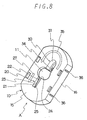
- Fig. 8 illustrates a needle-detaching device A′ in accordance with this embodiment.
- the needle-detaching device A′ comprises a plate-like member 10, a first opening 11 for inserting the lower portion of a syringe S provided in the central portion of the member 10, a first needle-detaching means 20 for a slip type needle and a second needle-detaching means 30 for a screw type needle, the means 20 and the means 30 being provided on the opposed sides of the first opening 10.
- the first needle-detaching means 20 has substantially the same construction and function as the above-mentioned first needle-detaching means 3.
- the needle-detaching device A′ when being used, is mounted on a container B′ for containing used needles, as shown in Fig. 14.
- the shape of the container B′ is not particularly limited.
- An opening 12 is provided in a part of container B′, and a rib 13 and engaging projections 14 are provided in the periphery of the opening 12 to install the needle-detaching device A′.
- the plate-like member 10 comprises an upper plate 15 and a skirt 16 provided in the periphery of the upper plate 15.
- the plate-like member 10 is integrally formed from a synthetic resin such as polyethylene, polypropyrene, acrylonitril-butadiene-styrene copolymer, polycarbonate or polyester.
- the upper plate 15 has an opening 11 provided in the central portion thereof.
- the opening 11 is nearly elliptical in shape and has such a size that the hub 44 of the needle 43 can be inserted thereinto.
- the opening 11 preferably has a size larger than the diameter of the protector so that the needle 43 covered with the protector can be detached from the syringe S.
- the first needle detaching means 20 comprises a second opening 21 extending from and communicating with the first opening 11, and a sliding portion 22 provided on each of both sides of the second opening 21.
- Each sliding portion 22 has a side wall 23 defining the second opening 21.
- Each sliding portion 22 is formed so that the side wall 23 is the thinnest at the entrance 24 of the second opening 21 and made gradually thicker toward the closed end 25 of the second opening 21.
- the width of the second opening 21 is somewhat larger than the diameter of the nozzle 41 and must be smaller than that of the barrel 40 and that of the hub 44.
- the thickness of the thinnest part of the side wall 23, i.e. the thickness of the side wall 23 at the entrance 24, must be smaller than the distance D between the root of the nozzle 41 and the bottom surface of the hub 44 when the hub 44 is firmly put on the nozzle 41.
- the thickest part of the side wall 23 must have a thickness sufficient to detach the hub 44 from the nozzle 41.
- the thickest part of the side wall 23 has a thickness larger than the distance D between the root of the nozzle 41 and the bottom surface of the hub 44 when the hub 44 is firmly put on the nozzle 41.
- the sliding surface 26 of the sliding portion 22 on the rear side of the plate 15, on which the bottom surface of the hub 44 slides, is inclined both in the direction of the first opening 11 and in the direction of the second opening 21.
- an arrow mark 27 for indicating the movement direction of the syringe S is provided on a side of the second opening 21 on the plate 15.
- the second needle-detaching means 30 contains a third opening 31 having a U shape in plain.
- the third opening 31 comprises a big-sized portion 32 having such a size that the hub 44 of the needle 43 is easily inserted thereinto and a small-sized portion 33 extending vertically from the big-sized portion 32 and having such a size that only the tip portion of the hub 44 can be inserted thereinto.
- the small-sized portion 33 has a projection 34 formed on a part of the side wall thereof. The projection 34 serves to prevent the rotation of the hub 44 due to the engagement of the projection 34 with the rib 45 of the hub 44.
- the reason why the small-sized portion 33 is provided under the big-sized portion 32 and the projection 34 is provided in the small-sized portion 33 is that the center of gravity of the needle 43 when being inserted in the third opening 31 is positioned under the upper surface of the plate 15, thereby preventing the detached needle 43 from falling out of the device A′.
- an arrow mark 35 for indicating the direction of the rotation of the syringe S is provided around the third opening 31.
- the skirt 16 has two slits 36, 36 on each of the opposed sides thereof so that a part of the skirt 16 between the two slits 36, 36 is made somewhat flexible.
- the part of the skirt 16 between the two slits 36, 36 has engaging projections 17 on the rear surface thereof.
- the engaging projections 17 are engaged with the engaging projections 14 of the container B′.
- the number of the projections 17 are not particularly limited. In this example, two projections on each side of the skirt 16, four projections in total, are formed.
- the device A′ is installed to the container B′ by resiliently engaging the projections 14 of the container B′ with the projections 17 of the device A′.
- Fig. 15 illustrates the operation of detaching a slip type needle.
- the lower portion of the injection barrel 40 is inserted into the first opening 11 and put on the entrance 24 of the second opening 21.
- the nozzle 41 is inserted between both side walls 23, 23 and the shoulder portion 42 is brought into contact with the upper surfaces of the sliding portions 22 and the bottom surface of the hub 44 is brought into contact with the sliding surfaces 26, 26.
- the hub 44 is pushed downward because of increasing thickness of each sliding portion 22, thereby separating the hub 44 from the nozzle 41.
- the device A′ is preferably installed to the container B′ so that the barrel 40 can be moved downward as shown in Fig. 14 because it is easy to apply force on the barrel 40.
- Fig. 16 illustrates the operation of detaching a screw type needle.
- the lower portion of the injection barrel 40 is inserted downward into the third opening 30 and the hub 44 is inserted into the small-sized portion 33, engaging the rib 45 of the hub 44 with the projection 34.
- the needle 43 is loosened and detached from the nozzle 41.
- the barrel 40 is turned about one turn, followed by movement toward the first opening 11.
- the hub 44 is turned in such a manner that it crosses the projection 34, whereby the hub 44 is unthreaded and detached from the nozzle 41.
- an injection needle can be detached without touching the tip of the injection needle with finger. Further an injection needle can be detached by using only the device A′ regardless of whether the needle is a slip type needle or a screw type needle.
- the device A′ of the above-mentioned example is nearly elliptical in plane shape.
- the device A′ may be circular in plane shape.
- the skirt 16 can be designed so that it can be installed to a container by fitting or screwing.
- the device A′ having such a skirt 16 can be installed to a suitable bottle as the container B′. In that case, no individually designed container is needed.
- an injection needle can be readily detached with safety without injuring the finger. Further detachment of both a slip type needle and a screw type needle can be effected by using only the device A′.
Abstract
Description
- The present invention relates to an injection needle-detaching device and a container equipped with said device for containing used injection needles. More particularly, the present invention relates to a device for detaching a used needle from a syringe with safety without touching the needle with finger and a container equipped with the needle-detaching device for containing the detached needle directly therein.
- There are two kinds of injection needles with respect to the manner of attaching the needle to a syringe. The one is a slip type wherein a needle has a hub with a plain inner surface and the hub is simply forced to be put on the nozzle portion of a syringe that has a plain outer surface. The other is a screw type wherein a needle has a hub having a female thread on the inner surface thereof and the hub is threaded onto the nozzle portion of a syringe that has a male thread on the outer surface thereof.
- Conventionally, the injection needle was detached from the syringe by simply pulling out it or by unthreading it with holding the hub thereof with fingers. At the first glance, such detaching operation appears to be easy. However, an accident that finger is injured with the needle inevitably happens when the same person repeats the needle-detaching operation several tens times or more a day.
- Recently diseases infectious through blood such as viral hepatitis and acquired immuno-deficiency syndrome (AIDS) have increased rapidly. For the reason, it is important that persons who are engaged in test for the diseases and treatment of the diseases get out of direct touch with the blood of patients.
- However, when a used needle is detached from a syringe in the conventional manner, there is a great possibility that a person gets hurt in the finger with the needle and the blood attached to the needle is entered into the body of the person through the wound so that the person is infected with the above-mentioned disease.
- Accordingly, there is a demand for a means of detaching the needle from the syringe without touching the needle with finger.
- With respect to blood-drawing needle which generally has two needles extending in the opposed directions from the hub, a needle-receiving container in compliance with the demand is proposed, as disclosed in United States Patent No. 4,466,538. The container is provided with a slot which has a large width at one end and is narrowed toward the other end. A blood-drawing needle attached to a syringe is inserted into the wide portion of the slot and then moved toward the narrow portion, thereby catching the hub of the needle between both the side walls of the narrow portion. When the syringe is turned in such a state, the engagement between the syringe and the needle is loosened, so that the needle falls into the container.
- However, the container has a drawback that since the hub of the needle is firmly caught between the side walls when the syringe is turned, the needle tends to remain in that position without falling into the container and the operator gets hurt in the finger with the needle when he touches the needle to remove the caught needle.
- It is an object of the present invention to provide a needle-detaching device capable of detaching a used needle from a syringe with an easy operation without touching the needle with finger.
- Another object of the invention is to provide a needle-detaching device for a slip type needle.
- Further object of the invention is to provide a needle-detaching device having both a needle-detaching function for a slip type needle and a needle-detaching function for a screw type needle.
- Still further object of the invention is to provide a container equipped with the above-mentioned needle-detaching device and for detaching a used needle from a syringe and containing the detached needle directly therein.
- These and other objects of the present invention will become apparent from the description hereinafter.
- The present invention provides a device for detaching an injection needle from a syringe comprising:
a plate-like member,
a first opening provided in the plate-like member for inserting an injection needle attached to a syringe, and
a first needle-detaching means for detaching a slip type needle,
said first opening having a size larger than the largest part of said needle,
said first needle-detaching means comprising a second opening extending laterally from said first opening, and a sliding portion provided on each of both sides of said second opening,
said second opening having a width larger than the diameter of the nozzle of said syringe and smaller than the diameter of the hub of said needle,
each of said sliding portion having a side wall defining said second opening,
each of said side walls having, at the entrance of the second opening from said first opening, a thickness smaller than a distance between the root of the nozzle of said syringe and the bottom end of the hub of said needle when the needle is being attached to said syringe, each of said side walls being made gradually thicker toward the closed end of said second opening till the maximum thickness of each side wall becomes larger than said distance. - The present invention further provides a needle-detaching device containing a needle-detaching means for detaching a screw type needle in addition to the above-mentioned needle-detaching means for detaching the slip type needle,
said former needle-detaching means comprising a third opening extending laterally from said first opening,
said third opening having a portion having a size that the hub of said needle is capable of being inserted thereinto, said portion being provided with a projection for preventing the hub of said needle from turning when the syringe is turned. - The present invention further provides a container for used injection needles equipped with the above-mentioned needle-detaching device.
- Fig. 1 is a perspective view showing a container for containing used injection needles equipped with an embodiment of the needle-detaching device of the present invention.
- Fig. 2 is a partially broken, enlarged perspective view showing an example of the needle-detaching means of the device shown in Fig. 1, viewed from the inside of the container.
- Fig. 3 is a partially broken, enlarged perspective view showing another example of the needle-detaching means, viewed from the inside of the container.
- Fig. 4 is a partial sectional view showing a state wherein a syringe is inserted in the needle-detaching means shown in Fig. 2, corresponding to a section taken along the line I-I in Fig. 1.
- Fig. 5 is a partial sectional view showing the same state as illustrated in Fig. 4, but corresponding to a section taken along with the line II-II.
- Fig. 6 is a partial sectional view showing a state wherein a syringe is inserted in the needle-detaching means shown in Fig. 3, corresponding to a section taken along the line I-I in Fig. 1.
- Fig. 7 is a partial sectional view showing the same state as illustrated in Fig. 6, but corresponding to a section taken along the line II-II in Fig. 1.
- Fig. 8 is a perspective view showing another embodiment of the needle-detaching device of the present invention.
- Fig. 9 is a plan view showing the device illustrated in Fig. 8.
- Fig. 10 is an elevational view showing the device illustrated in Fig. 8.
- Fig. 11 is a sectional view taken along the line III-III in Fig. 9.
- Fig. 12 is a sectional view taken along the line IV-IV in Fig. 9.
- Fig. 13 is a sectional view taken along the line V-V in Fig. 9.
- Fig. 14 is a perspective view showing the needle-detaching device illustrated in Fig. 8 and a container on which the needle-detaching device is to be mounted.
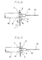
- Fig. 15 is an explanatory view showing the needle-detaching operation with respect to a slip type needle.
- Fig. 16 is an explanatory view showing the needle-detaching operation with respect to a screw type needle.
- Fig. 17 is an explanatory view showing a syringe.
- First a syringe and an injection needle are explained in order to give a better understanding of the description hereinafter.
- Referring to Fig. 17, the
numeral 40 indicates a barrel of a syringe S. Thesyringe barrel 40 has anozzle 41 at one end. Thenumeral 42 indicates a shoulder portion at the root of thenozzle 41. Thenumeral 43 indicates an injection needle and theinjection needle 43 extends from ahub 44. - The above-mentioned elements are fundamental elements common to both a slip type needle and a screw type needle. In the case of the slip type needle, the
hub 44 has a cavity with a plain inner surface and thecorresponding nozzle 41 also has a plain outer surface. In the case of the screw type needle, thehub 44 has an inner surface provided with a female thread and thecorresponding nozzle 41 has an outer surface provided with a male thread.Plural ribs 45 are provided on the outer surface of thehub 44 in the longitudinal direction thereof for the purpose of providing a moderate fitting strength between thehub 44 and a protector for theneedle 43. - In the present invention, the term "syringe" is intended to comprehend a blood-collecting tube in addition to a normal syringe. Also the term "injection needle" is intended to comprehend a blood-drawing needle in addition to a normal injection needle.
- Referring to Figs. 1 to 7, an embodiment of a needle-detaching device for the slip type needle in accordance with the present invention will be explained.
- Fig. 1 shows a container B for used needles in which a needle-detaching device A is provided.
- The device A is mounted on an inclined plane of the container B. Needles detached from syringes by means of the device A are contained within the container B.
- The construction of the container B is not limited to that illustrated in Fig. 1. The container B is made of wood, plastics, metal, etc. In the example shown in Fig. 1, the needle-detaching device A is installed only on one surface of the container B. However, a plurality of the device A may be installed on two or more surfaces of the container B.
- The device A comprises a plate-
like member 1, afirst opening 2 for inserting an injection needle provided in the plate-like member 1 and a first needle-detaching means 3 for a slip type needle. - The needle-inserting
opening 2 has a size larger than the largest part of aninjection needle 43. Usually the largest part is ahub 44. However, when a protector is put on theneedle 43, the largest part is the protector if the diameter of the protector is larger than that of thehub 44. Preferably theopening 2 has a size smaller than the diameter of thebarrel 40 of the syringe S. - The first needle-detaching means 3 comprises a
second opening 4 extending laterally from the needle-insertingopening 2 and communicating with theopening 2, and a slidingportion 5 provided on each of both sides of thesecond opening 4. - The
second opening 4 has a width larger than the diameter of thenozzle 41 of the syringe S and smaller than the diameter of thehub 44, as shown in Fig. 5 and Fig. 7. - Each of the sliding
portions 5 has aside wall 6 defining thesecond opening 4. - Each
side wall 6 has, at theentrance 7 of thesecond opening 4 from thefirst opening 2, a thickness T₁ smaller than a distance D between the root of thenozzle 41 and the bottom end of thehub 44 when theneedle 43 is being firmly attached to the syringe S, and eachside wall 6 is made gradually thicker toward theclosed end 8 of thesecond opening 4 and the maximum thickness T₂ of eachside wall 6 at theclosed end 8 is larger than the distance D, as shown in Figs. 2, 3, 4 and 6. - The shape of the
second opening 4 is usually a rectangle in plane as shown in Fig. 1. However, the width of thesecond opening 4 may be made smaller toward theclosed end 8. Further, the length of thesecond opening 4 may be reduced so that the plane shape becomes similar to a regular square. - In the case of an example of the needle- detaching means 3 as shown in Figs. 2, 4 and 5, the
side wall 6 has the same thickness T₁ as that of the plate-like member 1 at theentrance 7 but the remaining parts of theside wall 6 are thicker than themember 1. The surface 9 of the slidingportion 5 on the rear side of themember 1 constitutes a sliding surface on which the bottom surface of thehub 44 slides. Both sliding surfaces 9, 9 are flash with each other. - In the case of another example of the needle-detaching means 3 in Figs. 3, 6 and 7, the
side wall 6 has the same thickness T₂ as that of the plate-like member 1 at theclosed end 8 but the remaining parts of theside wall 6 are thinner than themember 1. The surface 9 of the slidingportion 5 on the rear side of themember 1 constitutes a sliding surface on which the bottom surface of thehub 44 slides. Each sliding surface 9 is inclined both in the direction of thefirst opening 2 and in the direction of thesecond opening 4. - The
side wall 6 must have a maximum thickness T₂ sufficient to remove thehub 44 from thenozzle 41. The maximum thickness T₂ is larger than a distance D between the root of thenozzle 41 and the bottom surface of thehub 44 to surely detach thehub 44 from thenozzle 41. - Further the angle α between both edge lines of the
side wall 6 in the longitudinal direction of thesecond opening 4 is preferably from 5° to 45°, more preferably from 15° to 30°, to facilitate a smooth removal of thehub 44 from thenozzle 41. - The needle-detaching operation using the needle-detaching device A shown in Fig. 2 will be explained by referring to Figs. 4 and 5.
- Fig. 4 and Fig. 5 are a sectional view taken along the line I-I of Fig. 1 and a sectional view taken along the line II-II of Fig. 1, respectively, when the syringe S is positioned on the line II-II of Fig. 1.
- The lower portion of the syringe S to which the
needle 43 is attached is inserted into thefirst opening 2 until theshoulder portion 42 of thebarrel 40 is brought into contact with the pheriphery of thefirst opening 2 and then moved into thesecond opening 4, followed by further movement toward theclosed end 8. When the syringe S is moved toward theclosed end 8 in the direction of the arrow M, bothside walls shoulder portion 42 of thebarrel 40 and the bottom surface of thehub 44 like a wedge because of increasing thickness of eachside wall 6. As a result, thehub 44 is pushed downward so that it is loosened and finally separated from thenozzle 41. - The needle-detaching operation using the needle-detaching device A shown in Fig. 3 will be explained by referring to Figs. 6 and 7.
- Fig. 6 and Fig. 7 are a sectional view taken along the line I-I of Fig. 1 and a sectional view taken along the line II-II of Fig. 1, respectively, when the syringe S is positioned on the line II-II of Fig. 1.
- The needle-detaching device A shown in Fig. 3 is preferably used when the thickness of the plate-
like member 1 is larger than the distance D between the root of thenozzle 41 and the bottom surface of thehub 44. - The lower portion of the syringe S to which the
needle 43 is attached is inserted into thefirst opening 2 until theshoulder portion 42 of thebarrel 40 is brought into contact with the pheriphery of thefirst opening 2 and then moved into thesecond opening 4. Bothside walls shoulder portion 42 of thebarrel 40 and the bottom surface of thehub 44 at theentrance 7. When the syringe S is further moved toward theclosed end 8 of thesecond opening 4, thehub 44 is gradually spaced apart from theshoulder portion 42 of thebarrel 40 and finally separated from thenozzle 41, the separatedneedle 43 falling within the container B. - When used needles are accumulated in the container B, the container B is closed and subjected to a discarding treatment such as burning.
- The device A and the container B can be manufactured by a conventional method. For instance, when the material is plastics, they can be injection-molded.
- By using the needle-detaching device A of the present invention, a needle to which blood is attached can be detached smoothly from a syringe with an easy operation without touching the needle with the hand.
- Further, the side walls are inserted into the spacing between the shoulder portion of the barrel and the bottom surface of the hub like a wedge, so that the hub is spaced apart from the nozzle and finally separated from the nozzle. Accordingly, there does not occur the problem of the conventional device that since the needle is caught in the device because of twisting the hub thereof to loosen it, a person such as doctor must remove the caught needle from the device by touching it with the hand, and there is no danger of infection.
- Another embodiment of the needle-detaching device of the present invention will be explained by referring to Figs. 8 to 16. The device of this embodiment has both the function of detaching a slip type needle and the function of detaching a screw type needle.
- Fig. 8 illustrates a needle-detaching device A′ in accordance with this embodiment. The needle-detaching device A′ comprises a plate-
like member 10, afirst opening 11 for inserting the lower portion of a syringe S provided in the central portion of themember 10, a first needle-detaching means 20 for a slip type needle and a second needle-detaching means 30 for a screw type needle, themeans 20 and themeans 30 being provided on the opposed sides of thefirst opening 10. - The first needle-detaching means 20 has substantially the same construction and function as the above-mentioned first needle-detaching
means 3. - The needle-detaching device A′, when being used, is mounted on a container B′ for containing used needles, as shown in Fig. 14. The shape of the container B′ is not particularly limited. An opening 12 is provided in a part of container B′, and a rib 13 and engaging
projections 14 are provided in the periphery of the opening 12 to install the needle-detaching device A′. - The construction of the needle-detaching device A′ will be explained in detail by referring to Figs. 8 to 13.
- The plate-
like member 10 comprises anupper plate 15 and askirt 16 provided in the periphery of theupper plate 15. The plate-like member 10 is integrally formed from a synthetic resin such as polyethylene, polypropyrene, acrylonitril-butadiene-styrene copolymer, polycarbonate or polyester. - The
upper plate 15 has anopening 11 provided in the central portion thereof. Theopening 11 is nearly elliptical in shape and has such a size that thehub 44 of theneedle 43 can be inserted thereinto. When theneedle 43 is covered with a protector, theopening 11 preferably has a size larger than the diameter of the protector so that theneedle 43 covered with the protector can be detached from the syringe S. - The first needle detaching means 20 comprises a
second opening 21 extending from and communicating with thefirst opening 11, and a slidingportion 22 provided on each of both sides of thesecond opening 21. - Each sliding
portion 22 has aside wall 23 defining thesecond opening 21. Each slidingportion 22 is formed so that theside wall 23 is the thinnest at theentrance 24 of thesecond opening 21 and made gradually thicker toward theclosed end 25 of thesecond opening 21. - The width of the
second opening 21 is somewhat larger than the diameter of thenozzle 41 and must be smaller than that of thebarrel 40 and that of thehub 44. - The thickness of the thinnest part of the
side wall 23, i.e. the thickness of theside wall 23 at theentrance 24, must be smaller than the distance D between the root of thenozzle 41 and the bottom surface of thehub 44 when thehub 44 is firmly put on thenozzle 41. The thickest part of theside wall 23 must have a thickness sufficient to detach thehub 44 from thenozzle 41. The thickest part of theside wall 23 has a thickness larger than the distance D between the root of thenozzle 41 and the bottom surface of thehub 44 when thehub 44 is firmly put on thenozzle 41. The slidingsurface 26 of the slidingportion 22 on the rear side of theplate 15, on which the bottom surface of thehub 44 slides, is inclined both in the direction of thefirst opening 11 and in the direction of thesecond opening 21. - Preferably an
arrow mark 27 for indicating the movement direction of the syringe S is provided on a side of thesecond opening 21 on theplate 15. - The second needle-detaching means 30 contains a
third opening 31 having a U shape in plain. Thethird opening 31 comprises a big-sized portion 32 having such a size that thehub 44 of theneedle 43 is easily inserted thereinto and a small-sized portion 33 extending vertically from the big-sized portion 32 and having such a size that only the tip portion of thehub 44 can be inserted thereinto. The small-sized portion 33 has aprojection 34 formed on a part of the side wall thereof. Theprojection 34 serves to prevent the rotation of thehub 44 due to the engagement of theprojection 34 with therib 45 of thehub 44. - The reason why the small-
sized portion 33 is provided under the big-sized portion 32 and theprojection 34 is provided in the small-sized portion 33 is that the center of gravity of theneedle 43 when being inserted in thethird opening 31 is positioned under the upper surface of theplate 15, thereby preventing thedetached needle 43 from falling out of the device A′. - Preferably an
arrow mark 35 for indicating the direction of the rotation of the syringe S is provided around thethird opening 31. - The
skirt 16 has twoslits skirt 16 between the twoslits skirt 16 between the twoslits projections 17 on the rear surface thereof. The engagingprojections 17 are engaged with the engagingprojections 14 of the container B′. The number of theprojections 17 are not particularly limited. In this example, two projections on each side of theskirt 16, four projections in total, are formed. The device A′ is installed to the container B′ by resiliently engaging theprojections 14 of the container B′ with theprojections 17 of the device A′. - The operation of detaching an injection needle from a syringe by means of the device A′ is explained.
- Fig. 15 illustrates the operation of detaching a slip type needle. The lower portion of the
injection barrel 40 is inserted into thefirst opening 11 and put on theentrance 24 of thesecond opening 21. Thenozzle 41 is inserted between bothside walls shoulder portion 42 is brought into contact with the upper surfaces of the slidingportions 22 and the bottom surface of thehub 44 is brought into contact with the slidingsurfaces injection barrel 40 is moved in the direction of the arrow M, thehub 44 is pushed downward because of increasing thickness of each slidingportion 22, thereby separating thehub 44 from thenozzle 41. The device A′ is preferably installed to the container B′ so that thebarrel 40 can be moved downward as shown in Fig. 14 because it is easy to apply force on thebarrel 40. - Fig. 16 illustrates the operation of detaching a screw type needle. The lower portion of the
injection barrel 40 is inserted downward into thethird opening 30 and thehub 44 is inserted into the small-sized portion 33, engaging therib 45 of thehub 44 with theprojection 34. When thebarrel 40 is turned several turns in the direction of the arrow T in such a state, theneedle 43 is loosened and detached from thenozzle 41. Alternatively thebarrel 40 is turned about one turn, followed by movement toward thefirst opening 11. In that case, thehub 44 is turned in such a manner that it crosses theprojection 34, whereby thehub 44 is unthreaded and detached from thenozzle 41. - As described above, by using the needle-detaching device A′, an injection needle can be detached without touching the tip of the injection needle with finger. Further an injection needle can be detached by using only the device A′ regardless of whether the needle is a slip type needle or a screw type needle.
- The device A′ of the above-mentioned example is nearly elliptical in plane shape. However the device A′ may be circular in plane shape. In that case, the
skirt 16 can be designed so that it can be installed to a container by fitting or screwing. The device A′ having such askirt 16 can be installed to a suitable bottle as the container B′. In that case, no individually designed container is needed. - By using the needle-detaching device A′ of the present invention, an injection needle can be readily detached with safety without injuring the finger. Further detachment of both a slip type needle and a screw type needle can be effected by using only the device A′.
- In addition to the elements used in the Examples, other elements can be used in the Examples as set forth in the specification and the drawings to obtain substantially the same results.
Claims (6)
a plate-like member,
a first opening provided in the plate-like member for inserting an injection needle attached to a syringe, and
a first needle-detaching means for detaching a slip type needle,
said first opening having a size larger than the largest part of said needle,
said first needle-detaching means comprising a second opening extending laterally from said first opening, and a sliding portion provided on each of both sides of said second opening,
said second opening having a width larger than the diameter of the nozzle of said syringe and smaller than the diameter of the hub of said needle,
each of said sliding portion having a side wall defining said second opening,
each of said side walls having, at the entrance of the second opening from said first opening, a thickness smaller than a distance between the root of the nozzle of said syringe and the bottom end of the hub of said needle when the needle is being attached to said syringe, each of said side walls being made gradually thicker toward the closed end of said second opening, the maximum thickness of each of said side walls being larger than said distance.
said means comprising a third opening extending laterally from said first opening,
said third opening having a portion having a size that the hub of said needle is capable of being inserted thereinto, said portion being provided with a projection for preventing the hub of said needle from turning when the syringe is turned.
a container, and
a needle-detaching device as recited in Claim 1 provided in a part of the container.
Applications Claiming Priority (4)
| Application Number | Priority Date | Filing Date | Title |
|---|---|---|---|
| JP117564/87U | 1987-07-31 | ||
| JP1987117564U JPS6422358U (en) | 1987-07-31 | 1987-07-31 | |
| JP189702/87U | 1987-12-14 | ||
| JP1987189702U JPH0336362Y2 (en) | 1987-12-14 | 1987-12-14 |
Publications (3)
| Publication Number | Publication Date |
|---|---|
| EP0304619A2 true EP0304619A2 (en) | 1989-03-01 |
| EP0304619A3 EP0304619A3 (en) | 1989-03-08 |
| EP0304619B1 EP0304619B1 (en) | 1991-10-16 |
Family
ID=26455657
Family Applications (1)
| Application Number | Title | Priority Date | Filing Date |
|---|---|---|---|
| EP88111643A Expired - Lifetime EP0304619B1 (en) | 1987-07-31 | 1988-07-20 | Injection needle-detaching device and container having said device |
Country Status (4)
| Country | Link |
|---|---|
| EP (1) | EP0304619B1 (en) |
| CN (1) | CN1021293C (en) |
| DE (1) | DE3865591D1 (en) |
| MY (1) | MY102838A (en) |
Cited By (13)
| Publication number | Priority date | Publication date | Assignee | Title |
|---|---|---|---|---|
| EP0355391A1 (en) * | 1988-07-19 | 1990-02-28 | HOLTSCH Metallwarenherstellung Maria Holtsch | Container for dispersing dry or premoisturised fabrics, particularly swabs impregnated with alcohol, convertible in a litter bin preferably for spent catheters |
| EP0441628A2 (en) * | 1990-02-09 | 1991-08-14 | Damal Limited | Hypodermic needle/syringe assemblies and device for removing needles therefrom |
| WO1991016089A1 (en) * | 1990-04-26 | 1991-10-31 | Ab Västsvensk Medicinteknik | A device for disposing used syringe needles |
| EP0455329A2 (en) * | 1990-03-26 | 1991-11-06 | Med-Safe Systems, Inc. | Restricted access opening for disposable sharps containers |
| EP0515962A1 (en) * | 1991-05-31 | 1992-12-02 | Medical Safety Products, Inc. | Needle disposal container |
| EP0597063A1 (en) * | 1992-05-26 | 1994-05-18 | BUTLER, William F. | Method and apparatus for electrically destroying a syringe needle |
| FR2717087A1 (en) * | 1994-03-08 | 1995-09-15 | Charpentier Daniel | Medical needle destruction unit |
| FR2758454A1 (en) * | 1997-01-17 | 1998-07-24 | Nestor Basquin | Receptacle for hazardous medical waste |
| DE19734129A1 (en) * | 1997-08-07 | 1999-02-11 | Rigling Gmbh | Holder with reliable release mechanism for used cannulae |
| US6036671A (en) * | 1997-07-17 | 2000-03-14 | Frey; William J. | Breakaway syringe and disposal apparatus |
| WO2001058776A1 (en) * | 2000-02-11 | 2001-08-16 | Emballator Ulricehamns Bleck Ab | Cover for cans |
| EP1396234A1 (en) * | 2002-09-06 | 2004-03-10 | Becton, Dickinson and Company | Pen needle sharps port |
| GB2398249B (en) * | 2001-11-30 | 2005-11-16 | Segal Alan J | Safety syringe with re-usable main parts, method for disposal of a needle into a container and container for disposable parts |
Families Citing this family (6)
| Publication number | Priority date | Publication date | Assignee | Title |
|---|---|---|---|---|
| IN189561B (en) | 1996-06-21 | 2003-03-29 | Bio Plexus Inc | |
| JP4472522B2 (en) * | 2002-07-03 | 2010-06-02 | ノボ・ノルデイスク・エー/エス | Needle mounting system and needle assembly mounting method |
| DE102007022404A1 (en) * | 2007-05-10 | 2008-11-13 | B. Braun Melsungen Ag | Device for holding a cannula and detachable device on a device for injecting fluids |
| CN104857599B (en) * | 2015-04-21 | 2023-06-13 | 湖南中医药大学 | Safety operating device for injector |
| CN105292845A (en) * | 2015-11-19 | 2016-02-03 | 广西佳华医疗卫生用品有限公司 | Edged tool box with syringe needle convenient pull-out function |
| CN108744166B (en) * | 2018-04-09 | 2024-03-19 | 宁波新跃医疗科技股份有限公司 | Needle separator |
Citations (5)
| Publication number | Priority date | Publication date | Assignee | Title |
|---|---|---|---|---|
| WO1982000412A1 (en) * | 1980-08-06 | 1982-02-18 | B Elisha | Disposal of needles |
| EP0136392A1 (en) * | 1983-08-08 | 1985-04-10 | Ch'ing-Lung Hsieh | Mini electrical syringe needle destroyer |
| DE8614635U1 (en) * | 1986-05-30 | 1986-09-04 | Zanker, Helmut, 7000 Stuttgart | Medical device combination with holder |
| DE8708179U1 (en) * | 1987-06-10 | 1987-09-17 | Brecht, Thorsten, 2000 Hamburg, De | |
| WO1988000067A1 (en) * | 1986-07-09 | 1988-01-14 | Anthony Lees | Containers |
-
1988
- 1988-07-20 EP EP88111643A patent/EP0304619B1/en not_active Expired - Lifetime
- 1988-07-20 DE DE8888111643T patent/DE3865591D1/en not_active Expired - Fee Related
- 1988-07-21 MY MYPI88000815A patent/MY102838A/en unknown
- 1988-07-30 CN CN88104702.3A patent/CN1021293C/en not_active Expired - Fee Related
Patent Citations (5)
| Publication number | Priority date | Publication date | Assignee | Title |
|---|---|---|---|---|
| WO1982000412A1 (en) * | 1980-08-06 | 1982-02-18 | B Elisha | Disposal of needles |
| EP0136392A1 (en) * | 1983-08-08 | 1985-04-10 | Ch'ing-Lung Hsieh | Mini electrical syringe needle destroyer |
| DE8614635U1 (en) * | 1986-05-30 | 1986-09-04 | Zanker, Helmut, 7000 Stuttgart | Medical device combination with holder |
| WO1988000067A1 (en) * | 1986-07-09 | 1988-01-14 | Anthony Lees | Containers |
| DE8708179U1 (en) * | 1987-06-10 | 1987-09-17 | Brecht, Thorsten, 2000 Hamburg, De |
Cited By (20)
| Publication number | Priority date | Publication date | Assignee | Title |
|---|---|---|---|---|
| EP0355391A1 (en) * | 1988-07-19 | 1990-02-28 | HOLTSCH Metallwarenherstellung Maria Holtsch | Container for dispersing dry or premoisturised fabrics, particularly swabs impregnated with alcohol, convertible in a litter bin preferably for spent catheters |
| US5356383A (en) * | 1990-02-09 | 1994-10-18 | Damal Limited | Hypodermic needle/syringe assemblies and device for removing needles therefrom |
| EP0441628A2 (en) * | 1990-02-09 | 1991-08-14 | Damal Limited | Hypodermic needle/syringe assemblies and device for removing needles therefrom |
| EP0441628A3 (en) * | 1990-02-09 | 1992-05-06 | Damal Limited | Hypodermic needle/syringe assemblies and device for removing needles therefrom |
| EP0455329A2 (en) * | 1990-03-26 | 1991-11-06 | Med-Safe Systems, Inc. | Restricted access opening for disposable sharps containers |
| EP0455329A3 (en) * | 1990-03-26 | 1991-11-13 | Med-Safe Systems, Inc. | Restricted access opening for disposable sharps containers |
| WO1991016089A1 (en) * | 1990-04-26 | 1991-10-31 | Ab Västsvensk Medicinteknik | A device for disposing used syringe needles |
| EP0515962A1 (en) * | 1991-05-31 | 1992-12-02 | Medical Safety Products, Inc. | Needle disposal container |
| US5273161A (en) * | 1991-05-31 | 1993-12-28 | Medical Safety Products, Inc. | Needle disposal system comprised of blood collection holder and companion biohazard receptacle |
| EP0597063A4 (en) * | 1992-05-26 | 1994-12-07 | William F Butler | Method and apparatus for electrically destroying a syringe needle. |
| EP0597063A1 (en) * | 1992-05-26 | 1994-05-18 | BUTLER, William F. | Method and apparatus for electrically destroying a syringe needle |
| FR2717087A1 (en) * | 1994-03-08 | 1995-09-15 | Charpentier Daniel | Medical needle destruction unit |
| FR2758454A1 (en) * | 1997-01-17 | 1998-07-24 | Nestor Basquin | Receptacle for hazardous medical waste |
| US6036671A (en) * | 1997-07-17 | 2000-03-14 | Frey; William J. | Breakaway syringe and disposal apparatus |
| DE19734129A1 (en) * | 1997-08-07 | 1999-02-11 | Rigling Gmbh | Holder with reliable release mechanism for used cannulae |
| DE19734129C2 (en) * | 1997-08-07 | 2000-06-21 | Rigling Gmbh | Cannula container |
| WO2001058776A1 (en) * | 2000-02-11 | 2001-08-16 | Emballator Ulricehamns Bleck Ab | Cover for cans |
| GB2398249B (en) * | 2001-11-30 | 2005-11-16 | Segal Alan J | Safety syringe with re-usable main parts, method for disposal of a needle into a container and container for disposable parts |
| EP1396234A1 (en) * | 2002-09-06 | 2004-03-10 | Becton, Dickinson and Company | Pen needle sharps port |
| JP2004261570A (en) * | 2002-09-06 | 2004-09-24 | Becton Dickinson & Co | Aperture for pen type injection needleaperture for pen type injection needle |
Also Published As
| Publication number | Publication date |
|---|---|
| DE3865591D1 (en) | 1991-11-21 |
| CN1021293C (en) | 1993-06-23 |
| MY102838A (en) | 1992-11-30 |
| EP0304619A3 (en) | 1989-03-08 |
| CN1030899A (en) | 1989-02-08 |
| EP0304619B1 (en) | 1991-10-16 |
Similar Documents
| Publication | Publication Date | Title |
|---|---|---|
| US4875265A (en) | Injection needle-detaching device | |
| EP0304619B1 (en) | Injection needle-detaching device and container having said device | |
| US4892191A (en) | Container having injection needle-detaching means | |
| US4908023A (en) | Syringe assembly | |
| US4906235A (en) | Needle guard | |
| US5601532A (en) | Locking safety cover for sharp instruments | |
| US5259840A (en) | Locking syringe | |
| US5242421A (en) | Needle cap | |
| EP0885621B1 (en) | Manually pivoted barrier assembly for a piercing element | |
| US5772638A (en) | Protector for needle | |
| EP0824895B1 (en) | Infectious waste container for blood collection needles | |
| US20040186446A1 (en) | Wing-like needle protector | |
| EP0460821A1 (en) | Safety needle containers | |
| JPH0669493B2 (en) | Retractable disposable hypodermic syringe and its handling method | |
| US6253916B1 (en) | Sharps disposal assembly having improved unwinder | |
| US5285896A (en) | Apparatus for receiving and capturing a hypodermic needle hub and cannula | |
| US3712302A (en) | Flexible needle guard for breaking syringe needles | |
| EP0222103B1 (en) | Blood collection needle disposal system | |
| EP1159983B1 (en) | Clamp for winged needle | |
| EP0425448B1 (en) | Safety cap for a medical needle after use | |
| EP0569233A1 (en) | Sharps handling apparatus | |
| AU750015B2 (en) | Needle holder assembly | |
| WO1982000412A1 (en) | Disposal of needles | |
| EP2073874B1 (en) | Needle safety device | |
| AU717410B2 (en) | Easy use needle protector sheath |
Legal Events
| Date | Code | Title | Description |
|---|---|---|---|
| PUAI | Public reference made under article 153(3) epc to a published international application that has entered the european phase |
Free format text: ORIGINAL CODE: 0009012 |
|
| PUAL | Search report despatched |
Free format text: ORIGINAL CODE: 0009013 |
|
| AK | Designated contracting states |
Kind code of ref document: A2 Designated state(s): BE CH DE ES FR GB IT LI NL SE |
|
| AK | Designated contracting states |
Kind code of ref document: A3 Designated state(s): BE CH DE ES FR GB IT LI NL SE |
|
| RHK1 | Main classification (correction) |
Ipc: A61M 5/32 |
|
| 17P | Request for examination filed |
Effective date: 19890818 |
|
| 17Q | First examination report despatched |
Effective date: 19900125 |
|
| GRAA | (expected) grant |
Free format text: ORIGINAL CODE: 0009210 |
|
| AK | Designated contracting states |
Kind code of ref document: B1 Designated state(s): DE IT NL |
|
| ITF | It: translation for a ep patent filed |
Owner name: ING. C. GREGORJ S.P.A. |
|
| REF | Corresponds to: |
Ref document number: 3865591 Country of ref document: DE Date of ref document: 19911121 |
|
| EN | Fr: translation not filed | ||
| PGFP | Annual fee paid to national office [announced via postgrant information from national office to epo] |
Ref country code: NL Payment date: 19920731 Year of fee payment: 5 |
|
| PLBE | No opposition filed within time limit |
Free format text: ORIGINAL CODE: 0009261 |
|
| STAA | Information on the status of an ep patent application or granted ep patent |
Free format text: STATUS: NO OPPOSITION FILED WITHIN TIME LIMIT |
|
| PGFP | Annual fee paid to national office [announced via postgrant information from national office to epo] |
Ref country code: DE Payment date: 19920910 Year of fee payment: 5 |
|
| 26N | No opposition filed | ||
| PG25 | Lapsed in a contracting state [announced via postgrant information from national office to epo] |
Ref country code: NL Effective date: 19940201 |
|
| NLV4 | Nl: lapsed or anulled due to non-payment of the annual fee | ||
| PG25 | Lapsed in a contracting state [announced via postgrant information from national office to epo] |
Ref country code: DE Effective date: 19940401 |
|
| PG25 | Lapsed in a contracting state [announced via postgrant information from national office to epo] |
Ref country code: IT Free format text: LAPSE BECAUSE OF NON-PAYMENT OF DUE FEES;WARNING: LAPSES OF ITALIAN PATENTS WITH EFFECTIVE DATE BEFORE 2007 MAY HAVE OCCURRED AT ANY TIME BEFORE 2007. THE CORRECT EFFECTIVE DATE MAY BE DIFFERENT FROM THE ONE RECORDED. Effective date: 20050720 |