EP0304562A2 - Method for bending a strip with a profiled region at its longitudinal edge - Google Patents
Method for bending a strip with a profiled region at its longitudinal edge Download PDFInfo
- Publication number
- EP0304562A2 EP0304562A2 EP88108853A EP88108853A EP0304562A2 EP 0304562 A2 EP0304562 A2 EP 0304562A2 EP 88108853 A EP88108853 A EP 88108853A EP 88108853 A EP88108853 A EP 88108853A EP 0304562 A2 EP0304562 A2 EP 0304562A2
- Authority
- EP
- European Patent Office
- Prior art keywords
- strip
- profile
- frame
- longitudinal edge
- bending
- Prior art date
- Legal status (The legal status is an assumption and is not a legal conclusion. Google has not performed a legal analysis and makes no representation as to the accuracy of the status listed.)
- Withdrawn
Links
Images


Classifications
-
- B—PERFORMING OPERATIONS; TRANSPORTING
- B21—MECHANICAL METAL-WORKING WITHOUT ESSENTIALLY REMOVING MATERIAL; PUNCHING METAL
- B21D—WORKING OR PROCESSING OF SHEET METAL OR METAL TUBES, RODS OR PROFILES WITHOUT ESSENTIALLY REMOVING MATERIAL; PUNCHING METAL
- B21D5/00—Bending sheet metal along straight lines, e.g. to form simple curves
- B21D5/06—Bending sheet metal along straight lines, e.g. to form simple curves by drawing procedure making use of dies or forming-rollers, e.g. making profiles
- B21D5/08—Bending sheet metal along straight lines, e.g. to form simple curves by drawing procedure making use of dies or forming-rollers, e.g. making profiles making use of forming-rollers
-
- B—PERFORMING OPERATIONS; TRANSPORTING
- B21—MECHANICAL METAL-WORKING WITHOUT ESSENTIALLY REMOVING MATERIAL; PUNCHING METAL
- B21D—WORKING OR PROCESSING OF SHEET METAL OR METAL TUBES, RODS OR PROFILES WITHOUT ESSENTIALLY REMOVING MATERIAL; PUNCHING METAL
- B21D19/00—Flanging or other edge treatment, e.g. of tubes
- B21D19/02—Flanging or other edge treatment, e.g. of tubes by continuously-acting tools moving along the edge
- B21D19/04—Flanging or other edge treatment, e.g. of tubes by continuously-acting tools moving along the edge shaped as rollers
- B21D19/043—Flanging or other edge treatment, e.g. of tubes by continuously-acting tools moving along the edge shaped as rollers for flanging edges of plates
Definitions
- the present invention relates to a method according to the preamble of patent claim 1.
- sealing strips are often to be installed between the frame and the door, which seal the interior of the control cabinet against the outside atmosphere.
- the attachment of such seals requires a corresponding front design (such as welded-on ribs or the like) of the frame, which takes place in several complex work steps in all known manufacturing processes.
- the design of the corners, in particular, requires special effort since the tightness must also be guaranteed there.
- the object of the present invention is to create a method which allows strips to be bent into frames and, at the same time, to design the front appropriately without requiring any subsequent effort.
- the invention relates to a frame produced by the method, which is characterized in that the side walls front and / or back along the Area (including the bends) are provided with a circumferential profile formed by plastic deformation.
- Such frames are particularly suitable as high-precision frames for control cabinets.
- the profile has a cone or pyramid-shaped suit against the front and / or back, in particular the profile following the cone or pyramid-shaped suit has a rib perpendicular to the plane of the front or back forms. If such a frame is used as a frame for a control cabinet, this embodiment has the advantage that a sealing strip can be reliably attached to the rib and supported tightly against the conical or pyramid-shaped suit without any additional work on the front design of the frame.
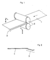
- the sheet metal strip 1 For the production of a metal frame profiled along the front or rear edge region (FIG. 7), the sheet metal strip 1 provided for this purpose is first cut to length according to the frame circumference. The transverse edges are to be aligned precisely with respect to the longitudinal center axis of the sheet metal strip 1, so that they meet with their end faces flush on the finished sheet metal strip, and the clear frame cross section is exactly achieved. After cutting to length, depending on the application requirement, the area 3 of a longitudinal edge of the metal strip 1 (or both) is provided with the desired profile between profiling rolls 2 or by means of a folding machine (FIGS. 1 and 2). If a sheet metal strip 1 prepared in this way is to be bent into a frame with a rectangular cross section (FIG. 2), its four corner regions are successively placed between a punch 4 and a die 5. If one of the corner areas is between the two tools 4 and 5, the die is pressed against the stationary punch and the sheet metal strip is bent by 90 °.
- the die 5 and the punch 4 protrude at right angles from a table plane 6 of a bending machine, on which the die 5 can be moved back and forth in the direction of the double arrow shown in FIG. 4 against the stationary punch 4.
- the die 5 can be driven mechanically or hydraulically.
- the flat surfaces 7 and 8 facing the die 4 on the die 5 intersect at right angles and are connected to one another by a fillet 9.
- the stamp 4 is provided with surfaces 7, 8, 9 corresponding parallel surfaces 10 to 12, the reference number 12 designating a rounded edge which fits into the fillet 9.
- the surfaces 7 to 9 and 10 to 12 in an area adjacent to the table plane 6 are provided with complementary shapes simulating the profile area 3.
- the profile of the sheet metal strip 1 also extends around its rounded corner edge after the die 5 has been pressed against the punch and the sheet metal strip has been bent through 90 °.
- the die 5 is provided with a rib 13 and the punch with a groove-like recess 14.
- the table level 6 is provided with an opening 16 through which excess material can escape downwards during the bending and pressing of the frame corners in the sheet metal strip.
- a knife can be moved between the position shown in FIG. 4 and the position shown in FIG. 6, the cutting edge of which moves in the table plane 6. After the pressing and bending process has been completed, this knife is used to shear off the downward-moving material which forms a flap 18, so that the corner regions in the frame front plane are also precisely coplanar.
- the method and the device function as follows.
- the edge area 3 is first profiled by rolling or bending on a sheet metal strip 1 (FIGS. 1 and 2). Before or after, the metal strip 1 is cut to length according to the circumference of the frame. The sheet metal strip 1 cut to length is then bent four times at right angles between the tools 4 and 5. Here, the geometric center lines of the provided corners 19, 21 to 23 are brought into contact with the center line of the rounded corner 12 of the punch 4 and the die 5 is pressed against the punch 4.
- the sheet metal strip 1 is bent by 90 °, the edge profiling on the sheet metal strip 1 being retained because of the complementary shapes of the rib 13 and the recess 14 and being forced in the region of the corners 19, 21 to 23.
- the edge profiling at the corners 19, 21 to 23 an excess of material arises in these areas, which escapes into the opening 16 in the form of a flap.
- the knife 17 is moved from its rear end position (FIG. 4) into the front end position (FIG. 6) and the tab as long as the tools 4 and 5 are still held in the closed and pressed position 18 sheared off.
- the corner regions 19, 21 to 23 are on the Front coplanar with the frame front level. After the fourth bend, the end faces of the metal strip 1 abut one another flush and can be welded by means of a seam 20.
- the example described above is not limited to frames with a rectangular or square light cross section.
- the clear cross section can also be a triangle or a polygon, a circle, an ellipse or the like, which only requires correspondingly designed surfaces 7 and 8 or 10 and 11 on the die 5 or the punch 4.
Abstract
Description
Die vorliegende Erfindung bezieht sich auf ein Verfahren gemäss dem Oberbegriff des Patentanspruchs 1.The present invention relates to a method according to the preamble of
Bei Schaltschränken sind zwischen Zarge und Türe oft Dichtungsstreifen anzubringen, die den Innenraum des Schaltschrankes gegen die Aussenatmosphäre abdichten. Das Anbringen solcher Dichtungen setzt eine entsprechende frontseitige Gestaltung (wie angeschweisste Rippen oder dgl.) der Zarge voraus, was bei allen bekannten Herstellungsverfahren in mehreren aufwendigen Arbeitsgängen erfolgt. Dabei erfordert insbesondere die Gestaltung der Ecken einen besonderen Aufwand, da auch dort die Dichtheit gewährleistet sein muss.In control cabinets, sealing strips are often to be installed between the frame and the door, which seal the interior of the control cabinet against the outside atmosphere. The attachment of such seals requires a corresponding front design (such as welded-on ribs or the like) of the frame, which takes place in several complex work steps in all known manufacturing processes. The design of the corners, in particular, requires special effort since the tightness must also be guaranteed there.
Die vorliegende Erfindung stellt sich die Aufgabe, ein Verfahren zu schaffen, das es erlaubt, Streifen zu Zargen zu biegen und gleichzeitig die Frontseite zweckmässig zu gestalten, ohne dass dadurch ein nachträglicher Aufwand erforderlich ist.The object of the present invention is to create a method which allows strips to be bent into frames and, at the same time, to design the front appropriately without requiring any subsequent effort.
Erfindungsgemäss wird diese Aufgabe gelöst durch die kennzeichnenden Merkmale des Anspruches 1.According to the invention, this object is achieved by the characterizing features of
Weiter bezieht sich die Erfindung auf einen nach dem Verfahren hergestellten Rahmen, der dadurch gekennzeichnet ist, dass dessen Seitenwände front- und/oder rückseitig entlang dem Bereich (unter Einschluss der Biegungen) mit einem umlaufenden, durch plastische Verformung gebildeten Profil versehen sind. Solche Rahmen eignen sich vorzüglich als hochpräzise Zargen für Schaltschränke.Furthermore, the invention relates to a frame produced by the method, which is characterized in that the side walls front and / or back along the Area (including the bends) are provided with a circumferential profile formed by plastic deformation. Such frames are particularly suitable as high-precision frames for control cabinets.
Nach einer bevorzugten Ausführungsform des Rahmens ist vorgesehen, dass das Profil gegen die Front- und/oder Rückseite einen kegel- oder pyramidenförmigen Anzug aufweist, wobei insbesondere das Profil anschliessend an den kegel- oder pyramidenförmigen Anzug eine zur Ebene der Front- oder Rückseite rechtwinklige Rippe bildet. Wird ein solcher Rahmen als Zarge für einen Schaltschrank verwandt, ergibt sich aus dieser Ausführungsform der Vorteil, dass ohne jede zusätzliche Arbeit an der frontseitigen Gestaltung der Zarge ein Dichtungsstreifen zuverlässig an der Rippe aufgesteckt und dicht gegen den kegel- oder pyramidenförmigen Anzug abgestützt werden kann.According to a preferred embodiment of the frame, it is provided that the profile has a cone or pyramid-shaped suit against the front and / or back, in particular the profile following the cone or pyramid-shaped suit has a rib perpendicular to the plane of the front or back forms. If such a frame is used as a frame for a control cabinet, this embodiment has the advantage that a sealing strip can be reliably attached to the rib and supported tightly against the conical or pyramid-shaped suit without any additional work on the front design of the frame.
Anhand der beiliegenden schematischen Zeichnung wird die Erfindung beispielsweise erläutert. Es zeigen:
- Fig. 1 das Profilieren eines Blechstreifens entlang einem seiner beiden Randbereiche,
- Fig. 2 einen Schnitt durch den profilierten Blechstreifen längs der Linie II-II,
- Fig. 3 eine perspektivische Darstellung des Biegens des profilierten Blechstreifens,
- Fig. 4 bis 6 einen Schnitt längs der Linie VI-VI in Fig. 3, wobei die Biegewerkzeuge in verschiedenen Stellungen gezeigt sind und
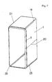
- Fig. 7 eine perspektivische Darstellung einer Zarge mit einem rechteckigen lichten Querschnitt.
- 1 the profiling of a sheet metal strip along one of its two edge areas,
- 2 shows a section through the profiled sheet metal strip along the line II-II,
- 3 is a perspective view of the bending of the profiled sheet metal strip,
- Fig. 4 to 6 is a section along the line VI-VI in Fig. 3, wherein the bending tools are shown in different positions and
- Fig. 7 is a perspective view of a frame with a rectangular clear cross section.
Für das Herstellen einer entlang dem vorderen oder hinteren Randbereich profilierten Metallzarge (Fig. 7) wird zuerst der hierfür vorgesehene Blechstreifen 1 entsprechend dem Zargenumfang abgelängt. Die Querkanten sind dabei genau mit Bezug auf die Längsmittelachse des Blechstreifens 1 auszurichten, so dass sie am fertig gebogenen Blechstreifen mit ihren Stirnseiten bündig aufeinander treffen, und der lichte Zargenquerschnitt dabei genau erreicht ist. Nach dem Ablängen wird, je nach Anwendungsbedürfnis, der Bereich 3 eines Längsrandes des Blechstreifens 1 (oder auch beide) zwischen Profilierwalzen 2 oder mittels einer Abkantmaschine mit dem gewünschten Profil versehen (Fig. 1 und 2). Ist ein derart vorbereiteter Blechstreifen 1 zu einer im Querschnitt rechteckigen Zarge (Fig. 2) zu biegen, werden nacheinander seine vier Eckbereiche zwischen einen Stempel 4 und eine Matrize 5 gebracht. Befindet sich jeweils einer der Eckbereiche zwischen den beiden Werkzeugen 4 und 5, wird die Matrize gegen den ruhenden Stempel gepresst und der Blechstreifen um 90° gebogen.For the production of a metal frame profiled along the front or rear edge region (FIG. 7), the
Die Matrize 5 und der Stempel 4 überragen rechtwinklig eine Tischebene 6 einer Biegemaschine, auf der die Matrize 5 in Richtung des in Fig. 4 eingezeichneten Doppelpfeils gegen den ruhenden Stempel 4 hin und her bewegbar ist. Der Antrieb der Matrize 5 kann mechanisch oder hydraulisch erfolgen. Bei der Herstellung einer Zarge mit rechteckigem lichtem Querschnitt schneiden sich die dem Stempel 4 zugewandten, ebenen Flächen 7 und 8 an der Matrize 5 rechtwinklig und sind durch eine Hohlkehle 9 miteinander verbunden. Der Stempel 4 ist mit den Flächen 7, 8, 9 entsprechenden parallelen Flächen 10 bis 12 versehen, wobei die Hinweisziffer 12 eine in die Hohlkehle 9 passende, gerundete Kante bezeichnet.The die 5 and the
Wie die Fig. 3 bis 6 zeigen, sind die Flächen 7 bis 9 und 10 bis 12 in einem an die Tischebene 6 angrenzenden Bereich mit komplementären, dem Profilbereich 3 nachgebildeten Formen versehen. Dadurch verläuft das Profil des Blechstreifens 1 auch um dessen gerundete Eckkante, nachdem die Matrize 5 gegen den Stempel gepresst und der Blechstreifen um 90° gebogen wurde. Zur Bildung der komplementären Formen ist die Matrize 5 mit einer Rippe 13 und der Stempel mit einer hohlkehlenartigen Ausnehmung 14 versehen.As shown in FIGS. 3 to 6, the surfaces 7 to 9 and 10 to 12 in an area adjacent to the
In der Verlängerung der gerundeten Kante 12 nach unten ist die Tischebene 6 mit einer Durchbrechung 16 versehen, durch welche während des Biegens und Pressens der Zargenecken im Blechstreifen überschüssiges Material nach unten ausweichen kann. In dieser Durchbrechung ist ein Messer zwischen der in Fig. 4 und der in Fig. 6 gezeigten Lage verschiebbar, dessen Schneidkante sich in der Tischebene 6 bewegt. Mit diesem Messer wird nach vollendetem Press- und Biegevorgang das nach unten ausweichende, einen Lappen 18 bildende Material abgeschert, so dass in der Zargenfrontebene auch die Eckbereiche genau coplanar ausgerichtet sind. Das Verfahren und die Vorrichtung funktionieren wie folgt.In the extension of the
Soll eine im lichten Querschnitt rechteckige Zarge entsprechend der Fig. 7 hergestellt werden, welche frontseitig einen profilierten Randbereich 3 und gerundete Ecken 19 aufweist (wobei das Profil des Bereiches 3 ohne Ausklinkung um die Ecke 19 herumgeführt sein muss) und die längs einer Naht 20 verschweisst ist, so wird zuerst an einem Blechstreifen 1 (Fig. 1 und 2) der Randbereich 3 durch Walzen oder Biegen entsprechend profiliert. Vorher oder danach wird der Blechstreifen 1 entsprechend dem Umfang der Zarge abgelängt. Der abgelängte Blechstreifen 1 wird darauf viermal zwischen den Werkzeugen 4 und 5 rechtwinklig gebogen. Hierbei werden nacheinander die geometrischen Mittellinien der vorgesehenen Ecken 19, 21 bis 23 in Anlage mit der Mittellinie der gerundeten Ecke 12 des Stempels 4 gebracht und die Matrize 5 gegen den Stempel 4 gepresst. Bei jedem dieser vier Biege- und Pressvorgänge wird der Blechstreifen 1 jeweils um 90° gebogen, wobei die Randprofilierung am Blechstreifen 1 wegen der komplementären Formen der Rippe 13 und der Ausnehmung 14 erhalten bleibt und im Bereich der Ecken 19, 21 bis 23 erzwungen wird. Während dieses Erzwingens der Randprofilierung an den Ecken 19, 21 bis 23 entsteht in diesen Bereichen ein Materialüberschuss, der in die Durchbrechung 16 lappenförmig ausweicht. Nach der Bildung der Lappen 18 wird, so lange die Werkzeuge 4 und 5 noch in der Schliess- und Pressstellung gehalten sind, das Messer 17 aus seiner hinteren Endlage (Fig. 4) in die vordere Endlage (Fig. 6) verschoben und der Lappen 18 abgeschert. Da der Blechstreifen 1 senkrecht mit seiner profilierten Kante auf der Tischebene 6 steht und die Schneidkante des Messers 17 sich in dieser Ebene bewegt, sind die Eckbereiche 19, 21 bis 23 auf der Frontseite coplanar mit der Zargenfrontebene. Nach der vierten Biegung stossen die endseitigen Stirnflächen des Blechstreifens 1 bündig aneinander und können mittels einer Naht 20 verschweisst werden.If a frame with a clear cross-section is to be produced according to FIG. 7, which has a profiled
Das vorbeschriebene Beispiel ist nicht auf Zargen mit rechteckigem oder quadratischem lichtem Querschnitt beschränkt. Der lichte Querschnitt kann auch ein Dreieck oder ein Vieleck, ein Kreis, eine Ellipse oder dgl. sein, was lediglich entsprechend ausgebildete Flächen 7 und 8 bzw. 10 und 11 an der Matrize 5 bzw. dem Stempel 4 erfordert.The example described above is not limited to frames with a rectangular or square light cross section. The clear cross section can also be a triangle or a polygon, a circle, an ellipse or the like, which only requires correspondingly designed
Claims (7)
Applications Claiming Priority (2)
| Application Number | Priority Date | Filing Date | Title |
|---|---|---|---|
| CH328187A CH674322A5 (en) | 1987-08-26 | 1987-08-26 | |
| CH3281/87 | 1987-08-26 |
Publications (2)
| Publication Number | Publication Date |
|---|---|
| EP0304562A2 true EP0304562A2 (en) | 1989-03-01 |
| EP0304562A3 EP0304562A3 (en) | 1989-08-09 |
Family
ID=4252585
Family Applications (1)
| Application Number | Title | Priority Date | Filing Date |
|---|---|---|---|
| EP88108853A Withdrawn EP0304562A3 (en) | 1987-08-26 | 1988-06-03 | Method for bending a strip with a profiled region at its longitudinal edge |
Country Status (2)
| Country | Link |
|---|---|
| EP (1) | EP0304562A3 (en) |
| CH (1) | CH674322A5 (en) |
Citations (4)
| Publication number | Priority date | Publication date | Assignee | Title |
|---|---|---|---|---|
| US2055185A (en) * | 1934-10-20 | 1936-09-22 | Bell Telephone Labor Inc | Method of forming containers |
| US2476596A (en) * | 1949-07-19 | Bending and anvil die for fmgmt | ||
| US2884985A (en) * | 1957-05-20 | 1959-05-05 | Itt | Punch and die for bending channel member |
| DE3336833A1 (en) * | 1983-10-10 | 1985-04-25 | Hermann Klann Metall- und Blechwarenfabrik GmbH, 8300 Landshut | Apparatus for the production of polygonal or round cans |
-
1987
- 1987-08-26 CH CH328187A patent/CH674322A5/de not_active IP Right Cessation
-
1988
- 1988-06-03 EP EP88108853A patent/EP0304562A3/en not_active Withdrawn
Patent Citations (4)
| Publication number | Priority date | Publication date | Assignee | Title |
|---|---|---|---|---|
| US2476596A (en) * | 1949-07-19 | Bending and anvil die for fmgmt | ||
| US2055185A (en) * | 1934-10-20 | 1936-09-22 | Bell Telephone Labor Inc | Method of forming containers |
| US2884985A (en) * | 1957-05-20 | 1959-05-05 | Itt | Punch and die for bending channel member |
| DE3336833A1 (en) * | 1983-10-10 | 1985-04-25 | Hermann Klann Metall- und Blechwarenfabrik GmbH, 8300 Landshut | Apparatus for the production of polygonal or round cans |
Also Published As
| Publication number | Publication date |
|---|---|
| CH674322A5 (en) | 1990-05-31 |
| EP0304562A3 (en) | 1989-08-09 |
Similar Documents
| Publication | Publication Date | Title |
|---|---|---|
| DE3710929C2 (en) | ||
| CH620166A5 (en) | ||
| DE102010037534A1 (en) | Apparatus and method for producing at least partially closed hollow profiles with rotatable die halves and low cycle time | |
| EP0178640A2 (en) | Punching machine and method of application of this punching machine | |
| DE1918780C2 (en) | Method and device for fine blanking of sheet metal workpieces | |
| DE3015112C2 (en) | Device for producing a liquid-tight container | |
| EP2842653B1 (en) | Tool and method for the production of stamped parts | |
| DE112012006386T5 (en) | A method of manufacturing a thermal insulation member having a circumferential connecting edge | |
| DE3316960C2 (en) | Joints for non-round pipes in a tank bottom for heat exchangers and tools for their production | |
| DE19856950B4 (en) | Apparatus and method for producing beaded sheets with a plurality of closed beads | |
| DE3723387A1 (en) | METAL CONTAINER, METHOD FOR THE PRODUCTION THEREOF AND DEVICE FOR IMPLEMENTING THE METHOD | |
| DE3930162C1 (en) | ||
| DE102005016647A1 (en) | Method for pressing creases into metal panels with a main initial crease to grip the panel followed by secondary pressing of other creases | |
| EP0304562A2 (en) | Method for bending a strip with a profiled region at its longitudinal edge | |
| DE3526275C1 (en) | Process and follow-on tool arrangement for the production of a slotted plate, in particular a selector gate plate for motor-vehicle gear boxes | |
| DE2638238C3 (en) | Pallet container and process for its manufacture | |
| DE689038C (en) | Heat exchange plate with welded strips to accommodate the seals | |
| DE2627515A1 (en) | Prefabricated joint for rectangular ventilating ducts - has stack of L-shaped plates connecting hollow flanges on ducts | |
| DE19526795C1 (en) | Profiled component containing insulating material | |
| DE4339962A1 (en) | Device and method for producing corrugated sheets with plane-parallel outer edge surfaces | |
| DE2635708A1 (en) | Window locking arm connection strip - is U=shaped, with teeth to grip arm and holes for rivets for second arm | |
| EP0784016A1 (en) | Nestable drawn pieces as well as a process and a device for fabricating the same | |
| EP0489355B1 (en) | Method of producing an outer air grid | |
| EP0917948A1 (en) | Apparatus for making reclosable bags | |
| DE19929375A1 (en) | Method for deep-drawing jointing of thin metal panels uses tool with forming die and bottom die to draw overlapping panel sections into deep-drawn recess and cause panel material flows |
Legal Events
| Date | Code | Title | Description |
|---|---|---|---|
| PUAI | Public reference made under article 153(3) epc to a published international application that has entered the european phase |
Free format text: ORIGINAL CODE: 0009012 |
|
| AK | Designated contracting states |
Kind code of ref document: A2 Designated state(s): AT DE FR |
|
| PUAL | Search report despatched |
Free format text: ORIGINAL CODE: 0009013 |
|
| AK | Designated contracting states |
Kind code of ref document: A3 Designated state(s): AT DE FR |
|
| 17P | Request for examination filed |
Effective date: 19900108 |
|
| 17Q | First examination report despatched |
Effective date: 19910604 |
|
| STAA | Information on the status of an ep patent application or granted ep patent |
Free format text: STATUS: THE APPLICATION IS DEEMED TO BE WITHDRAWN |
|
| 18D | Application deemed to be withdrawn |
Effective date: 19911015 |