EP0304518A1 - Baugerüst - Google Patents
Baugerüst Download PDFInfo
- Publication number
- EP0304518A1 EP0304518A1 EP87307533A EP87307533A EP0304518A1 EP 0304518 A1 EP0304518 A1 EP 0304518A1 EP 87307533 A EP87307533 A EP 87307533A EP 87307533 A EP87307533 A EP 87307533A EP 0304518 A1 EP0304518 A1 EP 0304518A1
- Authority
- EP
- European Patent Office
- Prior art keywords
- gantry
- clamp
- assembly
- legs
- module
- Prior art date
- Legal status (The legal status is an assumption and is not a legal conclusion. Google has not performed a legal analysis and makes no representation as to the accuracy of the status listed.)
- Withdrawn
Links
- 238000000034 method Methods 0.000 claims description 3
- 230000002093 peripheral effect Effects 0.000 claims 1
- 230000000717 retained effect Effects 0.000 claims 1
- 230000009977 dual effect Effects 0.000 abstract 1
- 210000005069 ears Anatomy 0.000 description 5
- 230000000712 assembly Effects 0.000 description 3
- 238000000429 assembly Methods 0.000 description 3
- 229910000831 Steel Inorganic materials 0.000 description 2
- 238000009435 building construction Methods 0.000 description 2
- 239000010959 steel Substances 0.000 description 2
- 238000004140 cleaning Methods 0.000 description 1
- 230000000694 effects Effects 0.000 description 1
- 238000007689 inspection Methods 0.000 description 1
- 239000000463 material Substances 0.000 description 1
- 238000012986 modification Methods 0.000 description 1
- 230000004048 modification Effects 0.000 description 1
Images


Classifications
-
- E—FIXED CONSTRUCTIONS
- E04—BUILDING
- E04G—SCAFFOLDING; FORMS; SHUTTERING; BUILDING IMPLEMENTS OR AIDS, OR THEIR USE; HANDLING BUILDING MATERIALS ON THE SITE; REPAIRING, BREAKING-UP OR OTHER WORK ON EXISTING BUILDINGS
- E04G21/00—Preparing, conveying, or working-up building materials or building elements in situ; Other devices or measures for constructional work
- E04G21/32—Safety or protective measures for persons during the construction of buildings
-
- E—FIXED CONSTRUCTIONS
- E04—BUILDING
- E04G—SCAFFOLDING; FORMS; SHUTTERING; BUILDING IMPLEMENTS OR AIDS, OR THEIR USE; HANDLING BUILDING MATERIALS ON THE SITE; REPAIRING, BREAKING-UP OR OTHER WORK ON EXISTING BUILDINGS
- E04G1/00—Scaffolds primarily resting on the ground
- E04G1/34—Scaffold constructions able to be folded in prismatic or flat parts or able to be turned down
-
- E—FIXED CONSTRUCTIONS
- E04—BUILDING
- E04G—SCAFFOLDING; FORMS; SHUTTERING; BUILDING IMPLEMENTS OR AIDS, OR THEIR USE; HANDLING BUILDING MATERIALS ON THE SITE; REPAIRING, BREAKING-UP OR OTHER WORK ON EXISTING BUILDINGS
- E04G21/00—Preparing, conveying, or working-up building materials or building elements in situ; Other devices or measures for constructional work
- E04G21/32—Safety or protective measures for persons during the construction of buildings
- E04G21/3204—Safety or protective measures for persons during the construction of buildings against falling down
- E04G21/3209—Temporary tunnels specially adapted against falling objects
Definitions
- THIS INVENTION relates to improvements to scaffolding and in particular to an improved scaffolding gantry suitable particularly for erection on a footpath say to allow pedestrian passage thereunder but to protect pedestrians from possible falling debris associated with building construction or demolition.
- scaffolding gantries are formed from a plurality of scaffolding elements including a number of upright pipe members and a plurality of ledgers which are interconnected in such a fashion as to form on a footpath a passageway or tunnel through which pedestrians may pass.
- the conventional type of scaffolding gantry as above has a number of disadvantages.
- the footpath area upon which the scaffolding is to be erected has to be hired form the relevant Local Authority from the commencement of the erection of the gantry and as erection often takes up to four weeks, four weeks' hire of the footpath is required before erection or demolition of a building can commence.
- labour costs are particularly high and the scaffolding gantry if not satisfactory to the relevant authorities, may require to be disassembled and re-erected after inspection.
- Normally scaffolding gantries of the above form are assembled from a plurality of scaffolding components which are simply dumped on site and after completion of a buildingwork, those components are required to be disassembled, repaired if necessary and delivered back to the hirer thereof and costs are often associated with repair of such components or replacement thereof in the event of missing components.
- the present invention aims to overcome or alleviate at least some of the above disadvantages by providing an improved scaffold gantry assembly and in particular a gantry assembly of modular form which may be arranged on site rapidly and efficiently and which therefore requires minimum costs for assembly.
- the present invention also aims to provide a gantry which is safe in use and constructed of a minimum number of components so as to avoid losses associated with the conventional type of gantry.
- the gantry assembly of the present invention comprises a plurality of gantry modules each being preferably of a rectangular form and comprising a plurality of upstanding support members or legs and a roof assembly secured to and supported by the upstanding legs.
- a plurality of such gantry modules are arranged in end to end relationship with suitable means provided to interconnect the adjacent legs.
- each leg is provided with a foot assembly which may be adjusted to suit varying footpath undulations or heights.
- the upstanding members are foldable to enable modules to be stacked for transport.
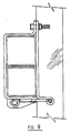
- a scaffolding module 10 according to a preferred form of the present invention.
- the module in this instance is of generally rectangular form and includes four upright preferably hollow rectangular cross sectioned support members 11 at the corners thereof which support at their upper end a deck framework 12 which is covered by a sheeting material 13 such as steel sheet or the like.
- a sheeting material 13 such as steel sheet or the like.
- suitable bracing 14 is provided at the upper ends of the support members 11 to provide stability to the module 10.
- the operative rear wall of the module is also closed in by sheeting 15 such as steel sheeting which may be supported by a central bracing member 16 extending between the rear upstanding support members 11.
- Each upstanding support member 11 is provided at its lower end with an adjustable foot assembly 17 each of which may be adjusted to support the module 10 in a required attitude and which are preferably arranged to compensate for variations in or undulations in the surface such as a footpath surface upon which the modules are to be supported.
- each foot assembly 17 may be in the form shown in Figs. 4 and 5 and include a first hollow member 18 telescopically receivable within the lower end of the support member 11 and provided with a plurality of spaced apertures 19 therein which may be aligned with a pair of apertures in the opposite sides of the support member 11 so that a locking pin or member 20 may be passed therethrough so that the hollow member 18 is maintained in a fixed position relative to the end of support member 11.
- This adjustment may be varied by removing the pin 20 and repositioning the hollow member 18 until a further pair of its apertures 19 are aligned with the apertures 20 of the support member 11. This therefor provides for a course adjustment of the length of the support member 11.
- the lower end of the hollow member 18 is provided with an end cap or plate 21 provided with an aperture 22 thereon to receive therethrough the threaded shank 23 of the support foot 24 in the manner illustrated.
- Plate 21 may be provided with a plurality of drainage holes.
- Fine adjustment of the foot 24 is achieved by means of a nut 25 threadely engaged with the shank 23 and normally in abutment with the end cap 21.
- a nut 25 threadely engaged with the shank 23 and normally in abutment with the end cap 21.
- Suitable abutment of the nut 25 with the cap 21 is maintained by means of a spring 26 surrounding the threaded shank 23 internally of the hollow member and interposed between the end cap 21 and an end plate 26 secured to the end of the threaded shank 18.
- the opposite end of the foot 24 is provided with a universal joint so that the foot may adopt any position to cater for variations in the underlying support surface.
- the universal joint comprises an eye 27 at the end of the threaded shank received within a hollow housing 28 secured to a planar mounting foot 29.
- the hollow housing 28 is provided at its opposite sides with respective cut out portions 30 which are so sized and positioned as to captively hold the eye 27 within the hollow housing 28.
- the above described arrangement also permits easy cleaning of the housing 28 after use.
- This joint permits a sufficient degree of universal movement to cater for most variations encountered in the support surface for the gantry.
- other suitable pivotal foot assemblies 17 may be employed for the support members such as a universal ball type joint as shown in Fig. 6.
- the invention also provides a plurality of clamp assemblies which may be used to clamp together respective upright support members 11 of adjacent gantries.
- a suitable clamp assembly 31 for this purpose is shown in Fig. 7 and comprises a pair of hinged parts 32 and 33, one part 32 being of relatively planar form, the other part defining an elongated recess 34 which in use neatly receives a pair of support members 11.
- the respective parts may then be simply held together by bolting.
- the support members may be simply bolted together by means of bolts passing through aligned holes therein.
- clamps 31 ⁇ may also be provided with means for engaging and retaining side rails 32 for the gantries and a suitable form for such retaining means is shown in Figures 8 to 10.
- Normally side rails 32 are attached to a gantry 10 intermediate the ends of the upstanding support members 11 for pedestrian safety purposes and as used in the present instance are preferably of C shape cross-section form.
- the means for engaging and retaining the side rails in this instance are operative to clamp the free flange ends 33 of the C-shaped rails to the upstands 11 and for this purpose the retaining means comprise a pair of jaws 44 pivotably mounted on a support plate 35 forming part of the support member clamp 31 ⁇ and being pivotal from an engaged position shown in Figure 8 to a disengaged position whereby the side rails 32 may be detached.
- means are provided to urge the jaws 44 to an operative retaining attitude and in this instance such means comprise a bolt 36 which is passed through apertures 37 formed in ears 38 comprising extensions of the jaws.
- the bolt 36 may simply be tightened to pivot the ears 38 towards each other and cause corresponding opposite pivotal movement of the jaws 44 to a rail retaining and clamping attitude.
- one of the ears may be provided with a threaded stud which is passed through an aperture 37 in the other ear to be engaged by a nut.
- support plate 35 has welded thereto a tubular section 43 which in use aligns with through apertures 37.
- ears 38 are clamped by bolt 36 in abutting relationship with tubular section 43.
- tubular section 43 the portion of jaws 44 contacting the free flange ends 33 of the C-shaped rails may be angled towards and in some cases past the edge of upstand 11 when the ears 38 are in operative abutment with tubular section 43 to provide additional frictional holding of the C-channel side-rails 32 when operatively engaged.
- the gantry modules may also be provided with detachable top rails 39 which serve as a railing for persons walking or moving about the deck 13.
- the upper ends of the support members 11 may be provided with sockets 40 which may simply receive the spigot ends of upstanding supports 41 for the top rails 39.
- a pair of adjacent top rails 39 may be interconnected by a U-shaped member 42 in the manner shown in Figure 1.
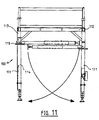
- a gantry module 100 including upstanding support members or legs 111 and roof assembly 112.
- Each leg 111 includes an upper fixed portion 113 and a lower folding portion 114.
- the lower folding portion 114 is hingedly attached to the portion 113 about a hinge 115.
- Hinge 115 is preferably arranged so as to prevent folding portion 114 from folding outwardly from its position of alignment with fixed portion 113.
- the folding portions 114 are illustrated in their operatively folded and unfolded attitudes.
- the folding portions 114 may be suitably secured in their unfolded and folded attitudes.
- a plurality of scaffolding modules 10 may be simply delivered to site with the required course adjustment of the foot assemblies 17 preferably made prior to delivery thereof.
- the modules 10 are arranged in end to end relationship and interconnected by clamps of the type shown in Figure 7 or alternatively connected by bolting whilst fine adjustment of the foot assembly 17 may be carried out by adjustment of the nuts 15.
- the support plates 29 are of course in conventional manner mounted on lengths of timber arranged along say a footpath and secured thereto by any suitable fasteners passed through apertures therein.
- the side rails 32 may be then simply assembled and clamped to the support members 11 and the top rails 39 engaged in the manner described above.
- gantry module described above may be of any physical dimensions and of alternative forms to that described. It will also be realised that many other forms of foot assembly may be employed to provide a pivotal mount to cater for footpath undulations.
Landscapes
- Engineering & Computer Science (AREA)
- Architecture (AREA)
- Mechanical Engineering (AREA)
- Civil Engineering (AREA)
- Structural Engineering (AREA)
- Mutual Connection Of Rods And Tubes (AREA)
Applications Claiming Priority (2)
| Application Number | Priority Date | Filing Date | Title |
|---|---|---|---|
| AU69125/87A AU578176B2 (en) | 1986-02-20 | 1987-02-19 | Modular gantry assemblies providing temporary pedestrian thoroughfares |
| CA000544723A CA1320520C (en) | 1987-02-19 | 1987-08-17 | Scaffolding |
Publications (1)
| Publication Number | Publication Date |
|---|---|
| EP0304518A1 true EP0304518A1 (de) | 1989-03-01 |
Family
ID=25635916
Family Applications (1)
| Application Number | Title | Priority Date | Filing Date |
|---|---|---|---|
| EP87307533A Withdrawn EP0304518A1 (de) | 1987-02-19 | 1987-08-25 | Baugerüst |
Country Status (3)
| Country | Link |
|---|---|
| EP (1) | EP0304518A1 (de) |
| AU (1) | AU578176B2 (de) |
| CA (1) | CA1320520C (de) |
Cited By (2)
| Publication number | Priority date | Publication date | Assignee | Title |
|---|---|---|---|---|
| CN113775213A (zh) * | 2021-10-12 | 2021-12-10 | 安徽谦谨建设有限公司 | 一种房建施工可拆卸式定型防护作业棚 |
| FR3155011A1 (fr) * | 2023-11-02 | 2025-05-09 | Metal Passion | Système modulaire de passerelle piétonne métallique |
Families Citing this family (5)
| Publication number | Priority date | Publication date | Assignee | Title |
|---|---|---|---|---|
| AU621838B2 (en) * | 1987-11-09 | 1992-03-26 | Speedy Gantry Hire Pty. Ltd. | Improvements to scaffolding |
| WO2007132148A2 (en) * | 2006-05-04 | 2007-11-22 | Access Products Limited | Scaffolding |
| CN102191851B (zh) * | 2010-03-18 | 2013-04-24 | 王云剑 | 一种新型支架体系 |
| WO2015158324A1 (de) * | 2014-04-14 | 2015-10-22 | Lars Flint | Unterbaugerüsteinheit, unterbaugerüstsystem und verfahren zum aufbau bzw. abbau einer unterbaugerüsteinheit |
| CN115059280A (zh) * | 2022-08-04 | 2022-09-16 | 中国能源建设集团山西电力建设有限公司 | 通用型h钢立柱上卡接式脚手架平台支撑结构的构建方法 |
Citations (7)
| Publication number | Priority date | Publication date | Assignee | Title |
|---|---|---|---|---|
| DE1827584U (de) * | 1960-12-24 | 1961-03-02 | Betonbau G M B H | Stahlgeruest fuer bauarbeiten. |
| US3207261A (en) * | 1963-09-27 | 1965-09-21 | Carl E Petersen | Scaffold |
| DE1929739A1 (de) * | 1968-06-12 | 1969-12-18 | Anvar | Vorrichtung zur optischen Konzentration mit maximaler Beleuchtungsstaerke |
| DE2109088A1 (de) * | 1971-02-25 | 1972-09-21 | Holzmann Philipp Ag | Raeumliches Bauelement zur Bildung von Trag- und Stuetzwerken aller Art |
| DE2131320A1 (de) * | 1971-06-24 | 1973-01-11 | Jonny Janus | Geruest fuer allgemeine bau-putzer-malerarbeiten |
| DE2314023A1 (de) * | 1972-06-01 | 1973-12-06 | Industrialisation Du Materiel | Dreifuss zur unterstuetzung einer verschalung |
| DE8100831U1 (de) * | 1981-01-16 | 1981-06-19 | Schwechheimer, Jürgen, 4053 Jüchen | Arbeitsplattform |
Family Cites Families (3)
| Publication number | Priority date | Publication date | Assignee | Title |
|---|---|---|---|---|
| US2462429A (en) * | 1945-08-30 | 1949-02-22 | Sachs Milton | Scaffold |
| US2593122A (en) * | 1946-12-27 | 1952-04-15 | Baker Roos Inc | Scaffold |
| DE1260116B (de) * | 1960-07-08 | 1968-02-01 | Thyssen Roehren & Roheisen | Loesbare Verbindung von horizontalen Laengsriegelelementen, insbesondere von Geruestbuehnenrahmen, an die Stiele eines Geruests |
-
1987
- 1987-02-19 AU AU69125/87A patent/AU578176B2/en not_active Revoked
- 1987-08-17 CA CA000544723A patent/CA1320520C/en not_active Expired - Fee Related
- 1987-08-25 EP EP87307533A patent/EP0304518A1/de not_active Withdrawn
Patent Citations (7)
| Publication number | Priority date | Publication date | Assignee | Title |
|---|---|---|---|---|
| DE1827584U (de) * | 1960-12-24 | 1961-03-02 | Betonbau G M B H | Stahlgeruest fuer bauarbeiten. |
| US3207261A (en) * | 1963-09-27 | 1965-09-21 | Carl E Petersen | Scaffold |
| DE1929739A1 (de) * | 1968-06-12 | 1969-12-18 | Anvar | Vorrichtung zur optischen Konzentration mit maximaler Beleuchtungsstaerke |
| DE2109088A1 (de) * | 1971-02-25 | 1972-09-21 | Holzmann Philipp Ag | Raeumliches Bauelement zur Bildung von Trag- und Stuetzwerken aller Art |
| DE2131320A1 (de) * | 1971-06-24 | 1973-01-11 | Jonny Janus | Geruest fuer allgemeine bau-putzer-malerarbeiten |
| DE2314023A1 (de) * | 1972-06-01 | 1973-12-06 | Industrialisation Du Materiel | Dreifuss zur unterstuetzung einer verschalung |
| DE8100831U1 (de) * | 1981-01-16 | 1981-06-19 | Schwechheimer, Jürgen, 4053 Jüchen | Arbeitsplattform |
Cited By (3)
| Publication number | Priority date | Publication date | Assignee | Title |
|---|---|---|---|---|
| CN113775213A (zh) * | 2021-10-12 | 2021-12-10 | 安徽谦谨建设有限公司 | 一种房建施工可拆卸式定型防护作业棚 |
| CN113775213B (zh) * | 2021-10-12 | 2022-11-04 | 安徽谦谨建设有限公司 | 一种房建施工可拆卸式定型防护作业棚 |
| FR3155011A1 (fr) * | 2023-11-02 | 2025-05-09 | Metal Passion | Système modulaire de passerelle piétonne métallique |
Also Published As
| Publication number | Publication date |
|---|---|
| AU578176B2 (en) | 1988-10-13 |
| AU6912587A (en) | 1987-08-27 |
| CA1320520C (en) | 1993-07-20 |
Similar Documents
| Publication | Publication Date | Title |
|---|---|---|
| US5127492A (en) | Scaffolding | |
| US10968644B2 (en) | Kit for erecting a platform | |
| US20240368903A1 (en) | Erected platform | |
| US4972924A (en) | Modular scaffolding gantry | |
| US5269394A (en) | Universal bracket apparatus for attaching toe boards to scaffolds | |
| US20020157900A1 (en) | Foldable scaffold device | |
| US4773506A (en) | Scaffolding module and method of erecting same | |
| US6789649B2 (en) | Anchor clamp | |
| US4673060A (en) | Foldable scaffold and method | |
| US3908793A (en) | Adjustable metal scaffold | |
| US4858726A (en) | Scaffolding module and method erecting same | |
| EP0304518A1 (de) | Baugerüst | |
| GB2113285A (en) | Roof scaffolding | |
| AU2017100073A4 (en) | Hoarding assembly | |
| CN1031576A (zh) | 门型脚手架的改进 | |
| GB1592372A (en) | Collapsible builders stage | |
| CA2445024A1 (en) | Horizontal support member for tube and clamp scaffold system | |
| US4296573A (en) | Audience control barrier | |
| AU599144B2 (en) | Scaffold base clamp | |
| CA1331767C (en) | Scaffolding clamp and pallet | |
| AU721823B2 (en) | Support structure for roof safety system | |
| AU758121B2 (en) | Scaffolding method and apparatus | |
| AU722181B2 (en) | Fencing arrangement | |
| JP3086838B2 (ja) | 足場ユニット | |
| GB2417752A (en) | Platform for use in erecting scaffolding |
Legal Events
| Date | Code | Title | Description |
|---|---|---|---|
| PUAI | Public reference made under article 153(3) epc to a published international application that has entered the european phase |
Free format text: ORIGINAL CODE: 0009012 |
|
| AK | Designated contracting states |
Kind code of ref document: A1 Designated state(s): BE DE FR GB IT NL SE |
|
| RIN1 | Information on inventor provided before grant (corrected) |
Inventor name: NIELSEN, DENIEL MATHAIRS |
|
| 17P | Request for examination filed |
Effective date: 19890901 |
|
| 17Q | First examination report despatched |
Effective date: 19910417 |
|
| STAA | Information on the status of an ep patent application or granted ep patent |
Free format text: STATUS: THE APPLICATION IS DEEMED TO BE WITHDRAWN |
|
| 18D | Application deemed to be withdrawn |
Effective date: 19930915 |