EP0304164B1 - Leak detector - Google Patents
Leak detector Download PDFInfo
- Publication number
- EP0304164B1 EP0304164B1 EP88306575A EP88306575A EP0304164B1 EP 0304164 B1 EP0304164 B1 EP 0304164B1 EP 88306575 A EP88306575 A EP 88306575A EP 88306575 A EP88306575 A EP 88306575A EP 0304164 B1 EP0304164 B1 EP 0304164B1
- Authority
- EP
- European Patent Office
- Prior art keywords
- bottle
- light
- sealing surface
- light source
- finish
- Prior art date
- Legal status (The legal status is an assumption and is not a legal conclusion. Google has not performed a legal analysis and makes no representation as to the accuracy of the status listed.)
- Expired - Lifetime
Links
- 238000007789 sealing Methods 0.000 claims description 54
- 238000007689 inspection Methods 0.000 description 22
- 238000012360 testing method Methods 0.000 description 14
- 230000007704 transition Effects 0.000 description 12
- 238000005286 illumination Methods 0.000 description 7
- 230000007547 defect Effects 0.000 description 6
- 230000003750 conditioning effect Effects 0.000 description 3
- 238000000034 method Methods 0.000 description 3
- 230000003287 optical effect Effects 0.000 description 3
- 230000008569 process Effects 0.000 description 3
- 230000002950 deficient Effects 0.000 description 2
- 238000010586 diagram Methods 0.000 description 2
- 230000007246 mechanism Effects 0.000 description 2
- 230000004044 response Effects 0.000 description 2
- 238000006424 Flood reaction Methods 0.000 description 1
- 230000004913 activation Effects 0.000 description 1
- 238000004364 calculation method Methods 0.000 description 1
- 238000004590 computer program Methods 0.000 description 1
- 238000010276 construction Methods 0.000 description 1
- 238000001514 detection method Methods 0.000 description 1
- 230000006870 function Effects 0.000 description 1
- 239000011521 glass Substances 0.000 description 1
- 238000002347 injection Methods 0.000 description 1
- 239000007924 injection Substances 0.000 description 1
- 230000010354 integration Effects 0.000 description 1
- 239000000463 material Substances 0.000 description 1
- 238000012986 modification Methods 0.000 description 1
- 230000004048 modification Effects 0.000 description 1
- 230000010287 polarization Effects 0.000 description 1
- 238000012545 processing Methods 0.000 description 1
- 230000009467 reduction Effects 0.000 description 1
- 230000000717 retained effect Effects 0.000 description 1
- 238000012552 review Methods 0.000 description 1
- 238000006467 substitution reaction Methods 0.000 description 1
- 210000003813 thumb Anatomy 0.000 description 1
Images


Classifications
-
- B—PERFORMING OPERATIONS; TRANSPORTING
- B07—SEPARATING SOLIDS FROM SOLIDS; SORTING
- B07C—POSTAL SORTING; SORTING INDIVIDUAL ARTICLES, OR BULK MATERIAL FIT TO BE SORTED PIECE-MEAL, e.g. BY PICKING
- B07C5/00—Sorting according to a characteristic or feature of the articles or material being sorted, e.g. by control effected by devices which detect or measure such characteristic or feature; Sorting by manually actuated devices, e.g. switches
- B07C5/34—Sorting according to other particular properties
- B07C5/3404—Sorting according to other particular properties according to properties of containers or receptacles, e.g. rigidity, leaks, fill-level
- B07C5/3408—Sorting according to other particular properties according to properties of containers or receptacles, e.g. rigidity, leaks, fill-level for bottles, jars or other glassware
-
- G—PHYSICS
- G01—MEASURING; TESTING
- G01N—INVESTIGATING OR ANALYSING MATERIALS BY DETERMINING THEIR CHEMICAL OR PHYSICAL PROPERTIES
- G01N21/00—Investigating or analysing materials by the use of optical means, i.e. using sub-millimetre waves, infrared, visible or ultraviolet light
- G01N21/84—Systems specially adapted for particular applications
- G01N21/88—Investigating the presence of flaws or contamination
- G01N21/90—Investigating the presence of flaws or contamination in a container or its contents
- G01N21/9054—Inspection of sealing surface and container finish
-
- G—PHYSICS
- G01—MEASURING; TESTING
- G01N—INVESTIGATING OR ANALYSING MATERIALS BY DETERMINING THEIR CHEMICAL OR PHYSICAL PROPERTIES
- G01N21/00—Investigating or analysing materials by the use of optical means, i.e. using sub-millimetre waves, infrared, visible or ultraviolet light
- G01N21/84—Systems specially adapted for particular applications
- G01N21/88—Investigating the presence of flaws or contamination
- G01N21/90—Investigating the presence of flaws or contamination in a container or its contents
- G01N21/9072—Investigating the presence of flaws or contamination in a container or its contents with illumination or detection from inside the container
Definitions
- the invention relates generally to container inspection apparatus and deals more particularly with an apparatus for testing the sealability of the mouth of a container.
- a dip is a narrow depression in the bottle mouth and a saddle is a wide depression.
- a wide variety of finish leak detectors were previously known such as those disclosed in U. S. Patents 3,496,761 and 4,490,800. These detectors inspect the sealing surface of a bottle which is fed by a conveyor or auger screw to an inspection site located beneath the detector.
- the detector of U.S. Patent No. 3,496,761 includes a test fitting which is lowered into engagement with the mouth of the bottle at the inspection site and forms an air-tight seal if the bottle mouth is properly formed - smooth, flat and generally horizontal; otherwise, a leak results.
- the sealability of the bottle mouth by the test fitting mimics the sealability of the bottle mouth by a cap or other type of commercial seal.
- U. S. Patent 3,555,980 to Mathias discloses another type of finish leak detection apparatus.
- the apparatus illuminates the rim of a bottle with a beam of radiant energy which is polarized so that it has an electric vector perpendicular to the top surface of the container.
- the container is rotated relative to the beam during inspection.
- Certain types of defects reflect a portion of the beam upwardly into a sensor which has its line of vision forming Brewster's angle with the direction of the beam. Because of the polarization and the angular relation, a defect makes a substantial reduction in the amount of radiant energy transmitted into the container.
- U.S. Patent 3,880,750 to Butler discloses another optical apparatus for inspecting the sealing surface of a glass container in which a light source focuses a thin line of light across the rim. A light sensor receives a deflection of this light from the rim to provide a reference level. A defect in the rim causes a rise or fall in the received light.
- U. S. Patent 4,026,414 to Ellinger discloses another optical apparatus for testing the sealing surface of a container in which a light sensing head made up of a mosaic of 30-40 light sensors in the form of a circular ring is supported above a bottle being inspected.
- a light source provides a beam through the central aperture which floods the mouth of the bottle and light is reflected upwardly from the bottle rim to the various sensors.
- DE-A-3 631 973 discloses an apparatus for inspecting the sealing surface of a vertically standing bottle, having a mouth portion at the top thereof, in which a circular source whose axis coincides with that of the bottle is positioned vertically above said upright bottle and a circular reflector is positioned concentrically vertically above said circular source. Light reflected from the sealing surface of said bottle is detected by a video camera located at the centre of the circular source and a data processing apparatus is used to compare the detected light with that of a standard picture.
- a general object of the present invention is to provide a detector to sense the sealability of a container mouth which detector is reliable and accurate and provides a high throughput.
- the invention resides in an apparatus for inspecting the sealing surface of a container for dips, saddles and lean. While the container is rotated, a beam of light is projected above and through a finish portion of said container.
- an optical detector detects the height of the sealing surface by detecting the location of a minimum in the light beam. Dips in the height indicate dips or saddles.
- an opaque bearing member is lowered onto the sealing surface in the path of the light beam to provide a reference indicative of the prevailing height of the sealing surface. Light passing beneath the underside of the bearing member and above the sealing surface indicates a dip or saddle.
- Figure 1 is a perspective view illustrating an inspection system including a finish leak detector embodying the present invention.
- Figure 2 is an enlarged, fragmentary schematic diagram of the finish leak detector of Figure 1.
- Figure 3 is a schematic block diagram of electronic circuitry within the finish leak detector of Figure 1.
- Figure 4 is a graph illustrating the response of a camera within the finish leak detector of Figure 1 during an inspection operation.
- Figure 5 is a flow chart illustrating the operation of a microprocessor within the finish leak detector of Figure 1 during an inspection operation.
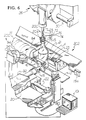
- Figure 6 is a perspective view illustrating another inspection system including another finish leak detector embodying the present invention.
- Figure 7 is an enlarged, fragmentary perspective view of the inspection system of Figure 6 including the other finish leak detector embodying the present invention.
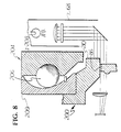
- Figure 8 is an enlarged, fragmentary schematic view of the finish leak detector of Figure 6.
- Figures 9 and 10 are graphs illustrating the responses of a camera within the finish leak detector of Figure 6 during an inspection operation.
- Figure 11 is a flow chart illustrating the operation of a microprocessor within the finish leak detector of Figure 6 during an inspection operation.
- FIG. 1 illustrates an inspection system generally designated 10 which includes a finish leak detector 11 embodying the present invention.
- a container 15 to be inspected is brought to the detector 11 on a linear conveyor 12 of conventional construction.
- the containers are spaced and sequentially moved into a test area or an inspection site by a feed screw 14.
- As the container 15 enters the test area it is engaged by a pair of spaced rollers 16 on a horizontal plunger 18 mounted on a horizontally movable carriage 20.
- Carriage 20 is mounted for movement along the axes of shafts 22 (only one shaft is illustrated). While only one pair of rollers 16 is illustrated, use of two pairs of rollers disposed one above the other may be utilized more efficiently with certain types of containers.
- the rollers 16 contact the container 15 and move it with the carriage 20 while pressing the container 15 against a horizontally moving endless belt 4.
- the belt 4 rotates the container 15 fast enough to make at least one full turn as it passes through the test area.
- the belt 4 extends around guide rollers 5 in housing 21 and is driven by a variable speed motor 17 ( Figure 3) whose speed can be adjusted to provide the required rotation.
- a brake block 23 of a material such as rubber and having a cam face is supported by housing 21. Block 23 and its angled cam face cause the container to lose contact with belt 4 and stop the container from rotating due to the pressure applied by rollers 16. Block 23 is located at the downstream end of the test area.
- the belt 4 can move either opposite the direction of the conveyor movement or with the direction of conveyor movement.
- the preferred direction is with conveyor movement to facilitate the discharge down the conveyor of defective bottles which may fracture during inspection.
- a carriage 26 having a downwardly extending plunger 28 is reciprocally mounted for horizontal movement along shafts 30 (only one shaft is illustrated).
- the plunger 28 is mounted for vertical movement with respect to the carriage 26.
- the carriages 20 and 26 are moved in synchronism through the test area at constant speed in the direction of travel of the conveyor 12 and return at a substantially sinusoidal rate after completion of the inspection of the container 15.
- the mechanism for reciprocating the carriages 20 and 26 in timed relation with the screw 14 as well as the mechanism for moving the plunger 28 downwardly at the beginning of the test area and upwardly at the end of the test area are described in U. S. Patents Nos. 3,387,704 and 3,557,950 to Powers. Further description thereof is unnecessary.
- Each of the plungers 18 and 28 is cammed or spring-biased into contact with the container 15 at the beginning of the stroke of the carriages and biased away from the container at the end of the carriage strokes.
- the finish leak detector 11 comprises an illumination assembly 68 supported by the plunger 28 for vertical reciprocations therewith into and out of the mouth of bottle 15.
- the plunger 18 is extended so that the rollers 16 urge the bottle 15 against the rotation belt 4 to begin rotation of the bottle 15.
- the plunger 28 is lowered such that the illumination assembly 68 is lowered into the mouth of the bottle 15 to the position illustrated in Figures 1 and 2.
- Illumination assembly 68 comprises a light source 70 which may be a simple incandescent light bulb, a lens 72 to collect the light of the source 70 and focus it downwardly toward a mirror 74 (or alternately, a prism) also within the illumination assembly 68.
- the assembly 68 further comprises a diffuser 76 supported between the lens 72 and the mirror 74 to diffuse the light emanating from the source 70 to produce a substantially collimated and uniformly intense light beam 77 which illuminates the mirror 74 over region 80.
- the cross section of the light beam 77 is broad enough and the angle of the mirror 74 is such that the light reflects horizontally as indicated by arrows 84 above and below a sealing surface 86 of the bottle 15.
- the finish leak detector 11 further comprises a camera 100 which is fixedly attached to the carriage 20 by a support 92 for reciprocal movement with the carriage 20 in the direction of and the direction opposite the conveyor 12. Consequently, the camera 100 tracks the bottle 15 at the inspection site.
- the camera 100 comprises a lens 94 which receives the light reflected by the mirror 74, collects it and focuses it upon a vertically oriented, linear array 96 of charge coupled devices, which array is also located within the camera 100.
- the linear array contains 256 pixels which allows for 1/16 inches (1.6 mm) depth to the defect plus or minus 1/16 inches (1.6 mm) tolerance with a resolution of 0.0007 inches (0.00018 mm) per pixel.
- the linear array 96 may comprise a Fairchild CCD111 model line-scan sensor which is also sold under the trademark I-Scan.
- the camera 100 also includes electronics 97 to process the outputs of the charge coupled devices. As described in more detail below, the camera detects the heights of the sealing surface at a multiplicity of points as the bottle is rotated, and deviations such as depressions in such heights indicate sealing surface defects.
- the camera 100 is part of a video processor and control 101 illustrated in Figures 1 and 3 which processor operates from a master clock 102.
- the video processor 101 also includes an exposure timing element 104 which sets an exposure or integration time for the linear array 96. In order not to mix two lines of video information in the linear array 96, the exposure time must be greater than the time necessary to read all the information from the previous line.
- the camera 100 supplies three outputs, video clock, start of scan and binary video, to a serial output circuit 106 which outputs serially analog data indicative of the intensity of the illumination on each of the pixels.
- the analog output of the circuit 106 is fed into a signal conditioning circuit 108, the output of which is illustrated in Figure 4 for one profile of the bottle mouth.
- the "zero-th" pixel of the linear array 96 is the highest one and the 255th pixel is the lowest one according to the orientation of Figure 1.
- pixels 0-255 are illuminated to some degree by the light beam 84 transmitted by the illumination assembly 68.
- Pixels 0-24 are illuminated by a portion of the beam 84 which is entirely above the sealing surface 86 so that the pixels 0-24 receive approximately a maximum intensity level of light and such is indicated by the relatively large height of the graph for the pixels 0-24.
- the intensity of the light received by the pixel 25 is the smallest of the linear array because such pixel is aligned horizontally with the sealing surface 86.
- the pixels 26-255 are located below the level of the sealing surface 86 and receive an intensity level which is substantially greater than the level received by the pixel 25 because the light beam 84 below the sealing surface 86 is transmitted through the finish portion which is generally transparent. Irregularity in the intensity levels observed by the pixels 26-255 may be due to irregularities in the cross-section of the finish portion such as due to threads in the finish.
- Irregularities in the heights of the pixels 0-255 may also be due to upward and downward vibrations. It should be noted that as the bottle 15 is rotated, the video camera 100 continuously outputs the intensity levels experienced by the pixels in the linear array 96, and the height of the sealing surface 86 at the intersection of the light beam 84 is indicated by the position of the pixel which receives the lowest intensity level. For example, if the graph of Figure 4 represents a normal portion of the sealing surface 86, the corresponding graph of the profile of a "dipped" portion would indicate that a higher numbered pixel, that is, a pixel below the 25th one is the one having the lowest intensity level.
- pixel 35 would indicate the lowest intensity level.
- the output of signal conditioning converter 108 is supplied to one input of a comparator 150.
- the other input of the comparator is supplied by a potentiometer 152 to yield a threshold level which is set above the intensity level corresponding to the sealing surface 86 (the height of the intensity bar of the 25th pixel in Figure 4) but less than the other intensity levels of the other pixels (less than the intensity level of the pixel 26). Consequently, the output of the comparator 150 goes low when the signal conditioning circuit 108 inputs to it the intensity level of the pixel corresponding to the height of the sealing surface 86, in the aforesaid example, pixel 25.
- the low level signal output from the comparator 150 is supplied to an input of a microprocessor 156 within the video processor and control 101.
- the microprocessor Upon receipt of the low level signal, the microprocessor reads the output of a counter 160 within the video processor 101 which counter is incremented by the master clock from count zero for each serial output representing the intensity level observed by each of the pixels. Consequently, in the aforesaid example, when the output of the comparator 150 goes low, the counter provides a count of 25 to the microprocessor 156 so that the microprocessor learns the height of the sealing surface 86.
- the serial output circuit 106 and the counter 160 may be provided by a Fairchild Pixel Locator Model CCD1120-02. The serial output circuit also resets the counter via a line 159 after all of the pixels of a scan have been output by the serial output circuit.
- the operation of the microprocessor 156 is illustrated by a flow chart of Figure 5 representing a computer program or firmware within a read-only memory (ROM) 164 within the video processor and control 101.
- the microprocessor starts (step 165) when a presence sensor 71 coupled to the auger 14 is activated, indicative of the arrival of the bottle 15 at the test area. Then the microprocessor periodically reads the input supplied by the output of the comparator 150 (step 166) and when the output goes low, reads the output of the counter 160 as noted above (step 168) and then stores the count in a random access memory (RAM) 170. This count corresponds to the height of the bottle sealing surface.
- RAM random access memory
- the microprocessor continues to monitor the output of the counter and read additional counts until the bottle has been rotated once (step 167) (or alternately, during a longer, predetermined inspection interval). The completion of the rotation is indicated by a shaft encoder on the rotation motor 17. Then, the microprocessor calculates the average count per bottle for the multitude of samples of the bottle, which calculation represents the average height of the sealing surface 86 over 360° (step 169), and stores the average count in the RAM 170. Then, the microprocessor compares each of the counts stored in the RAM 170 to the average count calculated in the step 169 (step 172).
- the microprocessor activates a rejector 184 (step 183) because such count indicates that a portion of the sealing surface 86 is well below the average height, a characteristic of either a dip, a saddle or a leaner. If no such count is less than the average count minus the tolerance, then the step 182 leads to the end step without activation of the rejector 184. This indicates an acceptable sealing surface.
- the aforesaid circuitry and process detect leaning bottles because the sealing surface of a leaning bottle generally leans along with the bottle so that one portion of the sealing surface in the leaning bottle is substantially below the average height.
- the microprocessor can be programmed to distinguish leaning bottles from dips by calculating the number of successive samples having a sealing surface height substantially less than the average. A very large number corresponding to approximately half the finish circumference indicates lean.
- FIGs 6, 7 and 8 illustrate another finish leak detector 200 also embodying the present invention.
- the finish leak detector 200 is adapted to an inspection system 202 which is very similar to the inspection system 10 illustrated in Figure 1 and like reference numerals indicate like components.
- the finish leak detector 200 is also similar to the finish leak detector 11 with like reference numerals indicating like elements.
- the basic differences between the two finish leak detectors are as follows.
- the finish leak detector 200 includes a bearing mounted head 204 which circumferentially surrounds the illumination assembly 68 and bears against the entire sealing surface 86 of the bottle 15.
- the bearing mounted head 204 includes a ball joint comprising a ball bearing 206, an inner race 208 and an outer race 209.
- the inner race 208 is fixedly attached to the plunger 28 so that the socket can seat on the sealing surface 86 despite a limited amount of lean of the sealing surface.
- the bearing mounted head also includes a bearing member 210 which engages the sealing surface 86 and is stationary relative thereto during rotation of the bottle. Consequently, the bearing member 210 rotates relative to the outer race 209 during rotation of the bottle.
- the bearing mounted head serves two functions. It helps to stabilize the bottle 15 against vertical vibrations so that the pixel which corresponds to the height of the sealing surface during each sample is less affected by vibrations. Also, the bearing mounted head provides a reference level indicative of the non-defective or prevailing height portions of the sealing surface 86.
- the intensity level observed by each of the pixels 0-24 located above the sealing surface 86 is zero except for ambient light because the portions of the light beam 84 located above the sealing surface 86 are blocked by the bearing mounted head.
- the pixel 25 located at the level of the sealing surface 86 receives a very small amount of light which is comparable to the amount of light received by the pixel 25 in the example of Figure 4.
- the pixels 26-255 located below the height of the sealing surface 86 receive light which is transmitted through the finish portion of the bottle and the amount of light received by each of the pixels 26-255 in the Figure 9 example is approximately the same as each of the pixels 26-255 in the Figure 4 example.
- the first or lowest numbered pixel which exhibits a significant intensity level represents the height of the undersurface of the bearing mounted head and this height is the normal height or prevailing height of the sealing surface 86.
- the bearing element 210 is not compliant enough to follow the contour of a dip or even a saddle.
- Figure 10 illustrates the intensity graph of a profiled portion of the bottle finish corresponding to a dip 87 (or a saddle).
- the height of the pixel 25 represents the undersurface of the bearing element 210 or the normal or prevailing height of the sealing surface.
- the graph also illustrates that the four pixels below the undersurface of the bearing element 210, pixels 25-28, receive a very high light intensity indicative of a gap beneath the bearing element 210.
- the next pixel down, pixel 29, exhibits the low intensity level associated with the height of the sealing surface at the profile of the sample so that the gap between the undersurface of the bearing element 210 and the sealing surface 86 at this profile is approximately four pixels wide.
- the pixels beneath the pixel 29 receive the light intensities as noted above associated with the column 84 being transmitted through the bottle finish.
- the finish leak detector 200 utilizes the same video camera 100 and the same video processor and control 101, as noted above for the finish leak detector 10 except that the ROM 164 within the finish leak detector 200 contains a slightly different operating program or firmware as illustrated in Figure 11.
- the microprocessor periodically reviews the output of the comparator 150. Whenever the output makes a transition in either polarity (step 220) the microprocessor reads the output of the counter 160 and stores this count and the type of the transition (step 222).
- the microprocessor continues to note counts and transitions until the sample is complete, i.e., when the count reaches 255 (step 223). It should be noted that for the samples in which the profiled portion does not include a dip or a saddle, there is but one transition corresponding to the transition from an approximately zero intensity level pixel to a pixel having an intensity level greater than zero as illustrated in Figure 8.
- a sample is a profiled portion including a dip or saddle
- the microprocessor repeats the steps 220-223 for additional samples or profiles of the bottle finish until one rotation has been completed (step 225).
- the microprocessor subtracts the difference in counts between the first positive going transition and the first negative going transition (step 224) which indicates the gap between the undersurface of the bearing element 210 or prevailing height of the sealing surface and the lowest depth of the sealing surface 86 beneath it in the profiled portion. This is the depth of the dip or saddle, and if it is greater than a tolerance level (step 226) input previously to the microprocessor via the keyboard 180, the microprocessor activates the rejector 184 (step 228), if not, the bottle is determined to have an adequate sealing surface (step 230).
- the bearing mounted head serves as a reference level to gauge the depth of dips or saddles and the performance of the finish leak detector 200 is not substantially affected by vibrations.
- finish leak detectors embodying the present invention have been disclosed.
- numerous modifications and substitutions may be made without deviating from the scope of the invention.
- finish rollers illustrated in the U.S. Patent 3,690,456 to Powers may be utilized in conjunction with the finish leak detector 11 to stabilize the bottle 15 against vibrations; such finish rollers should not be positioned in the path of the light beam 84 and should not otherwise affect the process carried out by the electronic control 158 associated with the finish leak detector 10.
- the finish leak detectors 11 and 200 can also be used to detect raised "bumps" in the sealing surface. Therefore, the invention has been disclosed by way of illustration and not limitation and reference should be made to the following claims to determine the scope of the invention.
Description
- The invention relates generally to container inspection apparatus and deals more particularly with an apparatus for testing the sealability of the mouth of a container.
- Two types of sealing surface defects are dips and saddles. A dip is a narrow depression in the bottle mouth and a saddle is a wide depression.
- A wide variety of finish leak detectors were previously known such as those disclosed in U. S. Patents 3,496,761 and 4,490,800. These detectors inspect the sealing surface of a bottle which is fed by a conveyor or auger screw to an inspection site located beneath the detector. The detector of U.S. Patent No. 3,496,761 includes a test fitting which is lowered into engagement with the mouth of the bottle at the inspection site and forms an air-tight seal if the bottle mouth is properly formed - smooth, flat and generally horizontal; otherwise, a leak results. The sealability of the bottle mouth by the test fitting mimics the sealability of the bottle mouth by a cap or other type of commercial seal.
- In various leak detectors previously known, air is injected into the bottle and pressure is sensed according to a variety of schemes. For example, in U.S. Patent 3,496,761 a metered volume of air is injected into the container by a piston and cylinder assembly which forms a pump. At the conclusion of the discharge stroke of the piston and cylinder assembly, while the test fitting still closes the mouth of the container under test, the air pressure retained in the container is gauged to determine whether an excessive leakage takes place due to imperfections in the container mouth. While this system is effective in detecting flaws in the surface of a bottle mouth, it is limited in the rate at which it can inspect bottles. Moreover, this type of inspection system requires contact with the bottle and injection of air, and the fulfillment of each requirement may contaminate the bottle.
- U. S. Patent 3,555,980 to Mathias discloses another type of finish leak detection apparatus. The apparatus illuminates the rim of a bottle with a beam of radiant energy which is polarized so that it has an electric vector perpendicular to the top surface of the container. The container is rotated relative to the beam during inspection. Certain types of defects reflect a portion of the beam upwardly into a sensor which has its line of vision forming Brewster's angle with the direction of the beam. Because of the polarization and the angular relation, a defect makes a substantial reduction in the amount of radiant energy transmitted into the container.
- U.S. Patent 3,880,750 to Butler discloses another optical apparatus for inspecting the sealing surface of a glass container in which a light source focuses a thin line of light across the rim. A light sensor receives a deflection of this light from the rim to provide a reference level. A defect in the rim causes a rise or fall in the received light.
- U. S. Patent 4,026,414 to Ellinger discloses another optical apparatus for testing the sealing surface of a container in which a light sensing head made up of a mosaic of 30-40 light sensors in the form of a circular ring is supported above a bottle being inspected. A light source provides a beam through the central aperture which floods the mouth of the bottle and light is reflected upwardly from the bottle rim to the various sensors. DE-A-3 631 973 discloses an apparatus for inspecting the sealing surface of a vertically standing bottle, having a mouth portion at the top thereof, in which a circular source whose axis coincides with that of the bottle is positioned vertically above said upright bottle and a circular reflector is positioned concentrically vertically above said circular source. Light reflected from the sealing surface of said bottle is detected by a video camera located at the centre of the circular source and a data processing apparatus is used to compare the detected light with that of a standard picture.
- A general object of the present invention is to provide a detector to sense the sealability of a container mouth which detector is reliable and accurate and provides a high throughput.
- The invention resides in an apparatus for inspecting the sealing surface of a container for dips, saddles and lean. While the container is rotated, a beam of light is projected above and through a finish portion of said container. According to one feature of the invention an optical detector detects the height of the sealing surface by detecting the location of a minimum in the light beam. Dips in the height indicate dips or saddles. According to another feature of the invention, an opaque bearing member is lowered onto the sealing surface in the path of the light beam to provide a reference indicative of the prevailing height of the sealing surface. Light passing beneath the underside of the bearing member and above the sealing surface indicates a dip or saddle.
- Figure 1 is a perspective view illustrating an inspection system including a finish leak detector embodying the present invention.
- Figure 2 is an enlarged, fragmentary schematic diagram of the finish leak detector of Figure 1.
- Figure 3 is a schematic block diagram of electronic circuitry within the finish leak detector of Figure 1.
- Figure 4 is a graph illustrating the response of a camera within the finish leak detector of Figure 1 during an inspection operation.
- Figure 5 is a flow chart illustrating the operation of a microprocessor within the finish leak detector of Figure 1 during an inspection operation.
- Figure 6 is a perspective view illustrating another inspection system including another finish leak detector embodying the present invention.
- Figure 7 is an enlarged, fragmentary perspective view of the inspection system of Figure 6 including the other finish leak detector embodying the present invention.
- Figure 8 is an enlarged, fragmentary schematic view of the finish leak detector of Figure 6.
- Figures 9 and 10 are graphs illustrating the responses of a camera within the finish leak detector of Figure 6 during an inspection operation.
- Figure 11 is a flow chart illustrating the operation of a microprocessor within the finish leak detector of Figure 6 during an inspection operation.
- Figure 1 illustrates an inspection system generally designated 10 which includes a finish leak detector 11 embodying the present invention. A
container 15 to be inspected is brought to the detector 11 on alinear conveyor 12 of conventional construction. The containers are spaced and sequentially moved into a test area or an inspection site by afeed screw 14. As thecontainer 15 enters the test area, it is engaged by a pair of spacedrollers 16 on ahorizontal plunger 18 mounted on a horizontallymovable carriage 20.Carriage 20 is mounted for movement along the axes of shafts 22 (only one shaft is illustrated). While only one pair ofrollers 16 is illustrated, use of two pairs of rollers disposed one above the other may be utilized more efficiently with certain types of containers. - The
rollers 16 contact thecontainer 15 and move it with thecarriage 20 while pressing thecontainer 15 against a horizontally moving endless belt 4. The belt 4 rotates thecontainer 15 fast enough to make at least one full turn as it passes through the test area. The belt 4 extends around guide rollers 5 inhousing 21 and is driven by a variable speed motor 17 (Figure 3) whose speed can be adjusted to provide the required rotation. Abrake block 23 of a material such as rubber and having a cam face is supported byhousing 21.Block 23 and its angled cam face cause the container to lose contact with belt 4 and stop the container from rotating due to the pressure applied byrollers 16.Block 23 is located at the downstream end of the test area. - The belt 4 can move either opposite the direction of the conveyor movement or with the direction of conveyor movement. The preferred direction is with conveyor movement to facilitate the discharge down the conveyor of defective bottles which may fracture during inspection.
- A
carriage 26 having a downwardly extendingplunger 28 is reciprocally mounted for horizontal movement along shafts 30 (only one shaft is illustrated). Theplunger 28 is mounted for vertical movement with respect to thecarriage 26. Thecarriages conveyor 12 and return at a substantially sinusoidal rate after completion of the inspection of thecontainer 15. The mechanism for reciprocating thecarriages screw 14 as well as the mechanism for moving theplunger 28 downwardly at the beginning of the test area and upwardly at the end of the test area are described in U. S. Patents Nos. 3,387,704 and 3,557,950 to Powers. Further description thereof is unnecessary. Each of theplungers container 15 at the beginning of the stroke of the carriages and biased away from the container at the end of the carriage strokes. - Focusing now on the present invention as illustrated in Figures 1 and 2, the finish leak detector 11 comprises an
illumination assembly 68 supported by theplunger 28 for vertical reciprocations therewith into and out of the mouth ofbottle 15. When thebottle 15 arrives at the inspection site, theplunger 18 is extended so that therollers 16 urge thebottle 15 against the rotation belt 4 to begin rotation of thebottle 15. Simultaneously, theplunger 28 is lowered such that theillumination assembly 68 is lowered into the mouth of thebottle 15 to the position illustrated in Figures 1 and 2.Illumination assembly 68 comprises alight source 70 which may be a simple incandescent light bulb, alens 72 to collect the light of thesource 70 and focus it downwardly toward a mirror 74 (or alternately, a prism) also within theillumination assembly 68. Theassembly 68 further comprises adiffuser 76 supported between thelens 72 and themirror 74 to diffuse the light emanating from thesource 70 to produce a substantially collimated and uniformlyintense light beam 77 which illuminates themirror 74 overregion 80. The cross section of thelight beam 77 is broad enough and the angle of themirror 74 is such that the light reflects horizontally as indicated byarrows 84 above and below a sealingsurface 86 of thebottle 15. - The finish leak detector 11 further comprises a
camera 100 which is fixedly attached to thecarriage 20 by asupport 92 for reciprocal movement with thecarriage 20 in the direction of and the direction opposite theconveyor 12. Consequently, thecamera 100 tracks thebottle 15 at the inspection site. Thecamera 100 comprises alens 94 which receives the light reflected by themirror 74, collects it and focuses it upon a vertically oriented,linear array 96 of charge coupled devices, which array is also located within thecamera 100. By way of example, the linear array contains 256 pixels which allows for 1/16 inches (1.6 mm) depth to the defect plus or minus 1/16 inches (1.6 mm) tolerance with a resolution of 0.0007 inches (0.00018 mm) per pixel. Also by way of example, thelinear array 96 may comprise a Fairchild CCD111 model line-scan sensor which is also sold under the trademark I-Scan. Thecamera 100 also includeselectronics 97 to process the outputs of the charge coupled devices. As described in more detail below, the camera detects the heights of the sealing surface at a multiplicity of points as the bottle is rotated, and deviations such as depressions in such heights indicate sealing surface defects. - The
camera 100 is part of a video processor andcontrol 101 illustrated in Figures 1 and 3 which processor operates from amaster clock 102. Thevideo processor 101 also includes anexposure timing element 104 which sets an exposure or integration time for thelinear array 96. In order not to mix two lines of video information in thelinear array 96, the exposure time must be greater than the time necessary to read all the information from the previous line. Thecamera 100 supplies three outputs, video clock, start of scan and binary video, to aserial output circuit 106 which outputs serially analog data indicative of the intensity of the illumination on each of the pixels. The analog output of thecircuit 106 is fed into asignal conditioning circuit 108, the output of which is illustrated in Figure 4 for one profile of the bottle mouth. In the illustrated embodiment, the "zero-th" pixel of thelinear array 96 is the highest one and the 255th pixel is the lowest one according to the orientation of Figure 1. As further illustrated in Figure 4, pixels 0-255 are illuminated to some degree by thelight beam 84 transmitted by theillumination assembly 68. Pixels 0-24 are illuminated by a portion of thebeam 84 which is entirely above the sealingsurface 86 so that the pixels 0-24 receive approximately a maximum intensity level of light and such is indicated by the relatively large height of the graph for the pixels 0-24. The intensity of the light received by thepixel 25 is the smallest of the linear array because such pixel is aligned horizontally with the sealingsurface 86. Consequently, light transmitted at that level toward thepixel 25 is reflected by thesurface 86 away from thepixel 25 due to either minor irregularities to the sealingsurface 86 or lack of parallel between the sealingsurface 86 and thebeam 84 such that the light beam reflects from the sealingsurface 86 according to Snell's law. The pixels 26-255 are located below the level of the sealingsurface 86 and receive an intensity level which is substantially greater than the level received by thepixel 25 because thelight beam 84 below the sealingsurface 86 is transmitted through the finish portion which is generally transparent. Irregularity in the intensity levels observed by the pixels 26-255 may be due to irregularities in the cross-section of the finish portion such as due to threads in the finish. Irregularities in the heights of the pixels 0-255 may also be due to upward and downward vibrations. It should be noted that as thebottle 15 is rotated, thevideo camera 100 continuously outputs the intensity levels experienced by the pixels in thelinear array 96, and the height of the sealingsurface 86 at the intersection of thelight beam 84 is indicated by the position of the pixel which receives the lowest intensity level. For example, if the graph of Figure 4 represents a normal portion of the sealingsurface 86, the corresponding graph of the profile of a "dipped" portion would indicate that a higher numbered pixel, that is, a pixel below the 25th one is the one having the lowest intensity level. By way of example, if the resolution for a pixel is 0.0007 inches (0.00018 mm) and the bottle was in a position such that thebeam 84 passes through the bottle finish at the lowest depth of a 0.007 inch (0.0018 mm) dip, then pixel 35 would indicate the lowest intensity level. - The output of
signal conditioning converter 108 is supplied to one input of acomparator 150. The other input of the comparator is supplied by apotentiometer 152 to yield a threshold level which is set above the intensity level corresponding to the sealing surface 86 (the height of the intensity bar of the 25th pixel in Figure 4) but less than the other intensity levels of the other pixels (less than the intensity level of the pixel 26). Consequently, the output of thecomparator 150 goes low when thesignal conditioning circuit 108 inputs to it the intensity level of the pixel corresponding to the height of the sealingsurface 86, in the aforesaid example,pixel 25. The low level signal output from thecomparator 150 is supplied to an input of amicroprocessor 156 within the video processor andcontrol 101. Upon receipt of the low level signal, the microprocessor reads the output of a counter 160 within thevideo processor 101 which counter is incremented by the master clock from count zero for each serial output representing the intensity level observed by each of the pixels. Consequently, in the aforesaid example, when the output of thecomparator 150 goes low, the counter provides a count of 25 to themicroprocessor 156 so that the microprocessor learns the height of the sealingsurface 86. By way of example, theserial output circuit 106 and the counter 160 may be provided by a Fairchild Pixel Locator Model CCD1120-02. The serial output circuit also resets the counter via aline 159 after all of the pixels of a scan have been output by the serial output circuit. - The operation of the
microprocessor 156 is illustrated by a flow chart of Figure 5 representing a computer program or firmware within a read-only memory (ROM) 164 within the video processor andcontrol 101. The microprocessor starts (step 165) when apresence sensor 71 coupled to theauger 14 is activated, indicative of the arrival of thebottle 15 at the test area. Then the microprocessor periodically reads the input supplied by the output of the comparator 150 (step 166) and when the output goes low, reads the output of the counter 160 as noted above (step 168) and then stores the count in a random access memory (RAM) 170. This count corresponds to the height of the bottle sealing surface. The microprocessor continues to monitor the output of the counter and read additional counts until the bottle has been rotated once (step 167) (or alternately, during a longer, predetermined inspection interval). The completion of the rotation is indicated by a shaft encoder on therotation motor 17. Then, the microprocessor calculates the average count per bottle for the multitude of samples of the bottle, which calculation represents the average height of the sealingsurface 86 over 360° (step 169), and stores the average count in theRAM 170. Then, the microprocessor compares each of the counts stored in theRAM 170 to the average count calculated in the step 169 (step 172). If any of such counts are less than the average count minus a tolerance value, which is entered into the microprocessor via a keyboard 180 (Figure 1) (or alternately via thumb wheel switch, etc.), then the microprocessor activates a rejector 184 (step 183) because such count indicates that a portion of the sealingsurface 86 is well below the average height, a characteristic of either a dip, a saddle or a leaner. If no such count is less than the average count minus the tolerance, then thestep 182 leads to the end step without activation of therejector 184. This indicates an acceptable sealing surface. - It should also be noted that the aforesaid circuitry and process detect leaning bottles because the sealing surface of a leaning bottle generally leans along with the bottle so that one portion of the sealing surface in the leaning bottle is substantially below the average height. If desired, the microprocessor can be programmed to distinguish leaning bottles from dips by calculating the number of successive samples having a sealing surface height substantially less than the average. A very large number corresponding to approximately half the finish circumference indicates lean.
- Figures 6, 7 and 8 illustrate another
finish leak detector 200 also embodying the present invention. Thefinish leak detector 200 is adapted to aninspection system 202 which is very similar to theinspection system 10 illustrated in Figure 1 and like reference numerals indicate like components. Thefinish leak detector 200 is also similar to the finish leak detector 11 with like reference numerals indicating like elements. The basic differences between the two finish leak detectors are as follows. Thefinish leak detector 200 includes a bearing mountedhead 204 which circumferentially surrounds theillumination assembly 68 and bears against theentire sealing surface 86 of thebottle 15. The bearing mountedhead 204 includes a ball joint comprising aball bearing 206, aninner race 208 and anouter race 209. Theinner race 208 is fixedly attached to theplunger 28 so that the socket can seat on the sealingsurface 86 despite a limited amount of lean of the sealing surface. The bearing mounted head also includes a bearingmember 210 which engages the sealingsurface 86 and is stationary relative thereto during rotation of the bottle. Consequently, the bearingmember 210 rotates relative to theouter race 209 during rotation of the bottle. The bearing mounted head serves two functions. It helps to stabilize thebottle 15 against vertical vibrations so that the pixel which corresponds to the height of the sealing surface during each sample is less affected by vibrations. Also, the bearing mounted head provides a reference level indicative of the non-defective or prevailing height portions of the sealingsurface 86. As illustrated by the graph of Figure 9 which represents a profiled portion of the bottle mouth which is normal, and in fact corresponds to the profiled portion of Figure 4, the intensity level observed by each of the pixels 0-24 located above the sealingsurface 86 is zero except for ambient light because the portions of thelight beam 84 located above the sealingsurface 86 are blocked by the bearing mounted head. Thepixel 25 located at the level of the sealingsurface 86 receives a very small amount of light which is comparable to the amount of light received by thepixel 25 in the example of Figure 4. The pixels 26-255 located below the height of the sealingsurface 86 receive light which is transmitted through the finish portion of the bottle and the amount of light received by each of the pixels 26-255 in the Figure 9 example is approximately the same as each of the pixels 26-255 in the Figure 4 example. As illustrated in Figure 9, the first or lowest numbered pixel which exhibits a significant intensity level represents the height of the undersurface of the bearing mounted head and this height is the normal height or prevailing height of the sealingsurface 86. Thebearing element 210 is not compliant enough to follow the contour of a dip or even a saddle. - Figure 10 illustrates the intensity graph of a profiled portion of the bottle finish corresponding to a dip 87 (or a saddle). For reasons noted above, the height of the
pixel 25 represents the undersurface of thebearing element 210 or the normal or prevailing height of the sealing surface. The graph also illustrates that the four pixels below the undersurface of thebearing element 210, pixels 25-28, receive a very high light intensity indicative of a gap beneath thebearing element 210. The next pixel down,pixel 29, exhibits the low intensity level associated with the height of the sealing surface at the profile of the sample so that the gap between the undersurface of thebearing element 210 and the sealingsurface 86 at this profile is approximately four pixels wide. The pixels beneath thepixel 29 receive the light intensities as noted above associated with thecolumn 84 being transmitted through the bottle finish. Thefinish leak detector 200 utilizes thesame video camera 100 and the same video processor andcontrol 101, as noted above for thefinish leak detector 10 except that theROM 164 within thefinish leak detector 200 contains a slightly different operating program or firmware as illustrated in Figure 11. When the presence sensor indicates that thebottle 15 has arrived at the inspection site (step 165), the microprocessor periodically reviews the output of thecomparator 150. Whenever the output makes a transition in either polarity (step 220) the microprocessor reads the output of the counter 160 and stores this count and the type of the transition (step 222). The microprocessor continues to note counts and transitions until the sample is complete, i.e., when the count reaches 255 (step 223). It should be noted that for the samples in which the profiled portion does not include a dip or a saddle, there is but one transition corresponding to the transition from an approximately zero intensity level pixel to a pixel having an intensity level greater than zero as illustrated in Figure 8. However, where a sample is a profiled portion including a dip or saddle, there will be a first transition corresponding to the transition from a zero intensity pixel to a greater than zero intensity pixel, a second transition from a high intensity pixel to a very low intensity pixel corresponding to the height of the sealing surface, and a third transition corresponding to the transition from the very low intensity level pixel of the sealing surface to the relatively high intensity level pixel below. The microprocessor repeats the steps 220-223 for additional samples or profiles of the bottle finish until one rotation has been completed (step 225). - Next, the microprocessor subtracts the difference in counts between the first positive going transition and the first negative going transition (step 224) which indicates the gap between the undersurface of the
bearing element 210 or prevailing height of the sealing surface and the lowest depth of the sealingsurface 86 beneath it in the profiled portion. This is the depth of the dip or saddle, and if it is greater than a tolerance level (step 226) input previously to the microprocessor via thekeyboard 180, the microprocessor activates the rejector 184 (step 228), if not, the bottle is determined to have an adequate sealing surface (step 230). - Thus, the bearing mounted head serves as a reference level to gauge the depth of dips or saddles and the performance of the
finish leak detector 200 is not substantially affected by vibrations. - By the foregoing, finish leak detectors embodying the present invention have been disclosed. However, numerous modifications and substitutions may be made without deviating from the scope of the invention. For example, if desired, finish rollers illustrated in the U.S. Patent 3,690,456 to Powers may be utilized in conjunction with the finish leak detector 11 to stabilize the
bottle 15 against vibrations; such finish rollers should not be positioned in the path of thelight beam 84 and should not otherwise affect the process carried out by the electronic control 158 associated with thefinish leak detector 10. Also, thefinish leak detectors 11 and 200 can also be used to detect raised "bumps" in the sealing surface. Therefore, the invention has been disclosed by way of illustration and not limitation and reference should be made to the following claims to determine the scope of the invention.
Claims (4)
- An apparatus for inspecting the sealing surface of a vertically standing bottle having a mouth portion at the top thereof comprising
means for horizontally projecting a collimated and uniformly intense light beam having a selected vertical height including
light source means (70, 72, 76) for producing a vertically downwardly directed substantially collimated and uniformly intense light beam (77) and
mirror means (74) having a selected size and being supported at a predetermined angle for reflecting said light beam (77) as a horizontal substantially collimated and uniformly intense light beam (84) having a selected vertical height,
means (28) for downwardly vertically displacing said mirror means (74) from a location vertically above the bottle to be inspected to a position whereat a portion of said mirror means (74) is located within the bottle whereby a portion of said horizontal light beam will pass through one wall of the bottle and the remaining portion will pass above the bottle,
means (96) outside of the bottle for receiving said horizontal collimated beam,
means (4) for rotating the bottle so that said receiving means will receive said horizontal beam as it passes through horizontally continuous portions of the top of the bottle, and
means (97) for comparing the received light beam with a standard as the bottle is rotated to identify an imperfection in the top surface of the bottle finish. - An apparatus according to claim 1 wherein said light source means comprises a light source (70).
- An apparatus according to claim 2 wherein said light source means further comprising lens means (72) for collecting the light from said light source (70) and focusing the collected light toward said mirror means (74).
- An apparatus according to claim 3, wherein said light source means further comprises means (76) for diffusing the focused light into a collimated and uniformly intense beam of light.
Applications Claiming Priority (2)
| Application Number | Priority Date | Filing Date | Title |
|---|---|---|---|
| US60701 | 1987-07-21 | ||
| US07/060,701 US4786801A (en) | 1987-07-21 | 1987-07-21 | Finish Leak Detector having vertically movable light source |
Publications (3)
| Publication Number | Publication Date |
|---|---|
| EP0304164A2 EP0304164A2 (en) | 1989-02-22 |
| EP0304164A3 EP0304164A3 (en) | 1990-08-29 |
| EP0304164B1 true EP0304164B1 (en) | 1993-03-17 |
Family
ID=22031225
Family Applications (1)
| Application Number | Title | Priority Date | Filing Date |
|---|---|---|---|
| EP88306575A Expired - Lifetime EP0304164B1 (en) | 1987-07-21 | 1988-07-19 | Leak detector |
Country Status (7)
| Country | Link |
|---|---|
| US (1) | US4786801A (en) |
| EP (1) | EP0304164B1 (en) |
| JP (1) | JPH01107140A (en) |
| AU (1) | AU596936B2 (en) |
| BR (1) | BR8803998A (en) |
| DE (1) | DE3879319T2 (en) |
| MX (1) | MX165154B (en) |
Families Citing this family (21)
| Publication number | Priority date | Publication date | Assignee | Title |
|---|---|---|---|---|
| US4924107A (en) * | 1988-10-07 | 1990-05-08 | Ball Corporation | System for inspecting the inside surfaces of a container for defects and method therefor |
| US5126556A (en) * | 1989-12-04 | 1992-06-30 | Coors Brewing Company | Bottle thread imaging apparatus having a light seal means between the light assembly means and the thread |
| US5085515A (en) * | 1990-02-08 | 1992-02-04 | Mitsubishi Metal Corporation | Method and apparatus for inspecting quality of manufactured articles |
| CH683566A5 (en) * | 1991-06-14 | 1994-03-31 | Strausak Ag | Method and apparatus for measuring bodies, in particular containers by means of an optical, non-focusing multibeam arrangement. |
| DE4214958C2 (en) * | 1992-05-11 | 1994-06-09 | Kronseder Maschf Krones | Continuous inspection machine for vessels |
| US5280170A (en) * | 1992-12-22 | 1994-01-18 | Emhart Glass Machinery Investments Inc. | Machine for inspecting the shape of a container having a two dimensional camera for viewing the shadow of the projection of the container |
| GB2288016B (en) * | 1994-03-31 | 1998-05-13 | Tomra Systems As | Device for generating,detecting and recognizing a contour image of a liquid container |
| US5610391A (en) * | 1994-08-25 | 1997-03-11 | Owens-Brockway Glass Container Inc. | Optical inspection of container finish dimensional parameters |
| US6046462A (en) * | 1997-12-16 | 2000-04-04 | Eastman Kodak Company | Method and apparatus for determining orientation of parts resting on a flat surface |
| US5955740A (en) * | 1997-12-16 | 1999-09-21 | Eastman Kodak Company | Inspection method and apparatus for determining the side-up orientation of an object resting on a flat surface |
| US6172748B1 (en) | 1998-12-28 | 2001-01-09 | Applied Vision | Machine vision system and method for non-contact container inspection |
| US6525333B1 (en) | 2000-07-18 | 2003-02-25 | Intelligent Machine Concepts, L.L.C. | System and method for inspecting containers with openings with pipeline image processing |
| KR20020063729A (en) * | 2001-01-30 | 2002-08-05 | 사단법인 고등기술연구원 연구조합 | Apparatus for detecting a fault in glass using a spreading panel |
| JP4261221B2 (en) * | 2003-03-05 | 2009-04-30 | 大日本印刷株式会社 | Packaging inspection method and inspection device |
| US7243787B2 (en) | 2003-03-26 | 2007-07-17 | Nipro Corporation | Medicine bag |
| US7010863B1 (en) * | 2004-01-26 | 2006-03-14 | Owens-Brockway Glass Container Inc. | Optical inspection apparatus and method for inspecting container lean |
| US8429989B2 (en) | 2008-10-18 | 2013-04-30 | Emhart Glass S.A. | Modular apparatus and method for rotating glass containers and the like |
| CA2772494A1 (en) * | 2009-09-18 | 2011-03-24 | Sanofi-Aventis Deutschland Gmbh | Arrangement for determining a longitudinal position of a stopper |
| JP6033041B2 (en) * | 2012-10-31 | 2016-11-30 | 株式会社オハラ | Automatic quality inspection device for optical glass base material and automatic quality inspection method for optical glass base material |
| JP5724069B2 (en) * | 2013-07-17 | 2015-05-27 | キリンテクノシステム株式会社 | Container inspection equipment |
| CN111167743B (en) * | 2019-12-27 | 2023-11-07 | 四川省民众日化有限公司 | Container group positioning and leak detection device and method |
Family Cites Families (17)
| Publication number | Priority date | Publication date | Assignee | Title |
|---|---|---|---|---|
| US3089594A (en) * | 1960-06-13 | 1963-05-14 | Owens Illinois Glass Co | Shape and height detection |
| US3880750A (en) * | 1974-06-06 | 1975-04-29 | Owens Illinois Inc | Sealing surface gauge |
| DE2501975A1 (en) * | 1975-01-18 | 1976-07-22 | Kronseder Hermann | DEVICE FOR CHECKING RESERVOIR COVERS FOR DAMAGE |
| JPS5520123A (en) * | 1978-07-17 | 1980-02-13 | Nippon Pirooburotsuku Seizou K | Crack detector for bottle head |
| DE3114285C2 (en) * | 1981-04-09 | 1983-05-19 | Fa. Hermann Heye, 3063 Obernkirchen | Testing device for the detection of muzzle defects in glass objects |
| JPS5821146A (en) * | 1981-07-30 | 1983-02-07 | Kirin Brewery Co Ltd | Method and device for inspection of defect |
| US4490800A (en) * | 1981-12-14 | 1984-12-25 | Powers Manufacturing, Inc. | Dual head gauger apparatus with automatic adjustment for pressure variation |
| US4488648A (en) * | 1982-05-06 | 1984-12-18 | Powers Manufacturing, Inc. | Flaw detector |
| JPS60129648A (en) * | 1983-12-17 | 1985-07-10 | Ishizuka Glass Ltd | Apparatus for inspecting shape of bottle mouth part |
| JPS60159637A (en) * | 1984-01-31 | 1985-08-21 | Kirin Brewery Co Ltd | Method and device for defect detection |
| JPS60198438A (en) * | 1984-03-22 | 1985-10-07 | Yukio Saito | Method and device for inspecting defect of glass bottle |
| JPS61107144A (en) * | 1984-10-31 | 1986-05-26 | Kirin Brewery Co Ltd | Method for inspecting container |
| JPS61232195A (en) * | 1985-03-29 | 1986-10-16 | サッポロビール株式会社 | Cap inspection device for bottle mouth |
| JPS6212845A (en) * | 1985-07-10 | 1987-01-21 | Kirin Brewery Co Ltd | Detecting device for defect on screwed port part of bottle |
| US4701612A (en) * | 1985-07-19 | 1987-10-20 | Owens-Illinois, Inc. | Inspection of container finish |
| JPS6269154A (en) * | 1985-09-21 | 1987-03-30 | Hajime Sangyo Kk | Defect inspection instrument for mouth of bottle |
| GB2185101B (en) * | 1985-11-22 | 1989-11-29 | United Glass Ltd | Detection of surface defects in glass containers |
-
1987
- 1987-07-21 US US07/060,701 patent/US4786801A/en not_active Expired - Lifetime
-
1988
- 1988-07-19 EP EP88306575A patent/EP0304164B1/en not_active Expired - Lifetime
- 1988-07-19 DE DE8888306575T patent/DE3879319T2/en not_active Expired - Fee Related
- 1988-07-21 BR BR8803998A patent/BR8803998A/en unknown
- 1988-07-21 MX MX12371A patent/MX165154B/en unknown
- 1988-07-21 JP JP63182786A patent/JPH01107140A/en active Pending
- 1988-07-21 AU AU19265/88A patent/AU596936B2/en not_active Ceased
Also Published As
| Publication number | Publication date |
|---|---|
| AU1926588A (en) | 1989-01-27 |
| EP0304164A2 (en) | 1989-02-22 |
| EP0304164A3 (en) | 1990-08-29 |
| US4786801A (en) | 1988-11-22 |
| DE3879319T2 (en) | 1993-06-24 |
| JPH01107140A (en) | 1989-04-25 |
| DE3879319D1 (en) | 1993-04-22 |
| AU596936B2 (en) | 1990-05-17 |
| MX165154B (en) | 1992-10-29 |
| BR8803998A (en) | 1989-02-28 |
Similar Documents
| Publication | Publication Date | Title |
|---|---|---|
| EP0304164B1 (en) | Leak detector | |
| US6025909A (en) | Container sealing surface area inspection | |
| US5610391A (en) | Optical inspection of container finish dimensional parameters | |
| US4872757A (en) | Optical convex surface profiling and gauging apparatus and method therefor | |
| US4500203A (en) | Method and apparatus for inspecting articles | |
| US5917602A (en) | System and method for image acquisition for inspection of articles on a moving conveyor | |
| US6256095B1 (en) | Container sealing surface area inspection | |
| US4483615A (en) | Method and apparatus for detecting checks in glass tubes | |
| JP3612444B2 (en) | Container inspection apparatus and method using single area array sensor and alternating strobe light source | |
| KR890000604B1 (en) | Inspection method of container finish | |
| CA2146095C (en) | Container sealing surface inspection | |
| JPH03502138A (en) | Article inspection system for analyzing edges and adjacent sides | |
| JPH0248859B2 (en) | ||
| US6903814B1 (en) | Container sealing surface inspection | |
| CA2040918A1 (en) | Inspection of container finish | |
| MXPA99004896A (en) | Inspection of containers through the use of a single area arrangement detector and selected light sources alternativame | |
| MXPA98003794A (en) | Inspection of the superficial sealing area of a recipie |
Legal Events
| Date | Code | Title | Description |
|---|---|---|---|
| PUAI | Public reference made under article 153(3) epc to a published international application that has entered the european phase |
Free format text: ORIGINAL CODE: 0009012 |
|
| AK | Designated contracting states |
Kind code of ref document: A2 Designated state(s): DE FR GB IT |
|
| RAP1 | Party data changed (applicant data changed or rights of an application transferred) |
Owner name: EMHART INDUSTRIES, INC. |
|
| PUAL | Search report despatched |
Free format text: ORIGINAL CODE: 0009013 |
|
| AK | Designated contracting states |
Kind code of ref document: A3 Designated state(s): DE FR GB IT |
|
| 17P | Request for examination filed |
Effective date: 19901012 |
|
| RAP1 | Party data changed (applicant data changed or rights of an application transferred) |
Owner name: EMHART GLASS MACHINERY INC., |
|
| RAP1 | Party data changed (applicant data changed or rights of an application transferred) |
Owner name: EMHART GLASS MACHINERY INVESTMENTS INC. |
|
| 17Q | First examination report despatched |
Effective date: 19920601 |
|
| GRAA | (expected) grant |
Free format text: ORIGINAL CODE: 0009210 |
|
| AK | Designated contracting states |
Kind code of ref document: B1 Designated state(s): DE FR GB IT |
|
| REF | Corresponds to: |
Ref document number: 3879319 Country of ref document: DE Date of ref document: 19930422 |
|
| ET | Fr: translation filed | ||
| ITF | It: translation for a ep patent filed |
Owner name: UFFICIO BREVETTI RICCARDI & C. |
|
| PLBE | No opposition filed within time limit |
Free format text: ORIGINAL CODE: 0009261 |
|
| STAA | Information on the status of an ep patent application or granted ep patent |
Free format text: STATUS: NO OPPOSITION FILED WITHIN TIME LIMIT |
|
| 26N | No opposition filed | ||
| REG | Reference to a national code |
Ref country code: FR Ref legal event code: TP |
|
| PGFP | Annual fee paid to national office [announced via postgrant information from national office to epo] |
Ref country code: FR Payment date: 20010702 Year of fee payment: 14 |
|
| PGFP | Annual fee paid to national office [announced via postgrant information from national office to epo] |
Ref country code: GB Payment date: 20010703 Year of fee payment: 14 Ref country code: DE Payment date: 20010703 Year of fee payment: 14 |
|
| REG | Reference to a national code |
Ref country code: GB Ref legal event code: IF02 |
|
| PG25 | Lapsed in a contracting state [announced via postgrant information from national office to epo] |
Ref country code: GB Free format text: LAPSE BECAUSE OF NON-PAYMENT OF DUE FEES Effective date: 20020719 |
|
| PG25 | Lapsed in a contracting state [announced via postgrant information from national office to epo] |
Ref country code: DE Free format text: LAPSE BECAUSE OF NON-PAYMENT OF DUE FEES Effective date: 20030201 |
|
| GBPC | Gb: european patent ceased through non-payment of renewal fee |
Effective date: 20020719 |
|
| PG25 | Lapsed in a contracting state [announced via postgrant information from national office to epo] |
Ref country code: FR Free format text: LAPSE BECAUSE OF NON-PAYMENT OF DUE FEES Effective date: 20030331 |
|
| REG | Reference to a national code |
Ref country code: FR Ref legal event code: ST |
|
| PG25 | Lapsed in a contracting state [announced via postgrant information from national office to epo] |
Ref country code: IT Free format text: LAPSE BECAUSE OF NON-PAYMENT OF DUE FEES;WARNING: LAPSES OF ITALIAN PATENTS WITH EFFECTIVE DATE BEFORE 2007 MAY HAVE OCCURRED AT ANY TIME BEFORE 2007. THE CORRECT EFFECTIVE DATE MAY BE DIFFERENT FROM THE ONE RECORDED. Effective date: 20050719 |