EP0304080A2 - Off-road vehicle - Google Patents
Off-road vehicle Download PDFInfo
- Publication number
- EP0304080A2 EP0304080A2 EP88113508A EP88113508A EP0304080A2 EP 0304080 A2 EP0304080 A2 EP 0304080A2 EP 88113508 A EP88113508 A EP 88113508A EP 88113508 A EP88113508 A EP 88113508A EP 0304080 A2 EP0304080 A2 EP 0304080A2
- Authority
- EP
- European Patent Office
- Prior art keywords
- fan
- heat exchanger
- engine
- compartment
- air intake
- Prior art date
- Legal status (The legal status is an assumption and is not a legal conclusion. Google has not performed a legal analysis and makes no representation as to the accuracy of the status listed.)
- Granted
Links
- 239000003570 air Substances 0.000 claims abstract description 95
- 239000012080 ambient air Substances 0.000 claims abstract description 22
- 230000008878 coupling Effects 0.000 claims 3
- 238000010168 coupling process Methods 0.000 claims 3
- 238000005859 coupling reaction Methods 0.000 claims 3
- 238000009412 basement excavation Methods 0.000 claims 1
- 230000005540 biological transmission Effects 0.000 description 16
- 238000001816 cooling Methods 0.000 description 15
- 239000000428 dust Substances 0.000 description 7
- 238000004519 manufacturing process Methods 0.000 description 6
- 239000000356 contaminant Substances 0.000 description 5
- 238000006073 displacement reaction Methods 0.000 description 5
- 239000012530 fluid Substances 0.000 description 4
- 238000000034 method Methods 0.000 description 4
- 210000001015 abdomen Anatomy 0.000 description 3
- 239000000463 material Substances 0.000 description 3
- 229910052751 metal Inorganic materials 0.000 description 3
- 239000002184 metal Substances 0.000 description 3
- 229910000831 Steel Inorganic materials 0.000 description 2
- 230000002349 favourable effect Effects 0.000 description 2
- 230000033001 locomotion Effects 0.000 description 2
- 239000007858 starting material Substances 0.000 description 2
- 239000010959 steel Substances 0.000 description 2
- 229910000838 Al alloy Inorganic materials 0.000 description 1
- SNAAJJQQZSMGQD-UHFFFAOYSA-N aluminum magnesium Chemical compound [Mg].[Al] SNAAJJQQZSMGQD-UHFFFAOYSA-N 0.000 description 1
- 230000007423 decrease Effects 0.000 description 1
- 230000003247 decreasing effect Effects 0.000 description 1
- 238000001914 filtration Methods 0.000 description 1
- 239000002828 fuel tank Substances 0.000 description 1
- 230000005484 gravity Effects 0.000 description 1
- 230000001939 inductive effect Effects 0.000 description 1
- 238000012423 maintenance Methods 0.000 description 1
- 230000001681 protective effect Effects 0.000 description 1
- 230000001105 regulatory effect Effects 0.000 description 1
- 238000003466 welding Methods 0.000 description 1
Images


Classifications
-
- B—PERFORMING OPERATIONS; TRANSPORTING
- B60—VEHICLES IN GENERAL
- B60K—ARRANGEMENT OR MOUNTING OF PROPULSION UNITS OR OF TRANSMISSIONS IN VEHICLES; ARRANGEMENT OR MOUNTING OF PLURAL DIVERSE PRIME-MOVERS IN VEHICLES; AUXILIARY DRIVES FOR VEHICLES; INSTRUMENTATION OR DASHBOARDS FOR VEHICLES; ARRANGEMENTS IN CONNECTION WITH COOLING, AIR INTAKE, GAS EXHAUST OR FUEL SUPPLY OF PROPULSION UNITS IN VEHICLES
- B60K11/00—Arrangement in connection with cooling of propulsion units
- B60K11/06—Arrangement in connection with cooling of propulsion units with air cooling
-
- E—FIXED CONSTRUCTIONS
- E02—HYDRAULIC ENGINEERING; FOUNDATIONS; SOIL SHIFTING
- E02F—DREDGING; SOIL-SHIFTING
- E02F9/00—Component parts of dredgers or soil-shifting machines, not restricted to one of the kinds covered by groups E02F3/00 - E02F7/00
- E02F9/08—Superstructures; Supports for superstructures
- E02F9/0858—Arrangement of component parts installed on superstructures not otherwise provided for, e.g. electric components, fenders, air-conditioning units
- E02F9/0866—Engine compartment, e.g. heat exchangers, exhaust filters, cooling devices, silencers, mufflers, position of hydraulic pumps in the engine compartment
-
- B—PERFORMING OPERATIONS; TRANSPORTING
- B60—VEHICLES IN GENERAL
- B60K—ARRANGEMENT OR MOUNTING OF PROPULSION UNITS OR OF TRANSMISSIONS IN VEHICLES; ARRANGEMENT OR MOUNTING OF PLURAL DIVERSE PRIME-MOVERS IN VEHICLES; AUXILIARY DRIVES FOR VEHICLES; INSTRUMENTATION OR DASHBOARDS FOR VEHICLES; ARRANGEMENTS IN CONNECTION WITH COOLING, AIR INTAKE, GAS EXHAUST OR FUEL SUPPLY OF PROPULSION UNITS IN VEHICLES
- B60K11/00—Arrangement in connection with cooling of propulsion units
-
- F—MECHANICAL ENGINEERING; LIGHTING; HEATING; WEAPONS; BLASTING
- F01—MACHINES OR ENGINES IN GENERAL; ENGINE PLANTS IN GENERAL; STEAM ENGINES
- F01P—COOLING OF MACHINES OR ENGINES IN GENERAL; COOLING OF INTERNAL-COMBUSTION ENGINES
- F01P3/00—Liquid cooling
- F01P3/18—Arrangements or mounting of liquid-to-air heat-exchangers
Definitions
- the present invention relates generally to engine cooling systems for skid steer loaders.
- the present invention is a flexible cooling system which can utilize a single fan to draw fresh air through the radiator, and to evacuate dust, debris and engine-heated air from the engine compartment.
- Skid steer loaders are compact, highly maneuverable vehicles which are commonly used in a variety of applications. Maneuverability of skid steer loaders is enhanced by a favorable weight ratio for the weight carried at the front and rear axles during loaded and unloaded conditions. It is desirable to provide as compact a vehicle structure as possible to maximize the efficiency of this weight ratio. Accordingly, known skid steer loaders have an engine compartment located at the rear of the vehicle immediately behind the operator's compartment. Approximately 70% of the vehicle weight thereby overlies the rear axle when the bucket at the front of the vehicle is unloaded.
- skid steer loaders are frequently used in locations where considerable air borne debris, dust and other contaminants are present. Contaminant concentration is typically greatest near the surface on which the loader operates, and decreases at greater distances from the surface. However, the engine compartment in skid steer loaders is usually positioned relatively low on the vehicle, near the surface where contaminant concentration is greatest.
- the engine compartment of a skid steer loader is typically located immediately behind and sometimes extends underneath the operator's compartment. Unless provisions are made to evacuate engine-heated air from within the engine compartment, temperatures within the operator's compartment can become uncomfortable. However, if too much air is evacuated from the engine compartment, contaminants will be drawn in through various randomly located openings. This dust and debris will accumulate within the engine compartment, reduce cooling system efficiency, and result in other problems.
- radiator and oil cooler are mounted between a louvered rear closure and an engine fan.
- the engine fan draws air from outside the vehicle through the radiator and oil cooler.
- cooling systems of this type can provide adequate cooling for the engine, no provision is made for evacuating heated air from within the engine compartment. As a result, the operator's compartment can get hot, providing an uncomfortable working environment for the operator.
- the large mass of air passing through the radiator and oil cooler is drawn from locations near the surface. Dust and debris therefore build up within the engine compartment and reduce cooling system efficiency.
- Another engine cooling system uses a fan driven by a hydraulic motor to pull ambient air through an intake radiator and oil cooler located near the top of the engine compartment. Although less debris is drawn into the engine compartment, this system does nothing to alleviate uncomfortably high temperatures which can develop in the operator's compartment.
- a cooling system which draws ambient air through the radiator and oil cooler, and which evacuates heated air from within the engine compartment, is desired.
- the system should evacuate only sufficient air from the engine compartment to maintain a stable near ambient condition so as to minimize the amount of debris carried into the engine compartment.
- Air drawn through the radiator and oil cooler should be as free of contaminants as possible.
- the system must, of course, be efficient. It should also be flexible enough to be capable of being adapted to a variety of different loader models having differing system demands.
- One embodiment of the present invention is a skid steer loader of the type including a heat exchanger and engine enclosure located behind an operator's compartment.
- An ambient air intake and an exhaust port extend through the enclosure.
- a fan shroud mounted within the enclosure has an enclosure evacuation air intake which opens into the enclosure, a heat exchanger air intake, and an exhaust port communicating with the exhaust port extending through the enclosure.
- An engine and radiator are mounted within the enclosure. The radiator is mounted between the ambient air intake of the enclosure and the heat exchanger air intake of the fan shroud.
- a radial fan is mounted for rotation within the fan shroud between the enclosure evacuation air intake and the heat exchanger air intake. Fan drive means coupled between the engine and the radial fan rotate the fan.
- the fan thereby induces a heat exchanger air flow from the ambient air intake through the radiator and into the fan shroud through the heat exchanger air intake, while simultaneously inducing an enclosure evacuation air flow from within the enclosure into the fan shroud through the enclosure evacuation air intake.
- the heat exchanger air flow and enclosure evacuation air flow are mixed and jointly discharged from the heat exchanger and engine enclosure through its exhaust port.
- the heat exchanger and engine enclosure includes both an engine compartment and a heat exchanger compartment.
- the engine is mounted within the engine compartment while the radiator is mounted within the heat exchanger compartment.
- the fan shroud is mounted with its heat exchanger air intake opening into the heat exchanger compartment, and the enclosure evacuation air intake opening into the engine compartment.
- the fan drive means includes a belt and pulley linkage which couples the engine to the radial fan.
- the radial fan includes a base having first and second opposite sides with the first side oriented toward the heat exchanger air intake of the fan shroud, and the second side oriented toward the enclosure evacuation air intake.
- a plurality of heat exchanger airflow fan blades extend from the first side of the base, while a plurality of enclosure evacuation airflow fan blades extend from the second side of the base.
- the heat exchanger airflow fan blades are configured to draw a greater mass of air than the enclosure evacuation airflow fan blades.
- the radial fan includes a base having a first side oriented toward the heat exchanger air intake of the fan shroud, and a plurality of apertures extending therethrough.
- a plurality of fan blades extend from the first side of the base. The enclosure evacuation air flow then flows into the fan shroud through the enclosure evacuation air intake and the apertures in the base of the fan, before being discharged.
- Skid steer loaders utilizing engine cooling systems in accordance with the present invention have considerable advantages over those of the prior art.
- a single fan can be utilized to draw ambient air through the radiator while simultaneously evacuating the engine compartment.
- the radiator can thereby efficiently perform its cooling functions, while heated air from within the engine compartment is discharged. Temperature within the operator's compartment can thereby be more easily regulated.
- a skid steer loader 10 in accordance with the present invention is illustrated generally in Figures 1 and 2.
- loader 10 includes a main frame assembly 16, lift arm assembly 30 and operator's compartment 40.
- An engine compartment 22 and heat exchanger compartment 24 are located at the rear of the vehicle.
- a pair of wheels 12 which are mounted to stub axles 14 extend from both sides of main frame 16.
- Lift arm assembly 30 is mounted to upright members 20 of main frame assembly 16. As shown, lift arm assembly 30 includes an upper portion formed by a pair of lift arms 32 which overlie wheels 12 and are pivotally mounted at a rearward end to upright members 20, and a lower portion 33. Pivotally mounted to lower portion 33 is an attachment such as bucket 34.
- Lift arm assembly 30 is raised and lowered with respect to main frame assembly 16 by means of a pair of boom lift cylinders 36, each of which has a first end pivotally mounted to one of upright members 20, and a second end pivotally mounted to one of lift arms 32.
- Bucket 34 is rotated with respect to lift arms 32 in a known manner by means of a bucket tilt cylinder (not visible).
- Operator's compartment 40 is partially enclosed by a cab 42 which is defined by side guard panels 44, overhead panel 46, rear guard panel 48, back panel 50 and seat pan 52.
- Cab 42 is an integral unit which is pivotally mounted at its rear to main frame 16.
- Cab 42, including seat 54 which is mounted to pan 52, can thereby be rotated upwardly and toward the rear of loader 10 to permit access to engine compartment 22 and other mechanical and hydraulic systems yet to be described.
- loader 10 can be controlled by an operator from within operator's compartment 40.
- the hydraulic drive system described in subsequent portions of this specification is actuated and vehicle 10 steered using a pair of levers 58, one on each side of seat 54, which can be moved independently in a forward and rearward direction. Motion of levers 58 causes wheels 12 on that side of the loader to rotate at a speed and in a direction corresponding to the extent and direction in which the respective lever is moved.
- Boom lift cylinder 36 and the bucket tilt cylinder are actuated by means of foot pedals ( Figure 15) mounted toward the front of operator's compartment 40.
- foot pedals Figure 15
- the assembly of loader 10 begins with the fabrication of a lower frame assembly 60 which is illustrated generally in Figure 3.
- Lower frame assembly 60 is fabricated around a transmission case 62 which can be of a conventional design, such as that described in the Bauer et al. U.S. Patent 4,060,261.
- transmission case 62 is constructed from two elongated sections 59 and 61 which are welded together to form a top wall 64, side walls 66, (only one of which is visible), and bottom wall (not visible).
- Top wall 64 includes three openings 71 through which access to mechanical systems within transmission case 62 can be gained.
- Side walls 66 each include a motor opening 67.
- a pair of axle housings 74 are welded to and extend from each side wall 66 of transmission case 62.
- a back lower frame end flange 80 encloses one end of transmission case 62, and a front lower frame end flange 82 encloses the opposite end.
- End flanges 80 and 82 will have been previously fabricated from metal, and can be welded to the ends of transmission case 62.
- end flanges 80 and 82 extend from the sides of transmission case 62 and are generally parallel to axle housings 74.
- Back end flange 80 has a pair of opposite side edges 84 which are vertically oriented and parallel to transmission case side walls 66, a bottom edge 88 and top edge 92.
- a pair of integral mounting brackets 96 extend upward from opposite sides of top edge 92 of back end flange 80.
- Front end flange 82 also has a pair of opposite side edges 86, top edge 94 and bottom edge 90.
- lower frame assembly 60 is shown to include a pair of side flanges 100 which are fabricated from metal and have a motor aperture 102 and a pair of axle housing apertures 104.
- Side flanges 100 are mounted to lower frame assembly 60 with axle housings 74 extending through apertures 104.
- Opposite edges 106 and 108 of side flanges 100 fit adjacent and are welded to edges 84 and 86 of end flanges 80 and 82, respectively.
- Flanges 100 are preferably welded to axle housings 74 as well.
- Bottom panels 101 (only one is visible in Figure 3) extend between and are welded to back end flange bottom edge 88, front end flange bottom edge 90, side flange lower edges 99, and the lower edges of transmission case side walls 66. The bottom of lower frame 60 is thereby enclosed by bottom panels 101.
- Lower frame assembly 60 also includes an engine mount platform or assembly 110 which is mounted to back end flange 80 opposite transmission case 62.
- Engine mount assembly 110 can be fabricated from a single sheet of metal, and is illustrated in greater detail in Figure 16. As shown, engine mount assembly 110 is fabricated to include a center belly pan panel 112, side belly pan panels 111, and vertically oriented side flanges 116. A pair of integral mounting flanges 114 extend laterally from a rear of side flanges 116. Side flanges 116 and mounting flanges 114 have holes therein to facilitate the mounting of main frame assembly 16.
- Engine mount assembly 110 is an integral element of lower frame assembly 60, being mounted to transmission case 62 by welding forward edges of panels 111, 112 and flanges 116 to back end flange 80 as shown in Figure 3.
- a rear mounting bracket 118 is oriented in a laterally extending direction and welded to a rear edge of panels 111, 112 and flanges 114, at the rear of engine mount assembly 110.
- the assembly of lower frame assembly 60 is completed by mounting a hydraulic motor 78, which in some embodiments also includes a gear reduction mechanism, to each side wall 66 adjacent motor openings 67.
- An axle shaft (not visible) with a wheel mount 76 on one end thereof is rotatably fit within each axle housing 74.
- Hydraulic motors 78 are coupled within transmission case 62 to the axles on the side of the transmission case to which it is mounted by means of a sprocket and chain linkage (not visible) in a well known manner.
- Cover plates 70 are then secured to top wall 64 of transmission case 62, covering openings 71.
- Engine and pump assembly 140 While lower frame assembly 60 is being fabricated and assembled in the manner described above, engine and hydraulic pump assembly 140, which is perhaps best shown in Figures 5 and 6, can be simultaneously assembled.
- Engine and pump assembly 140 includes an engine 142 (only the case of which is shown in section in Figures 5 and 6 for purposes of clarity), a hydraulic pump assembly 144, and an engine/pump mounting bracket 146.
- Engine 142 can be of any commercially available type suited to the application, and has a drive shaft 148 which extends from its flywheel end face 150.
- Hydraulic pump assembly 144 includes a pair of variable displacement pumps 143 and 145, and an implement pump 147, all of which are driven by a common drive shaft 152.
- Drive shaft 152 extends from front face 154 of pump assembly 144.
- Engine 142 and pump assembly 144 are manufactured and/or subsequently machined in such a manner that their respective flywheel end face 150 and front face 154 are planar, and perpendicular to their drive shafts 148 and 152
- Engine/pump mounting bracket 146 has a back face 156, a front face 158, and a guard rim 160 which extends in a generally perpendicular direction from the periphery of the front face.
- Mounting bracket 146 is manufactured and/or machined after manufacture so that an engine mounting portion 162A and a pump mounting portion 162B of back face 156 are planar and parallel to one another.
- Engine 142 is secured to mounting bracket 146 by bolts 164, with its flywheel end face 150 fit adjacent engine mounting portion 162A of back face 156. Since surfaces 150 and 156 are planar, and drive shaft 148 extends perpendicularly from engine flywheel end face 150, perpendicular alignment between shaft 148 and back face 156 of mounting bracket 146 is ensured.
- a drive pulley 198 is then mounted to the end of engine drive shaft 148.
- Engine/pump mounting bracket 146 also includes a starter motor mount 151 fabricated integrally therewith on its periphery near engine mounting portion 162A. Starter motor 153 ( Figure 12) can be fastened directly to mount 151, and coupled to engine drive shaft 148 through a linkage (not shown) in a convention manner.
- Bracket 168 is fabricated and/or subsequently machined in such a manner as to include a hydraulic pump assembly mounting face 170 on one side thereof, and a mutually parallel mounting bracket face 172 on the opposite side.
- a pair of horizontally oriented slots 174 extend through bracket 168 near its upper edge, and are positioned in such a manner as to be vertically aligned with bores 176 which extend through portion 162B of engine/pump mounting bracket 146.
- Adjustable mounting bracket 168 is sized to have a height greater than the height of aperture 178 in engine/pump mounting bracket 146. Upper and lower portions of mounting bracket face 172 will therefore extend beyond aperture 178 and fit against portion 162B of back face 156 of engine/pump mounting bracket 146.
- Hydraulic pump assembly 144 is mounted to bracket 168 by fasteners (not shown), with its front face 154 flush with pump mounting face 170.
- Adjustable bracket 168 is mounted to engine/pump mounting bracket 146 by means of bolts 180 which extend through slots 174 and bores 176, and are secured by nuts (not shown).
- Mounting bracket face 172 of adjustable bracket 168 will be flush with surface portion 162B of engine/pump mounting bracket 146.
- Pump shaft 152 is oriented perpendicular to front face 154, and front face 154, faces 170 and 172 of adjustable bracket 168, and pump mounting portion 162B of bracket 146 are all parallel to one another, pump shaft 152 will be parallel to engine shaft 148 when hydraulic pump assembly 144 and engine 142 are mounted to engine/pump mounting bracket 146 in the manner described.
- An integral pump and fan drive pulley unit 196 is mounted to the end of pump shaft 152. Pump pulley 197 of pump and fan drive pulley unit 196 is coupled by drive belts 194 to engine pulley 198 as shown.
- Unit 196 also includes a fan drive pulley 251.
- Bracket 182 is fastened to engine/pump mounting bracket 146 by means of bolts 188 ( Figure 6) and extends from the engine/pump mounting bracket toward hydraulic pump assembly 144.
- Bracket 184 is secured to adjustable bracket 168 by means of bolt 190.
- a semicircularly bent end of rod 186 extends through a bore in bracket 184 and is secured thereto, while a threaded end of rod 186 extends through a bore in bracket 182.
- Brackets 204 and 208 Additional support between engine 142 and pump assembly 144 is provided by brackets 204 and 208.
- One end of bracket 204 is fastened by bolts 206 to the side of engine 142 which faces pump assembly 144.
- Bracket 208 includes an elongated slot 209, and is fastened to bracket 204 with slot 209 opening toward pump assembly 144 and oriented parallel to surface 156 of engine/pump mounting bracket 146. Hydraulic pump 144 is then secured to bracket 208 by one or more bolts 211 which extend through slot 209.
- a spring-loaded idler pulley (not shown) which is mounted to bracket 146 applies pressure to drive belts 194 at a location intermediate pump and fan drive pulley unit 196 and engine pulley 198, thereby properly tensioning the drive belts.
- engine and hydraulic pump assembly 140 are mounted to engine mount assembly 110 at the rear of lower frame assembly 60, as shown in Figure 7.
- Engine 142 is fastened to rear mounting bracket 118 of engine mount assembly 110 by means of brackets 200 and bolts 202 and 203.
- Engine/pump mounting bracket 146 and bracket 204 are secured to mounting brackets 96 of lower frame assembly 60 by bolts 211 ( Figures 6, 14 and 15).
- a fuel tank (not shown) can be located between belly pan panels 111, 112 and engine 142.
- engine/pump mounting bracket 146 permits engine 142 and pump assembly 144 to be assembled with respect to each other before engine and pump assembly 140 is mounted to lower frame 60.
- Tension on belts 194 can be easily adjusted while at the same time maintaining proper alignment of engine drive shaft 148 and pump drive shaft 152. Furthermore, all of these procedures can be performed before main frame 16 is mounted to lower frame 60, hindering access to these portions of loader 10. Maintenance procedures involving motor 142, pump assembly 144 and belts 194 are also facilitated.
- hydraulic hoses or lines 350 which provide hydraulic fluid from variable displacement pump 143 to hydraulic motor 78 on the right side of the loader 10 can be connected.
- hydraulic lines 352 which supply fluid between variable displacement pump 145 and hydraulic motor 78 on the left side of loader 10 can be added.
- Main frame assembly 16 is illustrated in greater detail Figure 8.
- Main frame assembly 16 is fabricated from steel and includes a pair of longitudinally extending and laterally spaced side beams 18 having outwardly directed upper flanges 210 which will overlie wheels 12 ( Figures 1 and 2) and serve as protective fenders for loader 10.
- Side beams 18 are joined at the front by front cross or wall member 212, and at the rear by upright fabrication 214.
- the bottom side of main frame 16 is completely open.
- Upright fabrication 214 includes a pair of upright members 20.
- Each upright member 20 includes a pair of laterally spaced side portions 216 and 218 joined by a vertically extending rear portion 220.
- Inner side portions 218 abut side beams 18, while side portions 216 are spaced outwardly from portions 218 to provide a channel therebetween.
- Each side portion 218 has an exhaust port 254 ( Figures 1, 2 and 9) located near its forward edge.
- Mounting brackets 221 (only one is visible in Figure 8) extend between lower edges of side portions 216 and side beams 18.
- Front cross member 220 extends between side portions 218 near the upper part of the front side of uprights 20.
- a generally vertically oriented rear cross member 222 and a generally horizontally oriented top cross member 224 extend between side portions 218 near the upper part of the rear of uprights 20.
- Boom pivot mounts 226 to which boom arms 32 of lift arm assembly 30 are pivotally connected are provided at the upper end of each upright 20.
- Cab pivot mounts 228 are located on the front side of front cross member 220.
- Main frame assembly 16 can be similar to that disclosed in the Bauer et al. U.S. Patent 4,055,262, and is preferably fabricated from plates of steel which are welded together.
- a fan assembly 230, radiator 232, oil cooler 234, muffler 236 and hydraulic control valve 231 can be mounted (by means of fasteners not shown) to main frame assembly 16 after its fabrication and prior to its positioning on lower frame 60.
- Hydraulic fluid hoses 233 which couple control valve 231 to boom lift cylinders 36, pump assembly 144, the bucket tilt cylinder, and other auxiliary attachments (not shown) can also be easily positioned and secured to main frame 16 at this time.
- Radiator 232 and oil cooler 234 are mounted adjacent one another between front cross member 220 and rear cross member 222. This relationship, with radiator 232 positioned below oil cooler 234, can also be seen in Figures 13 and 14.
- Grill 28 ( Figures 13 and 14), which includes a debris filtering screen (not separately shown), is mounted between uprights 20 and cross members 220 and 224 above oil cooler 234.
- Muffler 236 is mounted below top cross member 224 and to the rear of rear cross member 222.
- Exhaust pipe 238 extends from muffler 236 through an aperture in top cross member 224.
- Fan assembly 230 includes a fan shroud 240, radial fan 242, and fan drive 244.
- Fan shroud 240 can be manufactured from plastic material, and includes a central portion 246 with a first or upper air intake aperture 248 in the top side thereof.
- a second or lower air intake aperture 241 ( Figures 13 and 14) is located on the bottom side of fan shroud 240, opposite aperture 248.
- a pair of duct sections 250 communicate with and extend from opposite sides of central portion 246 of shroud 240. Each duct section 250 terminates in an exhaust port 252.
- fan assembly 230 is mounted immediately below front cross member 220 and rear cross member 222.
- Fan shroud exhaust ports 252 communicate with exhaust ports 254 which open through members 218 of uprights 20.
- Radial fan 242 is mounted for rotation within central portion 246 of fan shroud 240, adjacent to and between air intake apertures 248 and 241. As is shown in greater detail in Figures 10 and 17, radial fan 242 is a double-bladed fan, having a concave base 272 with a first set of heat exchanger blades 274 extending from a first side thereof, and a second set of engine compartment blades 275 extending from a second side. As shown in Figure 14, radial fan 242 is mounted within fan shroud 240 with heat exchanger blades 274 extending toward upper air intake aperture 248, and engine compartment blades 275 extending toward lower air intake aperture 241.
- enqine compartment blades 275 are smaller than heat exchanger blades 274. Blades 274 and 275 are contoured and positioned with respect to base 272 to optimize air flow requirements with power demands.
- Base 272 is concave so that the center of gravity of fan 242 is near the bearings of fan drive 244.
- Radial fan 242 is cast from a magnesium-aluminum alloy in one embodiment. Other materials can be used as well.
- fan drive 244 is a right angle drive mechanism in the illustrated embodiment, and is mounted below central portion 246 of fan shroud 240.
- hydraulic or electric motor drives can be used.
- the embodiment shown in Figure 18 includes a hydraulic motor 400 which drives fan 242.
- Hydraulic motor 400 is coupled to one of the hydraulic pumps by means of hydraulic hoses 402.
- An output driveshaft 245 of fan drive 244 is connected to base 272 of radial fan 242.
- Fan drive 244 has an input drive shaft 243 which is coupled to hydraulic pump drive shaft 152 through pulleys 247, 249 and 251, and belt 253.
- Radial fan 242 will thereby be rotated within fan shround 240 by engine 142.
- the tension on belt 253 is adjusted by means of idler pulley 249.
- main frame 16 to which fan assembly 230 (not visible in Figure 12), oil cooler 234, radiator 232, muffler 236 and other mechanical and hydraulic components have been mounted, can next be dropped onto and fastened to lower frame assembly 60.
- This step is performed after engine and hydraulic pump assembly 140 has been mounted to lower frame assembly 60.
- Side beams 18 are fastened to side flanges 100 by bolts 290.
- Mounting brackets 221 of uprights 20 are secured to mounting flanges 114 of engine mount assembly 110, while more forward portions of uprights 20 are fastened to side flanges 116.
- Required interconnections between oil cooler 234, radiator 232, muffler 236, and engine 142 can then be easily and conveniently made.
- Hydraulic fluid hoses 233 which have already been positioned on main frame 16, can be connected to pump assembly 144.
- Control linkages such as linkage 286 which couples foot control pedal 282 to hydraulic control valve 231 can be added.
- Front closure panels 283 which extend between side beams 18 below seat pan 52 are fastened in place.
- Door 26 is hingedly connected to one of uprights 20 at the rear of the vehicle.
- Cab 42 is pivotally connected to pivot mounts 228.
- Lift arm assembly 30 is pivotally mounted to uprights 20 at pivot mounts 226. Instrumentation and controls such as levers 58 within operator compartment 40 are also added, as are linkages 302 which couple these levers to variable displacement pumps 143 and 145.
- engine compartment 22 has a rearward portion defined at its rear by door 26, at its bottom by panels 111 and 112 of engine mount assembly 110, at its sides by portions 218 of uprights 20, at its front by the back wall 50 of cab 42, and on its top by cross members 220 and 224 and the side and lower surfaces of fan shroud 240.
- a forward portion of engine compartment 22 opens into lower frame assembly 60 below cab 42.
- This forward portion of engine compartment 22 is defined by back panel 50 and seat pan 52 of cab 42, front closure panels 283, side beams 18 of main frame 16, and bottom panels 101 and transmission case 62 of lower frame assembly 60.
- Heat exchanger compartment 24 is defined on its sides by portions 218 of uprights 20, at its rear by cross member 222, at its front by cross member 220, at the top by grill 28, and at its bottom by the top surface of fan shroud 240.
- radial fan 242 When loader 10 is being driven by an operator, radial fan 242 will be rotated at a high speed within fan shroud 240. Heat exchanger blades 274 will thereby draw fresh ambient air through the screen of grill 28, oil cooler 234 and radiator 232, and into fan shroud 240 through its upper aperture 248. This air, which will have been heated through the transfer of heat when passing through oil cooler 234 and radiator 232, is discharged from loader 10 through fan shroud ducts 250 and exhaust ports 254. Concurrently, engine compartment blades 275 of radial fan 242 will draw air and debris from within engine compartment 22. This air and debris will be mixed with the air drawn through heat exchanger compartment 24, and jointly discharged through exhaust ports 254.
- the mass of air drawn from engine compartment 22 will be relatively small (e.g. 600 CFM) compared to that drawn through grill 28 (e.g. 3600 CFM) since heat exchanger blades 274 are larger and configured to be more efficient than engine compartment blades 275.
- the double inlet fan shroud system of loader 10 has significant advantages over prior art designs. Heated air and debris from within engine compartment 22 are evacuated without being passed through oil cooler 234 or radiator 232. Temperatures within operator's compartment 40 can then be maintained at a comfortable level. The relatively small mass of air drawn from engine compartment 22, with respect to that being drawn through heat exchanger compartment 24, also helps cool engine 142. Furthermore, by selecting proper fan speed and size of blades 275, the minimum air flow required to maintain a stable near ambient condition within engine compartment 22 can be selected. This minimizes the amount of dirt, dust and other debris carried into engine compartment 22 resulting in a more serviceable unit. The reduced temperatures within engine compartment 22 also results in a more favorable environment for heat sensitive components.
- engine/pump mounting bracket 146 along with the pulley and drive belt linkage permits different engines having various speed and power outputs to be easily coupled to one of a variety of different pumps having various displacements and speed.
- Fan size, blade configuration and fan speed can also be selected to minimize horsepower consumption and fan noise while maximizing the volumes of air being transmitted.
- Air flow through the heat exchanger compartment and from the engine compartment can also be independently selected through the configurations of fan blade sizes and aperture openings. Since a variety of different types of fan drives can be used, and speed ratios can be adjusted using different sized pulleys, fan characteristics can be suitably selected to optimize operating characteristics without being limited by engine, pump or vehicle speed. This high degree of flexibility is very important in that it permits a line of differently sized skid steer loader models to be efficiently produced.
- Radial fan 270 includes a circular base 256 with a plurality (five are shown) of air intake apertures 258 which extend therethrough. Mounted to base 256 and extending perpendicularly therefrom are a plurality of fan blades 260. As shown, all fan blades 260 are mounted at the same angle with respect to radial axes of base 256. A ring 262 is fastened to the ends of fan blade 260 opposite base 256. In one embodiment, fan blades 260 are welded to plate 256 and ring 262. Fan 270 can be cast or molded from other materials as well.
- Fan 270 can be mounted to output drive shaft 245 of fan drive 244 in place of radial fan 242 previously described.
- radial fan 270 will rotate within fan shroud 240, and draw fresh ambient air through the screen of grill 28, oil cooler 234 and radiator 232, and into fan shroud 240 through its upper intake aperture 248.
- This air is then discharged from loader 10 through fan shroud ducts 250 and exhaust ports 254 in a manner identical to that previously described.
- air and debris from within engine compartment 22 will be drawn through apertures 258 of plate 256, mixed with the air drawn through heat exchanger compartment 24, and jointly discharged through exhaust ports 254.
- a mass of air drawn through engine compartment 22 can be selected by varying the size and quantity of apertures 258.
Landscapes
- Engineering & Computer Science (AREA)
- Chemical & Material Sciences (AREA)
- Combustion & Propulsion (AREA)
- Mechanical Engineering (AREA)
- General Engineering & Computer Science (AREA)
- Transportation (AREA)
- Mining & Mineral Resources (AREA)
- Civil Engineering (AREA)
- Structural Engineering (AREA)
- Cooling, Air Intake And Gas Exhaust, And Fuel Tank Arrangements In Propulsion Units (AREA)
- Component Parts Of Construction Machinery (AREA)
Abstract
Description
- The present invention relates generally to engine cooling systems for skid steer loaders. In particular, the present invention is a flexible cooling system which can utilize a single fan to draw fresh air through the radiator, and to evacuate dust, debris and engine-heated air from the engine compartment.
- Skid steer loaders are compact, highly maneuverable vehicles which are commonly used in a variety of applications. Maneuverability of skid steer loaders is enhanced by a favorable weight ratio for the weight carried at the front and rear axles during loaded and unloaded conditions. It is desirable to provide as compact a vehicle structure as possible to maximize the efficiency of this weight ratio. Accordingly, known skid steer loaders have an engine compartment located at the rear of the vehicle immediately behind the operator's compartment. Approximately 70% of the vehicle weight thereby overlies the rear axle when the bucket at the front of the vehicle is unloaded.
- Due to the extremes in environments and operating conditions to which skid steer loaders are often subjected, durable and high capacity engine cooling systems are required. Skid steer loaders are frequently used in locations where considerable air borne debris, dust and other contaminants are present. Contaminant concentration is typically greatest near the surface on which the loader operates, and decreases at greater distances from the surface. However, the engine compartment in skid steer loaders is usually positioned relatively low on the vehicle, near the surface where contaminant concentration is greatest.
- The engine compartment of a skid steer loader is typically located immediately behind and sometimes extends underneath the operator's compartment. Unless provisions are made to evacuate engine-heated air from within the engine compartment, temperatures within the operator's compartment can become uncomfortable. However, if too much air is evacuated from the engine compartment, contaminants will be drawn in through various randomly located openings. This dust and debris will accumulate within the engine compartment, reduce cooling system efficiency, and result in other problems.
- A variety of engine cooling systems have been utilized in skid steer loaders, and are disclosed generally in the Henline et al. U.S. Patent 4,117,902 and the Mather et al. U.S. Patent 4,535,868. In one prior art design, the radiator and oil cooler are mounted between a louvered rear closure and an engine fan. The engine fan draws air from outside the vehicle through the radiator and oil cooler. While cooling systems of this type can provide adequate cooling for the engine, no provision is made for evacuating heated air from within the engine compartment. As a result, the operator's compartment can get hot, providing an uncomfortable working environment for the operator. Furthermore, the large mass of air passing through the radiator and oil cooler is drawn from locations near the surface. Dust and debris therefore build up within the engine compartment and reduce cooling system efficiency.
- Another engine cooling system uses a fan driven by a hydraulic motor to pull ambient air through an intake radiator and oil cooler located near the top of the engine compartment. Although less debris is drawn into the engine compartment, this system does nothing to alleviate uncomfortably high temperatures which can develop in the operator's compartment.
- In still other known cooling systems, air is drawn through louvers into the engine compartment by a radial fan, and directed out of the engine compartment through the radiator and oil cooler. While this system has the advantage of evacuating heated air from the engine compartment thereby reducing the temperature in the operator's compartment, it is not without its drawbacks. Dust and dirt drawn into the engine compartment by the fan is blown into the radiator and oil cooler, thereby decreasing their efficiency.
- Another problem associated with the above-described cooling systems relates to the design constraints imposed upon designers. A relatively large mass of air must be drawn through the restrictions of the oil cooler and radiator. In general, the larger the engine used in the loader, the greater the air flow needed to adequately cool it. With a line of skid steer loaders having differently sized engines it can therefore be difficult to provide the optimum balance between fan size, blade configuration and fan speed in order to minimize fan horsepower consumption and noise while at the same time maximizing the mass of air transmitted.
- It is evident that there is a continuing need for improved cooling systems for skid steer loaders. A cooling system which draws ambient air through the radiator and oil cooler, and which evacuates heated air from within the engine compartment, is desired. The system should evacuate only sufficient air from the engine compartment to maintain a stable near ambient condition so as to minimize the amount of debris carried into the engine compartment. Air drawn through the radiator and oil cooler should be as free of contaminants as possible. The system must, of course, be efficient. It should also be flexible enough to be capable of being adapted to a variety of different loader models having differing system demands.
- One embodiment of the present invention is a skid steer loader of the type including a heat exchanger and engine enclosure located behind an operator's compartment. An ambient air intake and an exhaust port extend through the enclosure. A fan shroud mounted within the enclosure has an enclosure evacuation air intake which opens into the enclosure, a heat exchanger air intake, and an exhaust port communicating with the exhaust port extending through the enclosure. An engine and radiator are mounted within the enclosure. The radiator is mounted between the ambient air intake of the enclosure and the heat exchanger air intake of the fan shroud. A radial fan is mounted for rotation within the fan shroud between the enclosure evacuation air intake and the heat exchanger air intake. Fan drive means coupled between the engine and the radial fan rotate the fan. The fan thereby induces a heat exchanger air flow from the ambient air intake through the radiator and into the fan shroud through the heat exchanger air intake, while simultaneously inducing an enclosure evacuation air flow from within the enclosure into the fan shroud through the enclosure evacuation air intake. The heat exchanger air flow and enclosure evacuation air flow are mixed and jointly discharged from the heat exchanger and engine enclosure through its exhaust port.
- In preferred embodiments the heat exchanger and engine enclosure includes both an engine compartment and a heat exchanger compartment. The engine is mounted within the engine compartment while the radiator is mounted within the heat exchanger compartment. The fan shroud is mounted with its heat exchanger air intake opening into the heat exchanger compartment, and the enclosure evacuation air intake opening into the engine compartment. The fan drive means includes a belt and pulley linkage which couples the engine to the radial fan.
- In one embodiment, the radial fan includes a base having first and second opposite sides with the first side oriented toward the heat exchanger air intake of the fan shroud, and the second side oriented toward the enclosure evacuation air intake. A plurality of heat exchanger airflow fan blades extend from the first side of the base, while a plurality of enclosure evacuation airflow fan blades extend from the second side of the base. The heat exchanger airflow fan blades are configured to draw a greater mass of air than the enclosure evacuation airflow fan blades. In other embodiments, the radial fan includes a base having a first side oriented toward the heat exchanger air intake of the fan shroud, and a plurality of apertures extending therethrough. A plurality of fan blades extend from the first side of the base. The enclosure evacuation air flow then flows into the fan shroud through the enclosure evacuation air intake and the apertures in the base of the fan, before being discharged.
- Skid steer loaders utilizing engine cooling systems in accordance with the present invention have considerable advantages over those of the prior art. A single fan can be utilized to draw ambient air through the radiator while simultaneously evacuating the engine compartment. The radiator can thereby efficiently perform its cooling functions, while heated air from within the engine compartment is discharged. Temperature within the operator's compartment can thereby be more easily regulated. The invention is described in detail in connection with the drawings in which
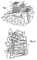
- Figure 1 is a perspective view illustrating the rear and one side of a skid steer loader in accordance with the present invention.
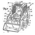
- Figure 2 is a perspective view of the skid steer loader shown in Figure 1, illustrating the front and side.
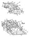
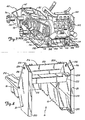
- Figure 3 is a perspective view, taken from the rear, of a lower frame utilized in the skid steer loader shown in Figure 1.
- Figure 4 is a perspective view of a chain case which forms a portion of the lower frame shown in Figure 3.
- Figure 5 is an exploded perspective view of an engine and pump assembly utilized in the vehicle shown in Figure 1.
- Figure 6 is a top view of the engine and pump assembly shown in Figure 5.
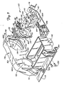
- Figure 7 is a perspective view, taken from the rear, of the lower frame assembly after the engine and pump assembly has been mounted thereon.
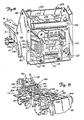
- Figure 8 is a perspective view of the main frame of the loader, taken from the rear side.
- Figure 9 is an exploded view of the main frame shown in Figure 8, with the oil cooler, radiator, hydraulic control valve and fan assembly mounted thereto.
- Figure 10 is a detailed view of the fan shown in Figure 9.
- Figure 11 shows an alternate embodiment of the fan.
- Figure 12 is a perspective view of a partially assembled loader after the main frame has been mounted to the assembly shown in Figure 7.
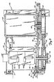
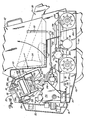
- Figure 13 is a side view of a portion of the loader, with portions cut away.
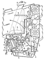
- Figure 14 is a side view of the rear of the loader with portions cut away to illustrate the engine and heat exchanger compartments of the vehicle.
- Figure 15 is a perspective view, taken from the front, of the lower frame assembly after the engine and pump assembly has been mounted thereto.
- Figure 16 is a detailed perspective view, taken from the front, of the engine mount assembly shown in Figure 3.
- Figure 17 is a cross sectional view of the fan shown in Figure 10.
- Figure 18 is a side view of a portion of a second embodiment of the loader, with portions cut away, illustrating a hydraulic motor fan drive mechanism.
- A
skid steer loader 10 in accordance with the present invention is illustrated generally in Figures 1 and 2. As shown,loader 10, includes amain frame assembly 16,lift arm assembly 30 and operator'scompartment 40. Anengine compartment 22 andheat exchanger compartment 24 are located at the rear of the vehicle. A pair ofwheels 12 which are mounted tostub axles 14 extend from both sides ofmain frame 16. - Lift
arm assembly 30 is mounted toupright members 20 ofmain frame assembly 16. As shown,lift arm assembly 30 includes an upper portion formed by a pair oflift arms 32 which overliewheels 12 and are pivotally mounted at a rearward end toupright members 20, and alower portion 33. Pivotally mounted tolower portion 33 is an attachment such asbucket 34. Liftarm assembly 30 is raised and lowered with respect tomain frame assembly 16 by means of a pair ofboom lift cylinders 36, each of which has a first end pivotally mounted to one ofupright members 20, and a second end pivotally mounted to one oflift arms 32.Bucket 34 is rotated with respect to liftarms 32 in a known manner by means of a bucket tilt cylinder (not visible). - Operator's
compartment 40 is partially enclosed by acab 42 which is defined byside guard panels 44,overhead panel 46,rear guard panel 48, backpanel 50 andseat pan 52.Cab 42 is an integral unit which is pivotally mounted at its rear tomain frame 16.Cab 42, includingseat 54 which is mounted to pan 52, can thereby be rotated upwardly and toward the rear ofloader 10 to permit access toengine compartment 22 and other mechanical and hydraulic systems yet to be described. - All functions of
loader 10 can be controlled by an operator from within operator'scompartment 40. The hydraulic drive system described in subsequent portions of this specification is actuated andvehicle 10 steered using a pair oflevers 58, one on each side ofseat 54, which can be moved independently in a forward and rearward direction. Motion oflevers 58causes wheels 12 on that side of the loader to rotate at a speed and in a direction corresponding to the extent and direction in which the respective lever is moved.Boom lift cylinder 36 and the bucket tilt cylinder are actuated by means of foot pedals (Figure 15) mounted toward the front of operator'scompartment 40. The general operation of skid steer loaders such as that illustrated and described above is well known. - The assembly of
loader 10 begins with the fabrication of alower frame assembly 60 which is illustrated generally in Figure 3.Lower frame assembly 60 is fabricated around atransmission case 62 which can be of a conventional design, such as that described in the Bauer et al. U.S. Patent 4,060,261. As perhaps best shown in Figure 4,transmission case 62 is constructed from twoelongated sections top wall 64, side walls 66, (only one of which is visible), and bottom wall (not visible).Top wall 64 includes three openings 71 through which access to mechanical systems withintransmission case 62 can be gained. Side walls 66 each include a motor opening 67. A pair ofaxle housings 74 are welded to and extend from each side wall 66 oftransmission case 62. - A back lower
frame end flange 80 encloses one end oftransmission case 62, and a front lowerframe end flange 82 encloses the opposite end.End flanges transmission case 62. In the embodiment shown,end flanges transmission case 62 and are generally parallel toaxle housings 74.Back end flange 80 has a pair of opposite side edges 84 which are vertically oriented and parallel to transmission case side walls 66, abottom edge 88 andtop edge 92. A pair of integral mountingbrackets 96 extend upward from opposite sides oftop edge 92 ofback end flange 80.Front end flange 82 also has a pair of opposite side edges 86,top edge 94 andbottom edge 90. - Referring back to Figure 3,
lower frame assembly 60 is shown to include a pair ofside flanges 100 which are fabricated from metal and have amotor aperture 102 and a pair ofaxle housing apertures 104.Side flanges 100 are mounted tolower frame assembly 60 withaxle housings 74 extending throughapertures 104. Oppositeedges side flanges 100 fit adjacent and are welded toedges end flanges Flanges 100 are preferably welded toaxle housings 74 as well. Bottom panels 101 (only one is visible in Figure 3) extend between and are welded to back endflange bottom edge 88, front end flangebottom edge 90, side flangelower edges 99, and the lower edges of transmission case side walls 66. The bottom oflower frame 60 is thereby enclosed bybottom panels 101. -
Lower frame assembly 60 also includes an engine mount platform orassembly 110 which is mounted toback end flange 80opposite transmission case 62.Engine mount assembly 110 can be fabricated from a single sheet of metal, and is illustrated in greater detail in Figure 16. As shown,engine mount assembly 110 is fabricated to include a centerbelly pan panel 112, side belly pan panels 111, and vertically orientedside flanges 116. A pair of integral mountingflanges 114 extend laterally from a rear ofside flanges 116.Side flanges 116 and mountingflanges 114 have holes therein to facilitate the mounting ofmain frame assembly 16.Engine mount assembly 110 is an integral element oflower frame assembly 60, being mounted totransmission case 62 by welding forward edges ofpanels 111, 112 andflanges 116 toback end flange 80 as shown in Figure 3. Arear mounting bracket 118 is oriented in a laterally extending direction and welded to a rear edge ofpanels 111, 112 andflanges 114, at the rear ofengine mount assembly 110. - The assembly of
lower frame assembly 60 is completed by mounting ahydraulic motor 78, which in some embodiments also includes a gear reduction mechanism, to each side wall 66 adjacent motor openings 67. An axle shaft (not visible) with awheel mount 76 on one end thereof is rotatably fit within eachaxle housing 74.Hydraulic motors 78 are coupled withintransmission case 62 to the axles on the side of the transmission case to which it is mounted by means of a sprocket and chain linkage (not visible) in a well known manner. Cover plates 70 are then secured totop wall 64 oftransmission case 62, covering openings 71. - While
lower frame assembly 60 is being fabricated and assembled in the manner described above, engine andhydraulic pump assembly 140, which is perhaps best shown in Figures 5 and 6, can be simultaneously assembled. Engine andpump assembly 140 includes an engine 142 (only the case of which is shown in section in Figures 5 and 6 for purposes of clarity), ahydraulic pump assembly 144, and an engine/pump mountingbracket 146.Engine 142 can be of any commercially available type suited to the application, and has adrive shaft 148 which extends from itsflywheel end face 150.Hydraulic pump assembly 144 includes a pair ofvariable displacement pumps pump 147, all of which are driven by acommon drive shaft 152. Driveshaft 152 extends fromfront face 154 ofpump assembly 144.Engine 142 and pumpassembly 144 are manufactured and/or subsequently machined in such a manner that their respectiveflywheel end face 150 andfront face 154 are planar, and perpendicular to theirdrive shafts - Engine/
pump mounting bracket 146 has aback face 156, afront face 158, and aguard rim 160 which extends in a generally perpendicular direction from the periphery of the front face. Mountingbracket 146 is manufactured and/or machined after manufacture so that anengine mounting portion 162A and apump mounting portion 162B ofback face 156 are planar and parallel to one another.Engine 142 is secured to mountingbracket 146 bybolts 164, with itsflywheel end face 150 fit adjacentengine mounting portion 162A ofback face 156. Sincesurfaces shaft 148 extends perpendicularly from engineflywheel end face 150, perpendicular alignment betweenshaft 148 and back face 156 of mountingbracket 146 is ensured. Adrive pulley 198 is then mounted to the end ofengine drive shaft 148. - Engine/
pump mounting bracket 146 also includes astarter motor mount 151 fabricated integrally therewith on its periphery nearengine mounting portion 162A. Starter motor 153 (Figure 12) can be fastened directly to mount 151, and coupled toengine drive shaft 148 through a linkage (not shown) in a convention manner. -
Pump assembly 144 is adjustably secured to mountingbracket 146 by means ofadjustable mounting bracket 168.Bracket 168 is fabricated and/or subsequently machined in such a manner as to include a hydraulic pumpassembly mounting face 170 on one side thereof, and a mutually parallelmounting bracket face 172 on the opposite side. A pair of horizontally oriented slots 174 extend throughbracket 168 near its upper edge, and are positioned in such a manner as to be vertically aligned withbores 176 which extend throughportion 162B of engine/pump mountingbracket 146. Adjustable mountingbracket 168 is sized to have a height greater than the height ofaperture 178 in engine/pump mountingbracket 146. Upper and lower portions of mountingbracket face 172 will therefore extend beyondaperture 178 and fit againstportion 162B ofback face 156 of engine/pump mountingbracket 146. -
Hydraulic pump assembly 144 is mounted tobracket 168 by fasteners (not shown), with itsfront face 154 flush withpump mounting face 170.Adjustable bracket 168, in turn, is mounted to engine/pump mountingbracket 146 by means of bolts 180 which extend through slots 174 and bores 176, and are secured by nuts (not shown). Mountingbracket face 172 ofadjustable bracket 168 will be flush withsurface portion 162B of engine/pump mountingbracket 146. Sincepump shaft 152 is oriented perpendicular tofront face 154, andfront face 154, faces 170 and 172 ofadjustable bracket 168, and pump mountingportion 162B ofbracket 146 are all parallel to one another,pump shaft 152 will be parallel toengine shaft 148 whenhydraulic pump assembly 144 andengine 142 are mounted to engine/pump mountingbracket 146 in the manner described. An integral pump and fan drivepulley unit 196 is mounted to the end ofpump shaft 152.Pump pulley 197 of pump and fan drivepulley unit 196 is coupled bydrive belts 194 toengine pulley 198 as shown.Unit 196 also includes afan drive pulley 251. - The position of
hydraulic pump assembly 144 on engine/pump mountingbracket 146 can be adjusted while at the sametime maintaining shafts brackets adjustment rod 186.Bracket 182 is fastened to engine/pump mountingbracket 146 by means of bolts 188 (Figure 6) and extends from the engine/pump mounting bracket towardhydraulic pump assembly 144.Bracket 184 is secured toadjustable bracket 168 by means ofbolt 190. A semicircularly bent end ofrod 186 extends through a bore inbracket 184 and is secured thereto, while a threaded end ofrod 186 extends through a bore inbracket 182. When bolts 180 are loosened,adjustable bracket 168 andhydraulic pump assembly 144 can be moved horizontally toward or away fromengine 142 by turningnuts 192 which are threaded ontorod 186 on opposite sides ofbracket 182. - Additional support between
engine 142 and pumpassembly 144 is provided bybrackets bracket 204 is fastened bybolts 206 to the side ofengine 142 which facespump assembly 144.Bracket 208 includes anelongated slot 209, and is fastened tobracket 204 withslot 209 opening towardpump assembly 144 and oriented parallel to surface 156 of engine/pump mountingbracket 146.Hydraulic pump 144 is then secured tobracket 208 by one ormore bolts 211 which extend throughslot 209. - Following the assembly of engine and
hydraulic pump assembly 140 in the above-described manner, the position ofhydraulic pump assembly 144 on engine/pump mountingbracket 146 can be adjusted to properlytension belts 194.Bolts 180 and 211 are loosened to permit movement ofadjustable bracket 168 and pumpassembly 144 with respect to engine/pump mountingbracket 146 andengine 142.Nuts 192 are then rotated to movepump assembly 144 toward or away fromengine 142 until the proper tension is applied tobelts 194.Pump assembly 144 is then securely fastened with respect toengine 142 by tighteningbolts 180 and 211. In an alternative embodiment, a spring-loaded idler pulley (not shown) which is mounted tobracket 146 applies pressure to drivebelts 194 at a location intermediate pump and fan drivepulley unit 196 andengine pulley 198, thereby properly tensioning the drive belts. - After it has been assembled and trimmed in the manner described above, engine and
hydraulic pump assembly 140 are mounted toengine mount assembly 110 at the rear oflower frame assembly 60, as shown in Figure 7.Engine 142 is fastened to rear mountingbracket 118 ofengine mount assembly 110 by means ofbrackets 200 andbolts pump mounting bracket 146 andbracket 204 are secured to mountingbrackets 96 oflower frame assembly 60 by bolts 211 (Figures 6, 14 and 15). A fuel tank (not shown) can be located betweenbelly pan panels 111, 112 andengine 142. - From the above description it can be seen that engine/pump mounting
bracket 146permits engine 142 and pumpassembly 144 to be assembled with respect to each other before engine and pumpassembly 140 is mounted tolower frame 60. Tension onbelts 194 can be easily adjusted while at the same time maintaining proper alignment ofengine drive shaft 148 and pumpdrive shaft 152. Furthermore, all of these procedures can be performed beforemain frame 16 is mounted tolower frame 60, hindering access to these portions ofloader 10. Maintenanceprocedures involving motor 142,pump assembly 144 andbelts 194 are also facilitated. - After engine and pump
assembly 110 has been mounted tolower frame 60, hydraulic hoses or lines 350 which provide hydraulic fluid fromvariable displacement pump 143 tohydraulic motor 78 on the right side of theloader 10 can be connected. Similarly,hydraulic lines 352 which supply fluid betweenvariable displacement pump 145 andhydraulic motor 78 on the left side ofloader 10 can be added. These assembly procedures are illustrated in Figure 15.Boom control pedal 282 andbucket control pedal 284, as well as theirrespective linkages lower frame 60 at this time. All mechanical systems onlower frame assembly 60, including engine and pumpassembly 140 and those withintransmission case 62, can be fully tested and adjusted at this time without interference frommain frame 16. These procedures increase manufacturing efficiency. -
Main frame assembly 16 is illustrated in greater detail Figure 8.Main frame assembly 16 is fabricated from steel and includes a pair of longitudinally extending and laterally spaced side beams 18 having outwardly directedupper flanges 210 which will overlie wheels 12 (Figures 1 and 2) and serve as protective fenders forloader 10. Side beams 18 are joined at the front by front cross orwall member 212, and at the rear byupright fabrication 214. The bottom side ofmain frame 16 is completely open. -
Upright fabrication 214 includes a pair ofupright members 20. Eachupright member 20 includes a pair of laterally spacedside portions rear portion 220.Inner side portions 218 abut side beams 18, whileside portions 216 are spaced outwardly fromportions 218 to provide a channel therebetween. Eachside portion 218 has an exhaust port 254 (Figures 1, 2 and 9) located near its forward edge. Mounting brackets 221 (only one is visible in Figure 8) extend between lower edges ofside portions 216 and side beams 18.Front cross member 220 extends betweenside portions 218 near the upper part of the front side ofuprights 20. A generally vertically orientedrear cross member 222 and a generally horizontally orientedtop cross member 224 extend betweenside portions 218 near the upper part of the rear ofuprights 20. Boom pivot mounts 226 to whichboom arms 32 oflift arm assembly 30 are pivotally connected are provided at the upper end of each upright 20. Cab pivot mounts 228 are located on the front side offront cross member 220.Main frame assembly 16 can be similar to that disclosed in the Bauer et al. U.S. Patent 4,055,262, and is preferably fabricated from plates of steel which are welded together. - As shown in Figure 9, a
fan assembly 230,radiator 232,oil cooler 234,muffler 236 andhydraulic control valve 231 can be mounted (by means of fasteners not shown) tomain frame assembly 16 after its fabrication and prior to its positioning onlower frame 60. Hydraulicfluid hoses 233 which couple controlvalve 231 to boomlift cylinders 36,pump assembly 144, the bucket tilt cylinder, and other auxiliary attachments (not shown) can also be easily positioned and secured tomain frame 16 at this time.Radiator 232 andoil cooler 234 are mounted adjacent one another betweenfront cross member 220 andrear cross member 222. This relationship, withradiator 232 positioned belowoil cooler 234, can also be seen in Figures 13 and 14. Grill 28 (Figures 13 and 14), which includes a debris filtering screen (not separately shown), is mounted betweenuprights 20 andcross members oil cooler 234.Muffler 236 is mounted belowtop cross member 224 and to the rear ofrear cross member 222.Exhaust pipe 238 extends frommuffler 236 through an aperture intop cross member 224. -
Fan assembly 230 includes afan shroud 240,radial fan 242, andfan drive 244.Fan shroud 240 can be manufactured from plastic material, and includes acentral portion 246 with a first or upperair intake aperture 248 in the top side thereof. A second or lower air intake aperture 241 (Figures 13 and 14) is located on the bottom side offan shroud 240,opposite aperture 248. A pair ofduct sections 250 communicate with and extend from opposite sides ofcentral portion 246 ofshroud 240. Eachduct section 250 terminates in anexhaust port 252. As perhaps best shown in Figures 13 and 14,fan assembly 230 is mounted immediately belowfront cross member 220 andrear cross member 222. Fanshroud exhaust ports 252 communicate withexhaust ports 254 which open throughmembers 218 ofuprights 20. -
Radial fan 242 is mounted for rotation withincentral portion 246 offan shroud 240, adjacent to and betweenair intake apertures radial fan 242 is a double-bladed fan, having aconcave base 272 with a first set ofheat exchanger blades 274 extending from a first side thereof, and a second set ofengine compartment blades 275 extending from a second side. As shown in Figure 14,radial fan 242 is mounted withinfan shroud 240 withheat exchanger blades 274 extending toward upperair intake aperture 248, andengine compartment blades 275 extending toward lowerair intake aperture 241. For reasons described in subsequent portions of this specification,enqine compartment blades 275 are smaller thanheat exchanger blades 274.Blades base 272 to optimize air flow requirements with power demands.Base 272 is concave so that the center of gravity offan 242 is near the bearings offan drive 244.Radial fan 242 is cast from a magnesium-aluminum alloy in one embodiment. Other materials can be used as well. - Referring again to Figures 9, 13 and 14,
fan drive 244 is a right angle drive mechanism in the illustrated embodiment, and is mounted belowcentral portion 246 offan shroud 240. In other embodiments hydraulic or electric motor drives can be used. The embodiment shown in Figure 18 includes ahydraulic motor 400 which drivesfan 242.Hydraulic motor 400 is coupled to one of the hydraulic pumps by means ofhydraulic hoses 402. Anoutput driveshaft 245 offan drive 244 is connected to base 272 ofradial fan 242.Fan drive 244 has aninput drive shaft 243 which is coupled to hydraulicpump drive shaft 152 throughpulleys belt 253.Radial fan 242 will thereby be rotated withinfan shround 240 byengine 142. The tension onbelt 253 is adjusted by means ofidler pulley 249. - As illustrated in Figure 12,
main frame 16, to which fan assembly 230 (not visible in Figure 12),oil cooler 234,radiator 232,muffler 236 and other mechanical and hydraulic components have been mounted, can next be dropped onto and fastened tolower frame assembly 60. This step is performed after engine andhydraulic pump assembly 140 has been mounted tolower frame assembly 60. Side beams 18 are fastened toside flanges 100 bybolts 290. Mountingbrackets 221 ofuprights 20 are secured to mountingflanges 114 ofengine mount assembly 110, while more forward portions ofuprights 20 are fastened toside flanges 116. Required interconnections between oil cooler 234,radiator 232,muffler 236, andengine 142 can then be easily and conveniently made. - The assembly of remaining structural elements of
loader 10 can then continue in a known manner. Hydraulicfluid hoses 233, which have already been positioned onmain frame 16, can be connected to pumpassembly 144. Control linkages such aslinkage 286 which couplesfoot control pedal 282 tohydraulic control valve 231 can be added.Front closure panels 283 which extend between side beams 18 belowseat pan 52 are fastened in place.Door 26 is hingedly connected to one ofuprights 20 at the rear of the vehicle.Cab 42 is pivotally connected to pivot mounts 228. Liftarm assembly 30 is pivotally mounted touprights 20 at pivot mounts 226. Instrumentation and controls such aslevers 58 withinoperator compartment 40 are also added, as arelinkages 302 which couple these levers tovariable displacement pumps - It can be seen from Figure 13 that
engine compartment 22 has a rearward portion defined at its rear bydoor 26, at its bottom bypanels 111 and 112 ofengine mount assembly 110, at its sides byportions 218 ofuprights 20, at its front by theback wall 50 ofcab 42, and on its top bycross members fan shroud 240. A forward portion ofengine compartment 22 opens intolower frame assembly 60 belowcab 42. This forward portion ofengine compartment 22 is defined byback panel 50 andseat pan 52 ofcab 42,front closure panels 283, side beams 18 ofmain frame 16, andbottom panels 101 andtransmission case 62 oflower frame assembly 60. -
Heat exchanger compartment 24 is defined on its sides byportions 218 ofuprights 20, at its rear bycross member 222, at its front bycross member 220, at the top bygrill 28, and at its bottom by the top surface offan shroud 240. - When
loader 10 is being driven by an operator,radial fan 242 will be rotated at a high speed withinfan shroud 240.Heat exchanger blades 274 will thereby draw fresh ambient air through the screen ofgrill 28,oil cooler 234 andradiator 232, and intofan shroud 240 through itsupper aperture 248. This air, which will have been heated through the transfer of heat when passing throughoil cooler 234 andradiator 232, is discharged fromloader 10 throughfan shroud ducts 250 andexhaust ports 254. Concurrently,engine compartment blades 275 ofradial fan 242 will draw air and debris from withinengine compartment 22. This air and debris will be mixed with the air drawn throughheat exchanger compartment 24, and jointly discharged throughexhaust ports 254. The mass of air drawn fromengine compartment 22 will be relatively small (e.g. 600 CFM) compared to that drawn through grill 28 (e.g. 3600 CFM) sinceheat exchanger blades 274 are larger and configured to be more efficient thanengine compartment blades 275. - The double inlet fan shroud system of
loader 10 has significant advantages over prior art designs. Heated air and debris from withinengine compartment 22 are evacuated without being passed through oil cooler 234 orradiator 232. Temperatures within operator'scompartment 40 can then be maintained at a comfortable level. The relatively small mass of air drawn fromengine compartment 22, with respect to that being drawn throughheat exchanger compartment 24, also helpscool engine 142. Furthermore, by selecting proper fan speed and size ofblades 275, the minimum air flow required to maintain a stable near ambient condition withinengine compartment 22 can be selected. This minimizes the amount of dirt, dust and other debris carried intoengine compartment 22 resulting in a more serviceable unit. The reduced temperatures withinengine compartment 22 also results in a more favorable environment for heat sensitive components. Usable life of seals and other components can thereby be extended. Fresh and therefore relatively cool ambient air (as opposed to heated air from within the engine compartment) is drawn throughheat exchanger compartment 24. The heat transfer efficiency ofoil cooler 234 andradiator 232 are therefore better than if air from within the engine compartment were used. Since the ambient air drawn intoheat exchanger compartment 24 is taken from the top of the vehicle and relatively high above the ground, it will have relatively little dust and debris which might otherwise clog the radiator and oil cooler. This fan system can also be efficiently manufactured. - Yet other advantages of the disclosed double inlet fan system reside in its flexibility. The use of engine/pump mounting
bracket 146 along with the pulley and drive belt linkage permits different engines having various speed and power outputs to be easily coupled to one of a variety of different pumps having various displacements and speed. Fan size, blade configuration and fan speed can also be selected to minimize horsepower consumption and fan noise while maximizing the volumes of air being transmitted. Air flow through the heat exchanger compartment and from the engine compartment can also be independently selected through the configurations of fan blade sizes and aperture openings. Since a variety of different types of fan drives can be used, and speed ratios can be adjusted using different sized pulleys, fan characteristics can be suitably selected to optimize operating characteristics without being limited by engine, pump or vehicle speed. This high degree of flexibility is very important in that it permits a line of differently sized skid steer loader models to be efficiently produced. - An alternative
radial fan 270 is illustrated in Figure 11.Radial fan 270 includes acircular base 256 with a plurality (five are shown) ofair intake apertures 258 which extend therethrough. Mounted tobase 256 and extending perpendicularly therefrom are a plurality offan blades 260. As shown, allfan blades 260 are mounted at the same angle with respect to radial axes ofbase 256. Aring 262 is fastened to the ends offan blade 260opposite base 256. In one embodiment,fan blades 260 are welded to plate 256 andring 262.Fan 270 can be cast or molded from other materials as well. -
Fan 270 can be mounted tooutput drive shaft 245 offan drive 244 in place ofradial fan 242 previously described. Whenloader 10 is being driven by an operator,radial fan 270 will rotate withinfan shroud 240, and draw fresh ambient air through the screen ofgrill 28,oil cooler 234 andradiator 232, and intofan shroud 240 through itsupper intake aperture 248. This air is then discharged fromloader 10 throughfan shroud ducts 250 andexhaust ports 254 in a manner identical to that previously described. Concurrently, air and debris from withinengine compartment 22 will be drawn throughapertures 258 ofplate 256, mixed with the air drawn throughheat exchanger compartment 24, and jointly discharged throughexhaust ports 254. A mass of air drawn throughengine compartment 22 can be selected by varying the size and quantity ofapertures 258. - Although the present invention has been described with reference to preferred embodiments, workers skilled in the art will recognize that changes may be made in form and detail without departing from the spirit and scope of the invention.
Claims (28)
an operator's compartment;
a heat exchanger and engine enclosure located behind the operator's compartment and having an ambient air intake opening and an exhaust port extending therethrough;
a fan shroud mounted within the heat exchanger and engine enclosure and having an enclosure evacuation air intake opening into the heat exchanger and engine enclosure, a heat exchanger air intake, and an exhaust port communicating with the exhaust port extending through the heat exchanger and engine enclosure;
an engine mounted within the heat exchanger and engine enclosure;
a radiator mounted within the heat exchanger and engine enclosure between the ambient air intake and the heat exchanger air intake of the fan shroud;
a radial fan mounted for rotation within the fan shroud between the enclosure evacuation air intake and the heat exchanger air intake; and
fan drive means coupled between the engine and the radial fan for rotating the fan and thereby causing the fan to induce a heat exchanger airflow from the ambient air intake through the radiator and into the fan shroud through the heat exchanger air intake, to induce an enclosure evacuation airflow from within the heat exchanger and engine enclosure into the fan shroud through the enclosure evacuation air intake, and to mix the heat exchanger airflow and enclosure evacuation airflow for joint discharge from the heat exchanger and engine enclosure through its exhaust port.
the heat exchanger and engine enclosure includes:
an engine compartment in which the engine is mounted; and
a heat exchanger compartment, including the ambient air intake, in which the radiator is mounted; and
the fan shroud is mounted with respect to the heat exchanger compartment and the engine compartment with the heat exchanger air intake opening into the heat exchanger compartment and the enclosure evacuation air intake opening into the engine compartment.
the heat exchanger compartment includes top, bottom, front, back and side surfaces, and the ambient air intake extends through the top surface; and
the engine compartment includes top, bottom, front, back and side surfaces.
a base having first and second opposite sides, the first side oriented toward the heat exchanger air intake of the fan shroud, and the second side oriented toward the enclosure evacuation air intake;
a plurality of heat exchanger airflow fan blades extending from the first side of the base; and
a plurality of enclosure evacuation airflow fan blades extending from the second side of the base.
a base having a first side oriented toward the heat exchanger air intake of the fan shroud, and a plurality of apertures therethrough; and
a plurality of fan blades extending from the first side of the base.
the loader further includes a hydraulic pump; and
the fan drive means includes a hydraulic motor coupled to the hydraulic pump, the radial fan being mounted to the hydraulic motor.
an operator's compartment;
an engine compartment located behind the operator's compartment;
a heat exchanger compartment located above at least a portion of the engine compartment and having an ambient air intake extending therethrough;
an engine mounted within the engine compartment;
a radiator mounted within the heat exchanger compartment;
a fan shroud mounted between the heat exchanger compartment and the engine compartment and having a first air intake aperture opening into the heat exchanger compartment, a second air intake aperture opening into the engine compartment, and a first exhaust port;
fan means mounted for rotation within the fan shroud between the first and second air intake apertures for drawing air into the fan shroud through the first and second air intake apertures; and
fan drive means coupled between the engine and the fan means for rotating the fan means and thereby causing the fan means to induce a heat exchanger airflow of ambient air from the ambient air intake through the heat exchanger compartment and into the fan shroud through the first air intake aperture, to induce an engine compartment evacuation airflow from within the engine compartment into the fan shroud through the second air intake aperture, and to mix the heat exchanger and engine compartment evacuation airflows for joint discharge from the loader through the first exhaust port of the fan shroud.
the heat exchanger compartment includes top, bottom, front, back and side walls; and
the engine compartment includes top, bottrom, front, back and side walls.
a loader main frame including a pair of laterally spaced, longitudinally extending side members on opposite sides of the engine forming the side walls of the engine compartment;
an engine mount assembly extending between lower edges of the main frame side members and forming at least a portion of the bottom wall of the engine compartment; and
a door extending between a rear of the main frame side members and the engine mount assembly, the door forming the back wall of the engine compartment.
a lower frame to which the main frame is mounted, the lower frame forming a remaining portion of the bottom wall of the engine compartment;
a front closure panel extending between the main frame side members and the lower frame; and
a cab mounted to the main frame and including a back wall panel extending in a generally downward direction between the side members and a seat panel extending from the back wall panel to the front closure panel between the main frame side members, the rear wall panel and seat panel of the cab along with the front closure panel defining the front of the engine compartment.
the main frame further includes front and rear cross members extending between an upper portion of the side members, the front and rear cross members forming the front wall and back wall of the heat exchanger compartment, and the main frame side members forming side walls of the heat exchanger compartment;
the fan shroud is mounted between the main frame side members below the front and rear cross members and forms the bottom wall of the heat exchanger compartment; and
a grill extending between the side members and front and rear cross members of the main frame, the grill forming a top of the heat exchanger compartment and the ambient air intake.
a base mounted to the fan drive means and having a first side facing the first air intake aperture and a second side facing the second air intake aperture;
a plurality of heat exchanger airflow fan blades extending from the first side of the base; and
a plurality of engine compartment excavation airflow fan blades extending from the second side of the base.
a base mounted to the fan drive means and having a first side facing the first air intake aperture of the fan shroud, and a plurality of apertures therethrough; and
a plurality of fan blades extending from the first side of the base.
the loader further includes a hydraulic pump; and
the fan drive means includes a hydraulic motor coupled to the hydraulic pump, the fan means being mounted to the hydraulic motor.
an engine compartment;
a heat exchanger compartment;
an engine mounted within the engine compartment;
a radiator mounted within the heat exchanger compartment;
a fan shroud having a first intake aperture communicating with the heat exchanger compartment, a second intake aperture communicating with the engine compartment, and an exhaust port;
a radial fan rotatably mounted within the fan shroud between the first and second intake apertures, the radial fan having a base with a first side oriented toward the first intake aperture and a plurality of apertures therethrough, and a plurality of fan blades extending from the first side; and
fan drive means coupling the engine to the radial fan for rotating the fan and causing the fan to induce a heat exchanger airflow through the heat exchanger compartment into the fan shroud through the first intake aperture, to induce an engine compartment evacuation airflow from the engine compartment into the fan shroud through the second intake aperture and apertures of the fan base, and to mix the heat exchanger and engine compartment evacuation airflows for joint discharge through the exhaust port.
Applications Claiming Priority (2)
| Application Number | Priority Date | Filing Date | Title |
|---|---|---|---|
| US07/087,900 US4815550A (en) | 1987-08-21 | 1987-08-21 | Engine cooling system for skid steer loaders |
| US87900 | 1987-08-21 |
Publications (3)
| Publication Number | Publication Date |
|---|---|
| EP0304080A2 true EP0304080A2 (en) | 1989-02-22 |
| EP0304080A3 EP0304080A3 (en) | 1989-12-13 |
| EP0304080B1 EP0304080B1 (en) | 1995-05-10 |
Family
ID=22207929
Family Applications (1)
| Application Number | Title | Priority Date | Filing Date |
|---|---|---|---|
| EP88113508A Expired - Lifetime EP0304080B1 (en) | 1987-08-21 | 1988-08-19 | Off-road vehicle |
Country Status (8)
| Country | Link |
|---|---|
| US (1) | US4815550A (en) |
| EP (1) | EP0304080B1 (en) |
| JP (1) | JP2763110B2 (en) |
| KR (1) | KR960009500B1 (en) |
| AU (1) | AU600850B2 (en) |
| CA (1) | CA1285495C (en) |
| DE (1) | DE3853752T2 (en) |
| WO (1) | WO1989001420A1 (en) |
Cited By (5)
| Publication number | Priority date | Publication date | Assignee | Title |
|---|---|---|---|---|
| DE19532855A1 (en) * | 1995-09-06 | 1997-03-13 | Abb Patent Gmbh | Rail locomotive |
| USH1841H (en) * | 1999-09-09 | 2000-03-07 | Caterpillar Inc. | Air cooled engine enclosure system and apparatus |
| EP1387053A1 (en) * | 2002-08-01 | 2004-02-04 | ebm Werke GmbH & Co. KG | Fan arrangement for cooling of motor vehicle engines |
| US7040837B2 (en) * | 2003-10-10 | 2006-05-09 | Wirtgen Gmbh | Self-propelled road milling machine with cooling system |
| WO2012061450A1 (en) * | 2010-11-03 | 2012-05-10 | Caterpillar Inc. | Skid steer machine having pivotably mounted cooling system and non-metallic vibration isolator |
Families Citing this family (65)
| Publication number | Priority date | Publication date | Assignee | Title |
|---|---|---|---|---|
| US4771844A (en) * | 1987-02-11 | 1988-09-20 | The Toro Company | Method and apparatus for cooling a prime mover |
| US4962825A (en) * | 1987-08-21 | 1990-10-16 | Clark Equipment Company | Skid steer loader |
| US4955455A (en) * | 1987-08-21 | 1990-09-11 | Clark Equipment Company | Method for assembling a skid steer loader |
| US5042602A (en) * | 1989-08-18 | 1991-08-27 | Toyo Umpanki Co., Ltd. | Loader |
| US5251713A (en) * | 1989-09-20 | 1993-10-12 | Honda Giken Kogyo Kabushiki Kaisha | Four wheel vehicle |
| JPH0514776U (en) * | 1991-08-09 | 1993-02-26 | パロマ工業株式会社 | Hot water pipe mounting device |
| JP3053059B2 (en) * | 1994-11-30 | 2000-06-19 | 株式会社クボタ | Work vehicle |
| USD406594S (en) * | 1997-10-17 | 1999-03-09 | Deere & Company | Engine enclosure |
| DE29805539U1 (en) * | 1998-03-26 | 1998-06-18 | Vibromax Bodenverdichtungsmaschinen GmbH, 06466 Gatersleben | Soil compaction machine |
| US6108907A (en) * | 1998-06-05 | 2000-08-29 | Caterpillar S.A.R.L. | Method of assembling a work machine |
| US6092616A (en) * | 1998-06-05 | 2000-07-25 | Caterpillar S.A.R.L. | Cooling system for a skid steer loader |
| US6098739A (en) * | 1998-06-05 | 2000-08-08 | Caterpillar S.A.R.L. | Main frame assembly |
| US6308795B2 (en) * | 1998-12-03 | 2001-10-30 | Caterpillar Inc. | Radiator mounting arrangement for a work machine |
| US6216778B1 (en) | 1998-12-30 | 2001-04-17 | Case Corporation | Cooling system for an off-highway vehicle |
| US6202777B1 (en) | 1999-05-21 | 2001-03-20 | Deere & Company | Engine enclosure with cooling air baffle |
| US6257359B1 (en) | 1999-06-28 | 2001-07-10 | Clark Equipment Company | Air handling system for engines |
| US6223807B1 (en) | 1999-07-09 | 2001-05-01 | Clark Equipment Company | Heating, ventilating and air conditioning system for a skid steer loader |
| US6435144B1 (en) | 1999-11-02 | 2002-08-20 | Caterpillar Inc. | Fan control system and method for simultaneous heat transfer application and engine enclosure ventilation |
| US6431299B1 (en) | 2000-04-05 | 2002-08-13 | Clark Equipment Company | Cooling air ducting for excavator |
| US6871697B2 (en) * | 2002-01-18 | 2005-03-29 | Clark Equipment Company | Integrated fluid reservoir and heat exchanger ducts |
| US6910731B2 (en) | 2002-12-19 | 2005-06-28 | Clark Equipment Company | Skid steer loader with front pivoting cab having a no tool latch |
| US7147076B2 (en) * | 2003-04-02 | 2006-12-12 | Yamaha Hatsudoki Kabushiki Kaisha | Drive system for off-road vehicle |
| US7650959B2 (en) * | 2003-04-02 | 2010-01-26 | Yamaha Hatsudoki Kabushiki Kaisha | Frame arrangement for off-road vehicle |
| US7357211B2 (en) * | 2003-04-02 | 2008-04-15 | Yamaha Hatsudoki Kabushiki Kaisha | Steering system for off-road vehicle |
| US7438147B2 (en) * | 2003-04-02 | 2008-10-21 | Yamaha Hatsudoki Kabushiki Kaisha | Transmission for off-road vehicle |
| US7367417B2 (en) * | 2003-04-02 | 2008-05-06 | Yamaha Hatsudoki Kabushiki Kaisha | Floor arrangement for off-road vehicle |
| US7506712B2 (en) * | 2003-04-02 | 2009-03-24 | Yamaha Hatsudoki Kabushiki Kaisha | Off road vehicle with air intake system |
| US7510199B2 (en) | 2003-04-02 | 2009-03-31 | Yamaha Hatsudoki Kabushiki Kaisha | Off-road vehicle with wheel suspension |
| US7287619B2 (en) * | 2003-04-02 | 2007-10-30 | Yamaha Hatsudoki Kabushiki Kaisha | Air intake system for off-road vehicle |
| US7255189B2 (en) * | 2004-06-18 | 2007-08-14 | Cnh America Llc | Radiator mounting system |
| US7014007B2 (en) * | 2004-06-30 | 2006-03-21 | Mitsubishi Heavy Industries, Ltd. | Body structure of forklift truck |
| US7028646B1 (en) | 2004-12-21 | 2006-04-18 | Cnh America Llp | Cooling system for skid steer loader including fan assembly mounted to engine |
| US7426909B2 (en) * | 2005-12-22 | 2008-09-23 | Caterpillar S.A.R.L. | Cooling system for a machine |
| US7658235B2 (en) * | 2006-08-08 | 2010-02-09 | Clark Equipment Company | Three-point hitch for utility vehicle |
| JP4594942B2 (en) * | 2007-01-16 | 2010-12-08 | コベルコ建機株式会社 | Construction machine cooling structure |
| US7836967B2 (en) | 2008-07-28 | 2010-11-23 | Caterpillar Inc | Cooling system packaging arrangement for a machine |
| JP4831845B2 (en) * | 2008-08-19 | 2011-12-07 | 三菱重工業株式会社 | Battery cooling structure for hybrid industrial vehicles |
| US8016065B2 (en) * | 2008-09-11 | 2011-09-13 | Clark Equipment Company | Split chaincase with fixed axles |
| US8104559B2 (en) * | 2008-09-22 | 2012-01-31 | Clark Equipment Company | Multiple air flow paths using single axial fan |
| US7815000B2 (en) * | 2008-10-15 | 2010-10-19 | Clark Equipment Company | Fully welded track undercarriage transmission with inboard motor mounting flange |
| US8556014B2 (en) * | 2010-11-03 | 2013-10-15 | Caterpillar Inc. | Diesel particulate filter packaging and method of directing airflow in a skid steer machine |
| US8869516B2 (en) * | 2010-11-03 | 2014-10-28 | Caterpillar Sarl | Method of mixing exhaust gas exiting an exhaust stack outlet with cooling air exiting a cooling package outlet and machine using same |
| JP2012106836A (en) * | 2010-11-17 | 2012-06-07 | Tcm Corp | Diesel particulate filter mounting structure for industrial vehicle |
| US8561740B2 (en) * | 2011-02-11 | 2013-10-22 | Cnh America Llc | HVAC system for a work vehicle |
| US8770329B2 (en) * | 2011-07-18 | 2014-07-08 | Caterpillar Forest Products Inc. | Engine cooling system |
| US8418790B2 (en) | 2011-09-20 | 2013-04-16 | Deere & Company | Cooling package baffle or ducting |
| US9873601B2 (en) * | 2013-11-06 | 2018-01-23 | Clark Material Handling Company | Hybrid forklift truck |
| JP5867487B2 (en) | 2013-11-20 | 2016-02-24 | コベルコ建機株式会社 | Construction machinery |
| JP6286338B2 (en) * | 2014-09-30 | 2018-02-28 | 株式会社クボタ | Working machine |
| US9752302B2 (en) | 2014-09-30 | 2017-09-05 | Kubota Corporation | Working machine |
| JP6383234B2 (en) * | 2014-09-30 | 2018-08-29 | 株式会社クボタ | Working machine |
| US9840143B1 (en) | 2015-05-20 | 2017-12-12 | Hydro-Gear Limited Partnership | Cooling pump assembly and cooling system for utility vehicle |
| US10358040B1 (en) | 2015-06-01 | 2019-07-23 | Hydro-Gear Limited Partnership | Drive assembly and system for utility vehicle |
| US10106027B1 (en) | 2015-06-01 | 2018-10-23 | Hydro-Gear Limited Partnership | Generator/cooling assembly and system for utility vehicle |
| US10391854B1 (en) | 2015-06-15 | 2019-08-27 | Hydro-Gear Limited Partnership | Drive and cooling system for utility vehicle |
| US9586466B2 (en) * | 2015-06-23 | 2017-03-07 | Deere & Company | Engine cradle assembly |
| US10093169B1 (en) | 2015-07-09 | 2018-10-09 | Hydro-Gear Limited Partnership | Power and cooling system for utility vehicle |
| JP6617018B2 (en) * | 2015-12-21 | 2019-12-04 | 株式会社神戸製鋼所 | Work machine |
| JP6660173B2 (en) * | 2015-12-21 | 2020-03-11 | 株式会社神戸製鋼所 | Work machine |
| JP6524312B2 (en) * | 2018-05-31 | 2019-06-05 | 株式会社クボタ | Work machine |
| DE102018116452A1 (en) * | 2018-07-06 | 2020-01-09 | Volkswagen Aktiengesellschaft | Mounting arrangement for a heat exchanger |
| US10683640B2 (en) * | 2018-09-21 | 2020-06-16 | Great Plains Manufacturing, Inc. | Hydraulic oil cooling system |
| JP7068205B2 (en) * | 2019-01-15 | 2022-05-16 | トヨタ自動車株式会社 | Engine cooling device |
| CN112452952B (en) * | 2020-11-06 | 2021-10-22 | 山东创瑞激光科技有限公司 | Laser cleaning and cooling device capable of effectively controlling temperature |
| US20220178105A1 (en) * | 2020-12-03 | 2022-06-09 | Deere & Company | Work machine having a radial and vertical lift path with an interchangeable boom assembly pivot |
Citations (8)
| Publication number | Priority date | Publication date | Assignee | Title |
|---|---|---|---|---|
| FR658085A (en) * | 1927-08-10 | 1929-05-30 | Device for preventing dust from entering the hood of an automobile and for cooling the engine | |
| US3642062A (en) * | 1970-08-12 | 1972-02-15 | Daimler Benz Ag | Cooling installation for liquid colled internal combustion engine for driving in particular combat-type vehicles |
| US4117902A (en) * | 1977-02-07 | 1978-10-03 | Clark Equipment Company | Engine cooling system for a skid-steer loader |
| GB2045183A (en) * | 1979-03-13 | 1980-10-29 | Aveling Barford Ltd | Silencing and cooling vehicle engines |
| US4382481A (en) * | 1981-02-02 | 1983-05-10 | Dresser Industries, Inc. | Dual fan engine cooling system |
| JPS58101824A (en) * | 1981-12-10 | 1983-06-17 | Nissan Motor Co Ltd | Radiator cooler of industrial vehicle |
| FR2561709A1 (en) * | 1984-03-23 | 1985-09-27 | Owatonna Mfg Co | Cooling system for utility vehicle |
| EP0182145A1 (en) * | 1984-11-09 | 1986-05-28 | Siemens Aktiengesellschaft | One piece synthetic material fan impeller |
Family Cites Families (26)
| Publication number | Priority date | Publication date | Assignee | Title |
|---|---|---|---|---|
| US737737A (en) * | 1902-01-02 | 1903-09-01 | Eagle Engine Co | Cooling means for gas-engines. |
| US1270124A (en) * | 1917-01-23 | 1918-06-18 | W H Kendricks | Internal-combustion engine. |
| US2175533A (en) * | 1935-09-16 | 1939-10-10 | Ledwinka Hans | Air-cooled internal combustion engine |
| US2317849A (en) * | 1941-01-30 | 1943-04-27 | Baldwin Locomotive Works | Locomotive |
| US2525375A (en) * | 1944-01-25 | 1950-10-10 | Tatra Np | Arrangement of the fuel pump cooling in air-cooled v-type internalcombustion engines |
| US2573544A (en) * | 1946-10-02 | 1951-10-30 | Joseph M Colby | Air-cooled internal-combustion engine |
| US2662748A (en) * | 1952-07-01 | 1953-12-15 | Swingfire Bahamas Ltd | Heat exchanger with adjustable casing for varying recirculation |
| DE1214936B (en) * | 1956-12-07 | 1966-04-21 | Firth Cleveland Ltd | Cooling device for vehicle internal combustion engines |
| US3164140A (en) * | 1963-08-02 | 1965-01-05 | Stevens Inst Technology | Cooling heat turbine for engines |
| BE756733A (en) * | 1969-10-30 | 1971-03-01 | Massey Ferguson Ind Ltd | COOLING SYSTEM FOR COMBINE HARVESTS |
| FR2215840A5 (en) * | 1973-01-30 | 1974-08-23 | Alsthom | |
| US3918547A (en) * | 1973-05-02 | 1975-11-11 | Daimler Benz Ag | Bus with water-cooled rear engine |
| US4173995A (en) * | 1975-02-24 | 1979-11-13 | International Harvester Company | Recirculation barrier for a heat transfer system |
| GB1551362A (en) * | 1975-04-28 | 1979-08-30 | Komatsu Mfg Co Ltd | Radiator assembly |
| US3978938A (en) * | 1975-06-05 | 1976-09-07 | International Harvester Company | Combined airflow with front mounted fuel tank |
| AT354863B (en) * | 1975-06-13 | 1980-02-11 | List Hans | MOTOR VEHICLE WITH A SOUND INSULATING CAPSULE FOR THE ENGINE OR. THE ENGINE-GEAR UNIT |
| US4055262A (en) * | 1976-02-02 | 1977-10-25 | Clark Equipment Company | Loader main frame for skid steer loader |
| US4060261A (en) * | 1976-02-02 | 1977-11-29 | Clark Equipment Company | Loader main frame for skid steer loader |
| US4086976A (en) * | 1977-02-02 | 1978-05-02 | International Harvester Company | Isolated clean air chamber and engine compartment in a tractor vehicle |
| DD140105A1 (en) * | 1978-12-27 | 1980-02-13 | Dieter Berth | AIR GUIDE TO THE COOLING SYSTEM AND DRIVE MOTOR OF A SELF-OPERATING AGRICULTURAL MACHINE |
| SE443408B (en) * | 1979-09-28 | 1986-02-24 | Sueddeutsche Kuehler Behr | RADIAL SPLIT FOR HEATING OR AIR CONDITIONING INSTALLATIONS IN VEHICLES |
| JPS56149022U (en) * | 1980-04-08 | 1981-11-09 | ||
| US4377203A (en) * | 1980-05-20 | 1983-03-22 | Kabushiki Kaisha Komatsu Seisakusho | Radiator equipped with a centrifugal fan |
| US4535868A (en) * | 1983-06-08 | 1985-08-20 | Clark Equipment Company | Transverse engine mounting |
| US4696361A (en) * | 1984-03-23 | 1987-09-29 | Owatonna Manufacturing Company | Swing-up radiator and oil cooler assembly |
| JPH101824A (en) * | 1996-06-11 | 1998-01-06 | Kuraray Co Ltd | Conjugate fiber having sustained-release property |
-
1987
- 1987-08-21 US US07/087,900 patent/US4815550A/en not_active Expired - Lifetime
-
1988
- 1988-08-01 JP JP63190747A patent/JP2763110B2/en not_active Expired - Lifetime
- 1988-08-03 CA CA000573728A patent/CA1285495C/en not_active Expired - Lifetime
- 1988-08-11 AU AU20964/88A patent/AU600850B2/en not_active Ceased
- 1988-08-18 WO PCT/US1988/002835 patent/WO1989001420A1/en unknown
- 1988-08-19 EP EP88113508A patent/EP0304080B1/en not_active Expired - Lifetime
- 1988-08-19 DE DE3853752T patent/DE3853752T2/en not_active Expired - Fee Related
-
1989
- 1989-04-18 KR KR89700669A patent/KR960009500B1/en not_active IP Right Cessation
Patent Citations (8)
| Publication number | Priority date | Publication date | Assignee | Title |
|---|---|---|---|---|
| FR658085A (en) * | 1927-08-10 | 1929-05-30 | Device for preventing dust from entering the hood of an automobile and for cooling the engine | |
| US3642062A (en) * | 1970-08-12 | 1972-02-15 | Daimler Benz Ag | Cooling installation for liquid colled internal combustion engine for driving in particular combat-type vehicles |
| US4117902A (en) * | 1977-02-07 | 1978-10-03 | Clark Equipment Company | Engine cooling system for a skid-steer loader |
| GB2045183A (en) * | 1979-03-13 | 1980-10-29 | Aveling Barford Ltd | Silencing and cooling vehicle engines |
| US4382481A (en) * | 1981-02-02 | 1983-05-10 | Dresser Industries, Inc. | Dual fan engine cooling system |
| JPS58101824A (en) * | 1981-12-10 | 1983-06-17 | Nissan Motor Co Ltd | Radiator cooler of industrial vehicle |
| FR2561709A1 (en) * | 1984-03-23 | 1985-09-27 | Owatonna Mfg Co | Cooling system for utility vehicle |
| EP0182145A1 (en) * | 1984-11-09 | 1986-05-28 | Siemens Aktiengesellschaft | One piece synthetic material fan impeller |
Non-Patent Citations (1)
| Title |
|---|
| PATENT ABSTRACTS OF JAPAN, vol. 7, no. 203 (M-241)[1348], 8th September 1983; & JP-A-58 101 824 (NISSAN JIDOSHA K.K.) 17-06-1983 * |
Cited By (5)
| Publication number | Priority date | Publication date | Assignee | Title |
|---|---|---|---|---|
| DE19532855A1 (en) * | 1995-09-06 | 1997-03-13 | Abb Patent Gmbh | Rail locomotive |
| USH1841H (en) * | 1999-09-09 | 2000-03-07 | Caterpillar Inc. | Air cooled engine enclosure system and apparatus |
| EP1387053A1 (en) * | 2002-08-01 | 2004-02-04 | ebm Werke GmbH & Co. KG | Fan arrangement for cooling of motor vehicle engines |
| US7040837B2 (en) * | 2003-10-10 | 2006-05-09 | Wirtgen Gmbh | Self-propelled road milling machine with cooling system |
| WO2012061450A1 (en) * | 2010-11-03 | 2012-05-10 | Caterpillar Inc. | Skid steer machine having pivotably mounted cooling system and non-metallic vibration isolator |
Also Published As
| Publication number | Publication date |
|---|---|
| US4815550A (en) | 1989-03-28 |
| CA1285495C (en) | 1991-07-02 |
| AU600850B2 (en) | 1990-08-23 |
| EP0304080A3 (en) | 1989-12-13 |
| AU2096488A (en) | 1989-02-23 |
| DE3853752D1 (en) | 1995-06-14 |
| JPS6460714A (en) | 1989-03-07 |
| JP2763110B2 (en) | 1998-06-11 |
| WO1989001420A1 (en) | 1989-02-23 |
| KR890701384A (en) | 1989-12-20 |
| EP0304080B1 (en) | 1995-05-10 |
| KR960009500B1 (en) | 1996-07-20 |
| DE3853752T2 (en) | 1995-12-21 |
Similar Documents
| Publication | Publication Date | Title |
|---|---|---|
| US4815550A (en) | Engine cooling system for skid steer loaders | |
| US4962825A (en) | Skid steer loader | |
| US4955455A (en) | Method for assembling a skid steer loader | |
| US6092616A (en) | Cooling system for a skid steer loader | |
| US6435264B1 (en) | Cooling system for working vehicle | |
| US3868992A (en) | Gross flow cooling system | |
| US8403089B2 (en) | Use of fan shroud to ventilate engine compartment | |
| EP0311853B1 (en) | Skid steer loader and method of assembly | |
| JP2001199251A (en) | Motor unit cooling structure for working vehicle | |
| JP3291776B2 (en) | Riding lawn mower | |
| US7028646B1 (en) | Cooling system for skid steer loader including fan assembly mounted to engine | |
| JP3599479B2 (en) | Riding transplanter | |
| JP3377362B2 (en) | Riding transplanter | |
| JP2511364Y2 (en) | Work vehicle | |
| JP2511365Y2 (en) | Work vehicle engine intake system | |
| JP3046271B2 (en) | Arrangement mechanism of engine etc. in traveling work machine | |
| JP2557571B2 (en) | Lone tractor fuel cock mounting structure | |
| JP2571031Y2 (en) | Combine engine equipment | |
| JP2539692B2 (en) | Counterweight of upper swing construction machine | |
| JP3168352B2 (en) | Combine engine equipment | |
| JPH0629U (en) | Combine engine equipment | |
| JP2788181B2 (en) | Air cleaner mounting structure of compaction machine | |
| JPH0724439Y2 (en) | Skid steer work vehicle | |
| KR20230042553A (en) | Traveling vehicle | |
| JP2000045330A (en) | Cooling equipment for construction machinery |
Legal Events
| Date | Code | Title | Description |
|---|---|---|---|
| PUAI | Public reference made under article 153(3) epc to a published international application that has entered the european phase |
Free format text: ORIGINAL CODE: 0009012 |
|
| AK | Designated contracting states |
Kind code of ref document: A2 Designated state(s): BE DE FR GB IT |
|
| PUAL | Search report despatched |
Free format text: ORIGINAL CODE: 0009013 |
|
| AK | Designated contracting states |
Kind code of ref document: A3 Designated state(s): BE DE FR GB IT |
|
| RIN1 | Information on inventor provided before grant (corrected) |
Inventor name: SCHULT, LESLIE H. Inventor name: LYNNES, CARMAN P. Inventor name: LORAAS, ORLAN J. Inventor name: ALBRIGHT, LARRY E. Inventor name: MATHER, JOSEPH M. |
|
| 17P | Request for examination filed |
Effective date: 19900208 |
|
| 17Q | First examination report despatched |
Effective date: 19910628 |
|
| GRAA | (expected) grant |
Free format text: ORIGINAL CODE: 0009210 |
|
| AK | Designated contracting states |
Kind code of ref document: B1 Designated state(s): BE DE FR GB IT |
|
| ITF | It: translation for a ep patent filed | ||
| REF | Corresponds to: |
Ref document number: 3853752 Country of ref document: DE Date of ref document: 19950614 |
|
| ET | Fr: translation filed | ||
| PLBE | No opposition filed within time limit |
Free format text: ORIGINAL CODE: 0009261 |
|
| STAA | Information on the status of an ep patent application or granted ep patent |
Free format text: STATUS: NO OPPOSITION FILED WITHIN TIME LIMIT |
|
| 26N | No opposition filed | ||
| PGFP | Annual fee paid to national office [announced via postgrant information from national office to epo] |
Ref country code: FR Payment date: 20010801 Year of fee payment: 14 |
|
| PGFP | Annual fee paid to national office [announced via postgrant information from national office to epo] |
Ref country code: DE Payment date: 20010802 Year of fee payment: 14 |
|
| PGFP | Annual fee paid to national office [announced via postgrant information from national office to epo] |
Ref country code: GB Payment date: 20010803 Year of fee payment: 14 |
|
| PGFP | Annual fee paid to national office [announced via postgrant information from national office to epo] |
Ref country code: BE Payment date: 20010903 Year of fee payment: 14 |
|
| REG | Reference to a national code |
Ref country code: GB Ref legal event code: IF02 |
|
| PG25 | Lapsed in a contracting state [announced via postgrant information from national office to epo] |
Ref country code: GB Free format text: LAPSE BECAUSE OF NON-PAYMENT OF DUE FEES Effective date: 20020819 |
|
| PG25 | Lapsed in a contracting state [announced via postgrant information from national office to epo] |
Ref country code: BE Free format text: LAPSE BECAUSE OF NON-PAYMENT OF DUE FEES Effective date: 20020831 |
|
| BERE | Be: lapsed |
Owner name: *CLARK EQUIPMENT CY Effective date: 20020831 |
|
| PG25 | Lapsed in a contracting state [announced via postgrant information from national office to epo] |
Ref country code: DE Free format text: LAPSE BECAUSE OF NON-PAYMENT OF DUE FEES Effective date: 20030301 |
|
| GBPC | Gb: european patent ceased through non-payment of renewal fee |
Effective date: 20020819 |
|
| PG25 | Lapsed in a contracting state [announced via postgrant information from national office to epo] |
Ref country code: FR Free format text: LAPSE BECAUSE OF NON-PAYMENT OF DUE FEES Effective date: 20030430 |
|
| REG | Reference to a national code |
Ref country code: FR Ref legal event code: ST |
|
| PG25 | Lapsed in a contracting state [announced via postgrant information from national office to epo] |
Ref country code: IT Free format text: LAPSE BECAUSE OF NON-PAYMENT OF DUE FEES;WARNING: LAPSES OF ITALIAN PATENTS WITH EFFECTIVE DATE BEFORE 2007 MAY HAVE OCCURRED AT ANY TIME BEFORE 2007. THE CORRECT EFFECTIVE DATE MAY BE DIFFERENT FROM THE ONE RECORDED. Effective date: 20050819 |