EP0303731A1 - Commutator for an electrical machine - Google Patents
Commutator for an electrical machine Download PDFInfo
- Publication number
- EP0303731A1 EP0303731A1 EP87112585A EP87112585A EP0303731A1 EP 0303731 A1 EP0303731 A1 EP 0303731A1 EP 87112585 A EP87112585 A EP 87112585A EP 87112585 A EP87112585 A EP 87112585A EP 0303731 A1 EP0303731 A1 EP 0303731A1
- Authority
- EP
- European Patent Office
- Prior art keywords
- contact material
- commutator
- commutator according
- insert
- groove
- Prior art date
- Legal status (The legal status is an assumption and is not a legal conclusion. Google has not performed a legal analysis and makes no representation as to the accuracy of the status listed.)
- Granted
Links
- OKTJSMMVPCPJKN-UHFFFAOYSA-N Carbon Chemical compound [C] OKTJSMMVPCPJKN-UHFFFAOYSA-N 0.000 claims abstract description 15
- 229910052751 metal Inorganic materials 0.000 claims abstract description 4
- 239000002184 metal Substances 0.000 claims abstract description 4
- 239000000463 material Substances 0.000 claims description 33
- 229910000510 noble metal Inorganic materials 0.000 claims description 23
- 241000446313 Lamella Species 0.000 claims description 7
- 238000004519 manufacturing process Methods 0.000 claims description 6
- 239000000853 adhesive Substances 0.000 claims description 2
- 230000001070 adhesive effect Effects 0.000 claims description 2
- 238000010285 flame spraying Methods 0.000 claims description 2
- 238000005476 soldering Methods 0.000 claims description 2
- 238000003466 welding Methods 0.000 claims description 2
- 239000010970 precious metal Substances 0.000 abstract description 13
- 229910002804 graphite Inorganic materials 0.000 abstract description 6
- 239000010439 graphite Substances 0.000 abstract description 6
- RYGMFSIKBFXOCR-UHFFFAOYSA-N Copper Chemical compound [Cu] RYGMFSIKBFXOCR-UHFFFAOYSA-N 0.000 description 5
- 229910052799 carbon Inorganic materials 0.000 description 5
- 229910052802 copper Inorganic materials 0.000 description 5
- 239000010949 copper Substances 0.000 description 5
- BQCADISMDOOEFD-UHFFFAOYSA-N Silver Chemical compound [Ag] BQCADISMDOOEFD-UHFFFAOYSA-N 0.000 description 3
- 230000015572 biosynthetic process Effects 0.000 description 3
- LTMHDMANZUZIPE-PUGKRICDSA-N digoxin Chemical compound C1[C@H](O)[C@H](O)[C@@H](C)O[C@H]1O[C@@H]1[C@@H](C)O[C@@H](O[C@@H]2[C@H](O[C@@H](O[C@@H]3C[C@@H]4[C@]([C@@H]5[C@H]([C@]6(CC[C@@H]([C@@]6(C)[C@H](O)C5)C=5COC(=O)C=5)O)CC4)(C)CC3)C[C@@H]2O)C)C[C@@H]1O LTMHDMANZUZIPE-PUGKRICDSA-N 0.000 description 3
- 229910052709 silver Inorganic materials 0.000 description 3
- 239000004332 silver Substances 0.000 description 3
- 238000004804 winding Methods 0.000 description 3
- 241001311547 Patina Species 0.000 description 2
- LSNNMFCWUKXFEE-UHFFFAOYSA-N Sulfurous acid Chemical compound OS(O)=O LSNNMFCWUKXFEE-UHFFFAOYSA-N 0.000 description 2
- 238000005299 abrasion Methods 0.000 description 2
- 229910045601 alloy Inorganic materials 0.000 description 2
- 239000000956 alloy Substances 0.000 description 2
- 238000011161 development Methods 0.000 description 2
- 230000007613 environmental effect Effects 0.000 description 2
- 238000007514 turning Methods 0.000 description 2
- 229910000881 Cu alloy Inorganic materials 0.000 description 1
- 230000002411 adverse Effects 0.000 description 1
- 239000012080 ambient air Substances 0.000 description 1
- 238000004873 anchoring Methods 0.000 description 1
- 239000011248 coating agent Substances 0.000 description 1
- 238000000576 coating method Methods 0.000 description 1
- 230000001419 dependent effect Effects 0.000 description 1
- 238000005516 engineering process Methods 0.000 description 1
- 238000011156 evaluation Methods 0.000 description 1
- PCHJSUWPFVWCPO-UHFFFAOYSA-N gold Chemical compound [Au] PCHJSUWPFVWCPO-UHFFFAOYSA-N 0.000 description 1
- 229910052737 gold Inorganic materials 0.000 description 1
- 239000010931 gold Substances 0.000 description 1
- 230000001771 impaired effect Effects 0.000 description 1
- 238000003780 insertion Methods 0.000 description 1
- 230000037431 insertion Effects 0.000 description 1
- 238000009413 insulation Methods 0.000 description 1
- 238000003754 machining Methods 0.000 description 1
- 238000005259 measurement Methods 0.000 description 1
- 238000003801 milling Methods 0.000 description 1
- 230000002093 peripheral effect Effects 0.000 description 1
- 238000012545 processing Methods 0.000 description 1
- 230000001681 protective effect Effects 0.000 description 1
Images

Classifications
-
- H—ELECTRICITY
- H02—GENERATION; CONVERSION OR DISTRIBUTION OF ELECTRIC POWER
- H02K—DYNAMO-ELECTRIC MACHINES
- H02K13/00—Structural associations of current collectors with motors or generators, e.g. brush mounting plates or connections to windings; Disposition of current collectors in motors or generators; Arrangements for improving commutation
- H02K13/10—Arrangements of brushes or commutators specially adapted for improving commutation
- H02K13/105—Spark suppressors associated with the commutator
-
- H—ELECTRICITY
- H01—ELECTRIC ELEMENTS
- H01R—ELECTRICALLY-CONDUCTIVE CONNECTIONS; STRUCTURAL ASSOCIATIONS OF A PLURALITY OF MUTUALLY-INSULATED ELECTRICAL CONNECTING ELEMENTS; COUPLING DEVICES; CURRENT COLLECTORS
- H01R39/00—Rotary current collectors, distributors or interrupters
- H01R39/02—Details for dynamo electric machines
- H01R39/04—Commutators
Definitions
- the invention relates to a commutator for an electrical machine with mutually insulated metal lamellae for voltage or current draw or supply by means of brushes, the lamellae being additionally provided with a contact material to improve sliding contact with the brushes.
- Such commutators are known to be used in generators and motors. In measurement, control and regulation technology, they are used, for example, in direct current tachometer dynamos as measured variable converters. Due to the high terminating resistance of the downstream evaluation unit, the current density in the brushes and the thermal load on the commutator are very low. It is in the range of a few milliamps. For this reason, different criteria for the dimensioning of the commutator and carbon brushes apply to DC tachometer dynamos than, for example, to power machines.
- the lamellae are also electroplated with a noble metal, only a very small layer thickness can be achieved, which is of the order of a few micrometers. This precludes subsequent machining of the commutator running surface, which can only be achieved, for example, by turning to achieve high concentricity. Therefore, the galvanization must be carried out as the last step on the fully assembled armature of the tachometer dynamo, which is very complex and costly. There is also a risk that the galvanic precious metal coating is partially or completely removed by mechanical damage or abrasion during operation.
- the invention has for its object to provide a commutator of the type mentioned, the service life is significantly extended even under unfavorable environmental conditions with good electrical properties and simple manufacture.
- the lamellae are each provided with at least one recess within the running surface of the commutator and that a contact material insert which is flush with the lamella surface is fastened in each recess.
- the invention has the advantage that graphite brushes with good conductivity and lubricity can be used without the risk of disruptive oxide and sulfite layer formation on the collector surface, since neither the noble metal nor the graphite is adversely affected by aggressive environmental influences.
- the groove can be produced in a simple manner, for example by turning, milling or sawing.
- the inlays can be made from prefabricated yard goods.
- the contact material insert has a height of approximately 0.5 mm.
- a preferred embodiment of the invention is that the recess is designed as a groove running in the circumferential direction of the commutator.
- the recess is designed as a groove running in the axial direction of the commutator.
- the groove can be produced and the contact material insert can be introduced in a simple manner.
- the choice of a brush is recommended, the contact area of which in the circumferential direction is greater than the distance between two adjacent contact material inserts, so that the brush is in constant engagement with at least one contact material insert when the commutator is rotated. A change between the contact material insert and the remaining lamella material is prevented in this way.
- the recess is designed as an oblique or arrow-shaped groove. This has the advantage that the entire width of the brush comes into contact with the contact material insert when the slats are swept over and that the commutator is nevertheless provided with the contact material inserts as far as possible in the circumferential direction.
- the recess may also be appropriate for the recess to be designed as a radially extending, round opening, preferably as a blind hole.
- a preferred development is that there are two parallel grooves with contact material inserts in the circumferential direction. This results in multiple direct sliding contact between the brushes and the inserts, or in the case of twin brushes each brush is provided with its own insert. To simplify production, the two inserts can also be designed as a (wider) single insert.
- the contact material insert is designed as a noble metal insert.
- the formation of the groove and the insertion and fastening of the insert is particularly simple if the cross section of the groove and the insert is rectangular or square. Commercial precious metal strips or graphite rods can be used to manufacture the inserts. There are also other groove cross sections, e.g. triangular, trapezoidal and the like, possible.
- the groove and the insert can also be expedient for the groove and the insert to have a cross-section in the form of a segment of a circle.
- the inlays are preferably obtained from round wires or rods, which are twisted to the appropriate cross-section after assembly.
- the insert is particularly easy to produce in the groove by means of a conductive adhesive.
- An alternative attachment can be that the insert is held by soldering, welding or flanging.
- the precious metal insert can also be introduced by flame spraying.
- a particularly simple manufacturing process for the commutator according to the invention consists in that contact material is introduced in one piece into the grooves of a plurality of collector lamellae and then separated between the lamellae.
- the commutator consists of a plurality of lamellae 1 made of copper or a copper alloy. They are held by a cylindrical support 7 made of insulating plastic. In the outer peripheral region, the lamellae 1 are electrically insulated from one another by radially extending slots 8.
- the commutator is placed with a hub 9 together with a rotor on a shaft (not shown) and connected to it in a rotationally fixed manner.
- Each of the fins 1 is connected via winding connections 10 with a corresponding number of rotor windings (not shown posed) connected. For reasons of clarity, only a single winding connection 10 of this type is shown schematically.
- a noble metal insert 2 is introduced into the individual lamellae 1, the effective surface of which occupies only part of the entire running surface.
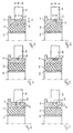
- FIG. 2 shows a cross section along the section line A-A for a first example.
- the same parts as in FIG. 1 are provided with the same reference numerals, as in the figures described below.
- At least one groove 4 extending in the circumferential direction is formed in the lamellae 1, in which the noble metal inserts 2 are inserted and fastened flush with the surface.
- the precious metal inserts 2 lie within the commutator running surface, which is determined by the width of a carbon brush 3.
- the width X of the inserts is expediently smaller than the width B of the commutator running surface; however, it can also be larger.
- the depth T of the groove 4, which corresponds to the height of the noble metal insert 2 is selected so that the commutator can be machined or the like in order to achieve a high concentricity. This ensures that a sufficient amount of the precious metal insert 2 is guaranteed at all times. In practice, a height of the noble metal insert 2 of approximately 0.5 mm has proven itself.
- electrographite is also suitable for the insert in the lamellae 1.
- FIG. 4 shows a triangular and FIG. 5 shows a trapezoidal cross section of the insert 2 and the groove 4.
- FIG. 3 illustrates an example in which the width X of the noble metal insert 2 is significantly smaller than the width B of the tread.
- a dovetail cross section 5 of the noble metal insert 2 is also shown by way of example, with which a particularly firm anchoring in the lamella 1 is achieved.
- FIG. 6 A further variant is shown in FIG. 6, in which two precious metal inserts 2 lying next to one another are incorporated into the lamella 1 within the running surfaces.
- FIG. 7 shows an example of a cross-section in the shape of a segment of a circle of two precious metal inserts 2 arranged next to one another and the associated grooves 4.
- each lamella 1 is provided with a groove 11 which runs in the axial direction of the commutator and which is filled flush with a noble metal insert 2.
- the thickness S of the brush is dimensioned somewhat larger than the distance between the two noble metal inserts 2.
- the noble metal inserts 2 extend over the entire width of the slats 1 extend.
- the noble metal inlays 2 can also be shorter than the width B of the brush 3, corresponding to FIGS. 2 to 5.
- 9 and 10 each show a further arrangement for the noble metal inserts 2 in a top view of a lamella 1.
- 8 illustrates an arrow-shaped groove 12 with the noble metal insert 2.
- the noble metal insert 2 is fastened in a round blind hole 13.
Abstract
Description
Die Erfindung betrifft einen Kommutator für eine elektrische Maschine mit voneinander isolierten Metall-Lamellen zur Spannungs- bzw. Stromabnahme oder Zuführung mittels Bürsten, wobei die Lamellen zur Verbesserung des Gleitkontaktes mit den Bürsten zusätzlich mit einem Kontaktmaterial versehen sind.The invention relates to a commutator for an electrical machine with mutually insulated metal lamellae for voltage or current draw or supply by means of brushes, the lamellae being additionally provided with a contact material to improve sliding contact with the brushes.
Derartige Kommutatoren werden bekanntlich bei Generatoren und Motoren eingesetzt. In der Meß-, Steuer- und Regeltechnik finden sie beispielsweise bei Gleichstrom-Tachometer-Dynamos als Meßgrößen-Umformer Verwendung. Hierbei ist bedingt durch den hohen Abschlußwiderstand der nachgeschalteten Auswerteeinheit die Stromdichte in den Bürsten sowie die thermische Belastung des Kommutators sehr gering. Sie liegt im Bereich von wenigen Milliampere. Deshalb gelten bei Gleichstrom-Tachometer-Dynamos andere Kriterien für die Dimensionierung von Kommutator und Kohlebürsten als beispielsweise bei Leistungsmaschinen.Such commutators are known to be used in generators and motors. In measurement, control and regulation technology, they are used, for example, in direct current tachometer dynamos as measured variable converters. Due to the high terminating resistance of the downstream evaluation unit, the current density in the brushes and the thermal load on the commutator are very low. It is in the range of a few milliamps. For this reason, different criteria for the dimensioning of the commutator and carbon brushes apply to DC tachometer dynamos than, for example, to power machines.
Bei der Kommutierung von Gleichstrom-Tachometer-Dynamos sind einige Varianten bekannt. Wird ein Kupferkommutator zusammen mit Graphitbürsten verwendet, so kann besonders im niedrigen Drehzahlbereich häufig eine hohe Oberwelligkeit des Gleichspannungssignals bei schwankenden Spannungsgradienten beobachtet werden, da sich unvermeidlich Oxid- und Sulfitschichten auf der Oberfläche des Kupferkommutators bilden. In vielen Anwendungsfallen bewähren sich da her silbergraphithaltige Kohlebürsten. Durch den Silberanteil der Kohlebürste bildet sich auf der Lauffläche des Kupferkommutators eine schützende Silbergraphitschicht, die als Patina bezeichnet wird. Diese bewirkt einerseits einen geringen Verschleiß der Kohlebürsten und des Kommutators und andererseits durch ihre hohe elektrische Leitfähigkeit einen guten, gleichmäßigen Kontaktwiderstand. Die Standzeit ist allerdings stark von den Umluftbedingungen abhängig. Bei aggressiver Atmosphäre oder beim Einfluß von Öl oder Fett kommt es zu erhöhtem Abrieb und die Bildung der Patina wird verhindert. Es kann somit wegen der aufgarauhten Oberfläche die Funktionsfähigkeit verstärkt beeinträchtigt werden.Several variants are known for the commutation of direct current tachometer dynamos. If a copper commutator is used together with graphite brushes, a high ripple of the DC voltage signal can often be observed, especially in the low speed range, with fluctuating voltage gradients, since oxide and sulfite layers inevitably form on the surface of the copper commutator. In many applications, they prove their worth forth carbon graphite brushes containing silver. The silver portion of the carbon brush forms a protective silver graphite layer on the tread of the copper commutator, which is called the patina. On the one hand, this causes low wear of the carbon brushes and the commutator, and on the other hand, due to their high electrical conductivity, a good, uniform contact resistance. The service life is strongly dependent on the ambient air conditions. In an aggressive atmosphere or under the influence of oil or fat, there is increased abrasion and the formation of the patina is prevented. The functionality can be impaired because of the roughened surface.
Es ist auch bekannt, die Lamellen des Kommutators aus einem Edelmetall oder einer Edelmetall-Legierung herzustellen. Hierbei müssen sehr hohe Materialkosten wegen des großen Gewichtsanteils des Edelmetalls in Kauf genommen werden.It is also known to produce the lamellae of the commutator from a noble metal or a noble metal alloy. Here, very high material costs have to be accepted because of the large proportion by weight of the precious metal.
Des weiteren ist auch bekannt, auf die Lamellen eine Edelmetallschicht aufzuwalzen. Nachteilig sind hierbei die hohen Material- und Herstellungskosten des Bi-Metalls. Da die Edelmetallschicht die gesamte Oberfläche der Kommutator-Lamellen bedeckt, ist der Edelmetallanteil relativ hoch.Furthermore, it is also known to roll a noble metal layer onto the lamellae. The high material and manufacturing costs of the bimetal are disadvantageous here. Since the noble metal layer covers the entire surface of the commutator lamellae, the proportion of noble metal is relatively high.
Bei seiner ebenfalls angewendeten galvanischen Beschichtung der Lamellen mit einem Edelmetall kann nur eine sehr geringe Schichtdicke erreicht werden, die in der Größenordnung von einigen Mikrometern liegt. Dies schließt eine nachträgliche Bearbeitung der Kommutatorlauffläche aus, die beispielsweise zur Erzielung einer hohen Rundlaufgenauigkeit nur durch Abdrehen erreicht werden kann. Daher muß die Galvanisierung als letzter Arbeitsgang am fertig montierten Anker des Tachometer-Dynamos erfolgen, was sehr aufwendig und kostenträchtig ist. Außerdem besteht die Gefahr, daß die galvanische Edelmetallbeschichtung durch mechanische Beschädigung bzw. Abrieb während des Betriebes teilweise oder vollständig entfernt wird.When the lamellae are also electroplated with a noble metal, only a very small layer thickness can be achieved, which is of the order of a few micrometers. This precludes subsequent machining of the commutator running surface, which can only be achieved, for example, by turning to achieve high concentricity. Therefore, the galvanization must be carried out as the last step on the fully assembled armature of the tachometer dynamo, which is very complex and costly. There is also a risk that the galvanic precious metal coating is partially or completely removed by mechanical damage or abrasion during operation.
Der Erfindung liegt die Aufgabe zugrunde, einen Kommutator der eingangs genannten Art anzugeben, dessen Standzeit auch unter ungünstigen Umweltbedingungen bei gleichzeitig guten elektrischen Eigenschaften und bei einfacher Herstellung wesentlich verlängert ist.The invention has for its object to provide a commutator of the type mentioned, the service life is significantly extended even under unfavorable environmental conditions with good electrical properties and simple manufacture.
Diese Aufgabe wird dadurch gelöst, daß die Lamellen innerhalb der Lauffläche des Kommutators jeweils mit mindestens einer Ausnehmung versehen sind und daß in jeder Ausnehmung eine mit der Lamellenoberfläche bündige Kontaktmaterial-Einlage befestigt ist.This object is achieved in that the lamellae are each provided with at least one recess within the running surface of the commutator and that a contact material insert which is flush with the lamella surface is fastened in each recess.
Die Erfindung hat den Vorteil, daß gut leit- und gleitfähige Graphitbürsten Verwendung finden können, ohne daß die Gefahr von störenden Oxid- und Sulfitschichtbildungen auf der Kollektoroberfläche besteht, da weder das Edelmetall noch der Graphit von aggressiven Umwelteinflüssen beeinträchtigt wird. Durch die Begrenzung der Nut auf die wirksame Kommutatorlauffläche oder auch nur einen Teil davon sind relativ geringe Edelmetallmengen erforderlich. Trotzdem ist eine nachträgliche Bearbeitung der Edelmetallstücke zur Erzielung einer großen Rundlaufgenauigkeit möglich, da das Edelmetall in der Nut ausreichend tief eingebettet ist. Die Herstellung der Nut kann auf einfache Weise, beispielsweise durch Drehen, Fräsen oder Sägen folgen. Die Einlagen können aus vorgefertigter Meterware hergestellt werden.The invention has the advantage that graphite brushes with good conductivity and lubricity can be used without the risk of disruptive oxide and sulfite layer formation on the collector surface, since neither the noble metal nor the graphite is adversely affected by aggressive environmental influences. By limiting the groove to the effective commutator running surface or only a part thereof, relatively small amounts of precious metal are required. Nevertheless, subsequent processing of the precious metal pieces is possible to achieve high concentricity, since the precious metal is embedded sufficiently deep in the groove. The groove can be produced in a simple manner, for example by turning, milling or sawing. The inlays can be made from prefabricated yard goods.
Es ist besonders vorteilhaft, daß die Kontaktmaterial-Einlage eine Höhe von etwa 0,5 mm hat.It is particularly advantageous that the contact material insert has a height of approximately 0.5 mm.
Eine bevorzugte Ausführungsform der Erfindung besteht darin, daß die Ausnehmung als in Umfangsrichtung des Kommutators verlaufende Nut ausgebildet ist.A preferred embodiment of the invention is that the recess is designed as a groove running in the circumferential direction of the commutator.
Es kann alternativ auch vorteilhaft sein, daß die Ausnehmung als in Achsrichtung des Kommutators verlaufende Nut ausgebildet ist. Insbesondere wenn die Lamellen zunächst als Meterware hergestellt werden, von der die einzelnen Lamellen in der gewünschten Breite abgeschnitten werden, kann das Herstellen der Nut und das Einbringen der Kontaktmaterialeinlage auf einfache Weise erfolgen. Bei dieser Variante ist die Wahl einer Bürste zu empfehlen, deren Kontaktbereich in Umfangsrichtung größer ist als der Abstand zweier benachbarter Kontaktmaterialeinlagen, so daß die Bürste bei einer Drehung des Kommutators ständig zumindest mit einer Kontaktmaterialeinlage in Eingriff ist. Ein Wechsel zwischen der Kontaktmaterialeinlage und dem übrigen Lamellenmaterial wird auf diese Weise verhindert. Eine andere alternative Weiterbildung besteht darin, daß die Ausnehmung als schräg- oder pfeilförmig verlaufende Nut ausgebildet ist. Dies hat den Vorteil, daß die gesamte Breite der Bürste beim Überstreichen der Lamellen in Kontakt mit der Kontaktmaterialeinlage gelangt und daß der Kommutator trotzdem in Umfangsrichtung soweit wie möglich mit den Kontaktmaterialeinlagen versehen ist.Alternatively, it can also be advantageous that the recess is designed as a groove running in the axial direction of the commutator. In particular if the slats are first produced by the meter, from which the individual slats are cut off in the desired width, the groove can be produced and the contact material insert can be introduced in a simple manner. In this variant, the choice of a brush is recommended, the contact area of which in the circumferential direction is greater than the distance between two adjacent contact material inserts, so that the brush is in constant engagement with at least one contact material insert when the commutator is rotated. A change between the contact material insert and the remaining lamella material is prevented in this way. Another alternative development is that the recess is designed as an oblique or arrow-shaped groove. This has the advantage that the entire width of the brush comes into contact with the contact material insert when the slats are swept over and that the commutator is nevertheless provided with the contact material inserts as far as possible in the circumferential direction.
Es kann auch zweckmäßig sein, daß die Ausnehmung als radial verlaufenden, runde Öffnung - bevorzugt als Sackloch - ausgebildet ist.It may also be appropriate for the recess to be designed as a radially extending, round opening, preferably as a blind hole.
Eine bevorzugte Weiterbildung besteht darin, daß in Umfangsrichtung zwei parallele Nuten mit Kontaktmaterialeinlagen vorhanden sind. Hierdurch wird ein mehrfacher unmittelbarer Gleitkontakt zwischen den Bürsten und den Einlagen erreicht, oder aber bei Zwillingsbürsten jeder Bürste eine eigene Einlage zur Verfügung gestellt. Zur Vereinfachung der Herstellung können die beiden Einlagen auch als eine (breitere) einzelne Einlage ausgebildet sein.A preferred development is that there are two parallel grooves with contact material inserts in the circumferential direction. This results in multiple direct sliding contact between the brushes and the inserts, or in the case of twin brushes each brush is provided with its own insert. To simplify production, the two inserts can also be designed as a (wider) single insert.
Besonders gute Ergebnisse erhält man, wenn die Kontaktmaterialeinlage als Edelmetalleinlage ausgebildet ist.Particularly good results are obtained if the contact material insert is designed as a noble metal insert.
Eine Alternative besteht darin, daß eine Elektrographiteinlage in den Nuten befestigt ist.An alternative is that an electrographite insert is fixed in the grooves.
Die Ausbildung der Nut und das Einbringen und Befestigen der Einlage ist besonders einfach, wenn der Querschnitt der Nut und der Einlage rechteckig oder quadratisch ist. Handelsübliche Edelmetallbänder oder Graphitstäbe können hierbei zur Herstellung der Einlagen Verwendung finden. Es sind auch andere Nut-Querschnitte, wie z.B. dreieckig, trapezförmig und ähnliches,möglich.The formation of the groove and the insertion and fastening of the insert is particularly simple if the cross section of the groove and the insert is rectangular or square. Commercial precious metal strips or graphite rods can be used to manufacture the inserts. There are also other groove cross sections, e.g. triangular, trapezoidal and the like, possible.
Eine besonders feste Verbindung liegt dann vor, wenn der Querschnitt der Nut und der Einlage schwalbenschwanzförmig ist.A particularly firm connection exists when the cross section of the groove and the insert is dovetail-shaped.
Alternativ dazu kann es auch zweckmäßig sein, daß die Nut und die Einlage einen kreissegmentförmigen Querschnitt aufweisen. Die Einlagen erhält man hierbei bevorzugt aus Runddrähten oder Rundstäben, die nach der Montage auf den entsprechenden Querschnitt abgedreht werden.As an alternative to this, it can also be expedient for the groove and the insert to have a cross-section in the form of a segment of a circle. The inlays are preferably obtained from round wires or rods, which are twisted to the appropriate cross-section after assembly.
Eine besonders einfach herstellbare Befestigung der Einlage in der Nut erfolgt mittels eines leitfähigen Klebers.The insert is particularly easy to produce in the groove by means of a conductive adhesive.
Eine alternative Befestigung kann darin bestehen, daß die Einlage durch Löten, Schweißen oder Bördeln gehalten ist. Die Einbringung der Edelmetalleinlage kann auch durch Flammspritzen erfolgen.An alternative attachment can be that the insert is held by soldering, welding or flanging. The precious metal insert can also be introduced by flame spraying.
Ein besonders einfaches Herstellungsverfahren für den erfindungsgemäßen Kommutator besteht darin, daß Kontaktmaterial einstückig in die Nuten mehrerer Kollektor-Lamellen eingebracht und anschließend zwischen den Lamellen aufgetrennt wird.A particularly simple manufacturing process for the commutator according to the invention consists in that contact material is introduced in one piece into the grooves of a plurality of collector lamellae and then separated between the lamellae.
Alternativ dazu kann es im Hinblick auf die zwischen den Lamellen befindliche Isolierung zweckdienlich sein, daß paßgenau vorgefertigte Einlagen in die betreffenden Nuten eingebracht werden.Alternatively, with regard to the insulation between the lamellae, it may be expedient for inserts which are prefabricated to fit precisely to be introduced into the grooves in question.
Nachfolgend wird die Erfindung anhand von mehreren, in Figuren dargestellten Ausführungsbeispielen weiter beschrieben.
- Fig. 1 zeigt schematisch in perspektivischer Ansicht einen Kommutator und
- Fig. 2 bis 10 zeigen jeweils ein Beispiel für unterschiedliche Ausführungsformen eines Kommutators.
- Fig. 1 shows schematically a perspective view of a commutator and
- 2 to 10 each show an example of different embodiments of a commutator.
Gemäß Fig. 1 besteht der Kommutator aus einer Vielzahl von Lamellen 1 aus Kupfer oder einer Kupferlegierung. Sie werden von einem zylinderförmigen Träger 7 aus isolierendem Kunststoff gehalten. Im äußeren Umfangsbereich sind die Lamellen 1 gegeneinander durch radial verlaufende Schlitze 8 elektrisch voneinander isoliert. Der Kommutator wird mit einer Nabe 9 zusammen mit einem Läufer auf eine Welle (nicht dargestellt) aufgesetzt und mit diesem drehfest verbunden. Jeder der Lamellen 1 ist über Wicklungsanschlüsse 10 mit einer entsprechenden Zahl von Läuferwicklungen (nicht dar gestellt) verbunden. Aus Gründen der Übersichtlichkeit ist lediglich ein einziger derartiger Wicklungsanschluß 10 schematisch wiedergegeben.1, the commutator consists of a plurality of
In der Lauffläche des Kommutators ist in dem in Fig. 1 dargestellten Beispiel in die einzelnen Lamellen 1 jeweils eine Edelmetalleinlage 2 eingebracht, deren wirksame Oberfläche nur einen Teil der gesamten Lauffläche einnimmt.In the example shown in FIG. 1, in the running surface of the commutator, a
In Fig. 2 ist ein Querschnitt entlang der Schnittlinie A-A für ein erstes Beispiel veranschaulicht. Gleiche Teile wie in Fig. 1 sind hierbei - ebenso wie in den nachfolgend beschriebenen Figuren - mit gleichen Bezugszeichen versehen.2 shows a cross section along the section line A-A for a first example. The same parts as in FIG. 1 are provided with the same reference numerals, as in the figures described below.
Allen Beispielen ist gemeinsam, daß in den Lamellen 1 mindestens eine in Umfangsrichtung verlaufende Nut 4 ausgebildet ist, in welcher die Edelmetalleinlagen 2 oberflächenbündig eingelegt und befestigt sind.All examples have in common that at least one
Die Edelmetalleinlagen 2 liegen innerhalb der Kommutatorlauffläche, welche durch die Breite einer Kohlebürste 3 bestimmt ist. Die Breite X der Einlagen ist zweckmäßigerweise kleiner als die Breite B der Kommutatorlauffläche; sie kann jedoch auch größer sein. Die Tiefe T der Nut 4, die der Höhe der Edelmetalleinlage 2 entspricht, ist so gewählt, daß der Kommutator einer spanenden Bearbeitung oder ähnlichem zur Erzielung einer großen Rundlaufeigenschaft aufgesetzt werden kann. Es ist hierbei sichergestellt, daß jederzeit eine ausreichende Höhe der Edelmetalleinlage 2 gewährleistet ist. In der Praxis bewährt sich eine Höhe der Edelmetalleinlage 2 von etwa 0,5 mm.The
Anstelle eines Edelmetalls, wie Gold, Silber oder einer Legierung ist auch Elektrographit für die Einlage in die Lamellen 1 geeignet.Instead of a precious metal, such as gold, silver or an alloy, electrographite is also suitable for the insert in the
Die Fig. 4 zeigt einen dreieckigen und die Fig. 5 einen trapezförmigen Querschnitt der Einlage 2 und der Nut 4.FIG. 4 shows a triangular and FIG. 5 shows a trapezoidal cross section of the
Fig. 3 veranschaulicht ein Beispiel, bei welchem die Breite X der Edelmetalleinlage 2 deutlich kleiner ist als die Breite B der Lauffläche. Es ist ferner beispielhaft ein schwalbenschwanzförmiger Querschnitt 5 der Edelmetalleinlage 2 gezeigt, mit welchem eine besonders feste Verankerung in der Lamelle 1 erreicht wird.FIG. 3 illustrates an example in which the width X of the
In Fig. 6 ist eine weitere Variante dargestellt, bei welcher innerhalb der Laufflächen zwei nebeneinanderliegende Edelmetalleinlagen 2 in die Lamelle 1 eingearbeitet sind.A further variant is shown in FIG. 6, in which two
Fig. 7 zeigt beispielhaft einen kreissegmentförmigen Querschnitt zweier nebeneinander angeordneter Edelmetalleinlagen 2 und der zugehörigen Nuten 4.7 shows an example of a cross-section in the shape of a segment of a circle of two
In Fig. 2 bis 7 ist jeweils nur eine Bürste 3 dargestellt, obwohl in der Praxis auch zwei oder mehr nebeneinander liegende Bürsten verwendet werden können.2 to 7 only one
Fig. 8 veranschaulicht einen Bogensegmentausschnitt des Kommutators mit zwei benachbarten Lamellen 1. Aus dieser Seitenansicht ist ersichtlich, daß jede Lamelle 1 mit einer in Achsrichtung des Kommutators verlaufenden Nut 11 versehen ist, die flächenbündig mit einer Edelmetalleinlage 2 ausgefüllt ist. Um einen Metallwechsel zwischen den Edelmetalleinlagen 2 und dem Kupfer, in das sie eingebettet sind, zu vermeiden, ist die Stärke S der Bürste etwas grösser bemessen als der Abstand der beiden Edelmetalleinlagen 2.8 illustrates an arc segment section of the commutator with two
Die Fig. 8 zeigt ein Beispiel, in welchem sich die Edelmetalleinlagen 2 über die gesamte Breite der Lamellen 1 erstrecken. Um Material einzusparen, können die Edelmetalleinlagen 2 auch in sinngemäßer Entsprechung zu den Fig 2 bis 5 kürzer sein als die Breite B der Bürste 3.8 shows an example in which the
In Fig. 9 und 10 sind jeweils in einer Aufsicht auf eine Lamelle 1 weitere Anordnungen für die Edelmetalleinlagen 2 gezeigt. Dabei veranschaulicht die Fig. 8 eine pfeilförmige Nut 12 mit der Edelmetalleinlage 2. Gemäß Fig. 9 ist die Edelmetalleinlage 2 in einem runden Sackloch 13 befestigt.9 and 10 each show a further arrangement for the
Claims (19)
dadurch gekennzeichnet,
daß die Lamellen (1) innerhalb der Lauffläche des Kommutators jeweils mit einer Ausnehmung versehen sind und daß in jeder Ausnehmung eine mit der Lamellen-Oberfläche bündige Kontaktmaterialeinlage (2) befestigt ist.1. commutator for an electrical machine with mutually insulated metal lamellae for taking off or supplying voltage and current by means of brushes, the lamellae additionally being understood with a contact material to improve sliding contact with the brushes,
characterized by
that the lamellae (1) are each provided with a recess within the running surface of the commutator and that a contact material insert (2) which is flush with the lamella surface is fastened in each recess.
dadurch gekennzeichnet,
daß die Kontaktmaterialeinlage (2) eine Höhe von etwa 0,5 mm hat.2. commutator according to claim 1,
characterized by
that the contact material insert (2) has a height of about 0.5 mm.
dadurch gekennzeichnet,
daß die Breite (X) der Kontaktmaterialeinlage (2) kleiner als die Breite (B) der Bürsten ist.3. commutator according to claim 1 or 2,
characterized by
that the width (X) of the contact material insert (2) is smaller than the width (B) of the brushes.
dadurch gekennzeichnet,
daß die Kontaktmaterialeinlage (2) als Edelmetalleinlage ausgebildet ist.4. commutator according to one of the preceding claims,
characterized by
that the contact material insert (2) is designed as a noble metal insert.
dadurch gekennzeichnet,
daß die Kontaktmaterialeinlage (2) als Elektrographit-Einlage ausgebildet ist.5. commutator according to one of the preceding claims 1 to 3,
characterized by
that the contact material insert (2) is designed as an electrographite insert.
dadurch gekennzeichnet,
daß die Ausnehmung als in Umfangsrichtung des Kommutators verlaufende Nut (4) ausgebildet ist.6. commutator according to one of the preceding claims,
characterized by
that the recess is designed as a groove (4) extending in the circumferential direction of the commutator.
dadurch gekennzeichnet,
daß in Umfangsrichtung zwei parallele Nuten (4) mit Kontaktmaterialeinlagen (2) vorhanden sind.7. commutator according to claim 6,
characterized by
that two parallel grooves (4) with contact material inserts (2) are provided in the circumferential direction.
dadurch gekennzeichnet,
daß die Ausnehmung als in Achsrichtung des Kommutators verlaufende Nut (11) ausgebildet ist.8. commutator according to one of claims 1 to 5,
characterized by
that the recess is designed as a groove (11) extending in the axial direction of the commutator.
dadurch gekennzeichnet,
daß die Ausnehmung als schräg- oder pfeilförmig verlaufende Nut (12) ausgebildet ist.9. commutator according to one of claims 1 to 5,
characterized by
that the recess is designed as an oblique or arrow-shaped groove (12).
dadurch gekennzeichnet,
daß der Querschnitt der Nut (4,11,12) und der Kontaktmaterialeinlage (2) rechteckig ist.10. commutator according to one of claims 6 to 9,
characterized by
that the cross section of the groove (4, 11, 12) and the contact material insert (2) is rectangular.
dadurch gekennzeichnet,
daß der Querschnitt der Nut (4,11,12) und der Kontaktmaterialeinlage (2) quadratisch, dreieckig oder trapezförmig ist.11. commutator according to one of claims 6 to 9,
characterized by
that the cross section of the groove (4, 11, 12) and the contact material insert (2) is square, triangular or trapezoidal.
dadurch gekennzeichnet,
daß der Querschnitt der Nut (4,11,12) und der Kontaktmaterialeinlage (2) schwalbenschwanzförmig ist.12. commutator according to one of claims 6 to 9,
characterized by
that the cross section of the groove (4,11,12) and the contact material insert (2) is dovetail-shaped.
dadurch gekennzeichnet,
daß die Nut (4,11,12) und die Kontaktmaterialeinlage (2) einen kreissegmentförmigen Querschnitt aufweisen.13. commutator according to one of claims 6 to 9,
characterized by
that the groove (4,11,12) and the contact material insert (2) have a circular segment-shaped cross section.
dadurch gekennzeichnet,
daß die Ausnehmung als radial verlaufende Öffnung ausgebildet ist.14. commutator according to one of claims 1 to 5,
characterized by
that the recess is designed as a radially extending opening.
dadurch gekennzeichnet,
daß die Kontaktmaterialeinlage (2) mittels eines leitfähigen Klebers befestigt ist.15. commutator according to one of the preceding claims,
characterized by
that the contact material insert (2) is attached by means of a conductive adhesive.
dadurch gekennzeichnet,
daß die Kontaktmaterialeinlage (2) durch Löten, Schweißen oder Bördeln gehalten ist.16. commutator according to one of claims 1 to 14,
characterized by
that the contact material insert (2) is held by soldering, welding or flanging.
dadurch gekennzeichnet,
daß die Kontaktmaterialeinlage (2) durch Flammspritzen hergestellt ist.17. commutator according to one of claims 1 to 14,
characterized by
that the contact material insert (2) is made by flame spraying.
dadurch gekennzeichnet,
daß zur Herstellung der Kontaktmaterialeinlage (2) Kontaktmaterial einstückig in die Nuten (4,11,12) mehrerer Kollektor-Lamellen eingebracht wird und daß es anschließend zwischen den Lamellen aufgetrennt wird.18. commutator according to one of the preceding claims,
characterized by
that for the manufacture of the contact material insert (2) contact material in one piece in the grooves (4, 11, 12) several collector slats is introduced and that it is then separated between the slats.
dadurch gekennzeichnet,
daß paßgenau vorgefertigte Kontaktmaterialeinlagen (2) in die betreffenden Nuten (4,11,12) eingebracht werden.19. commutator according to one of claims 1 to 18,
characterized by
that prefabricated contact material inserts (2) are introduced into the relevant grooves (4, 11, 12).
Priority Applications (3)
| Application Number | Priority Date | Filing Date | Title |
|---|---|---|---|
| AT87112585T ATE93099T1 (en) | 1987-08-19 | 1987-08-28 | COMMUTATOR FOR AN ELECTRICAL MACHINE. |
| JP19594788A JPH01126144A (en) | 1987-08-19 | 1988-08-05 | Electric machine commutator |
| DD31895788A DD274307A5 (en) | 1987-08-28 | 1988-08-15 | COMMUTATOR FOR AN ELECTRICAL MACHINE |
Applications Claiming Priority (2)
| Application Number | Priority Date | Filing Date | Title |
|---|---|---|---|
| EP87112050 | 1987-08-19 | ||
| EP87112050 | 1987-08-19 |
Publications (2)
| Publication Number | Publication Date |
|---|---|
| EP0303731A1 true EP0303731A1 (en) | 1989-02-22 |
| EP0303731B1 EP0303731B1 (en) | 1993-08-11 |
Family
ID=8197213
Family Applications (1)
| Application Number | Title | Priority Date | Filing Date |
|---|---|---|---|
| EP87112585A Expired - Lifetime EP0303731B1 (en) | 1987-08-19 | 1987-08-28 | Commutator for an electrical machine |
Country Status (4)
| Country | Link |
|---|---|
| US (1) | US4851728A (en) |
| EP (1) | EP0303731B1 (en) |
| DE (1) | DE3787018D1 (en) |
| ES (1) | ES2044885T3 (en) |
Families Citing this family (7)
| Publication number | Priority date | Publication date | Assignee | Title |
|---|---|---|---|---|
| US5175463A (en) * | 1989-08-07 | 1992-12-29 | Kirkwood Industries | Carbon commutator |
| JP3313509B2 (en) * | 1994-04-25 | 2002-08-12 | 株式会社ミツバ | Commitator |
| DE19910130B4 (en) * | 1999-03-01 | 2008-07-03 | Baumer Hübner GmbH | Drehimpulsgeber |
| DE20108461U1 (en) * | 2001-05-19 | 2002-10-02 | Schunk Kohlenstofftechnik Gmbh | Commutator and how to manufacture one |
| WO2011004924A1 (en) * | 2009-07-09 | 2011-01-13 | Lee Moon Hyun | Silver inlaid product and a production method therefor |
| DE102010064321A1 (en) * | 2010-12-29 | 2012-07-05 | Robert Bosch Gmbh | Commutator and manufacturing process for it and electric machine |
| CN104682632A (en) * | 2013-11-29 | 2015-06-03 | 贵州航天林泉电机有限公司 | Method, structure and device for improving contact reliability of electric brush and reverser of direct current speed measuring power generator |
Citations (2)
| Publication number | Priority date | Publication date | Assignee | Title |
|---|---|---|---|---|
| DE2143708B2 (en) * | 1970-09-18 | 1980-01-03 | N.V. Philips' Gloeilampenfabrieken, Eindhoven (Niederlande) | Commutator for a small electrodynamic machine |
| US4415635A (en) * | 1980-04-09 | 1983-11-15 | The University Of Virginia | Electric brush |
Family Cites Families (9)
| Publication number | Priority date | Publication date | Assignee | Title |
|---|---|---|---|---|
| US520264A (en) * | 1894-05-22 | Carl hoffmann | ||
| US257566A (en) * | 1882-05-09 | Commutator for magneto-electric machines | ||
| US258022A (en) * | 1882-05-16 | Commutator for dynamo-electric machines | ||
| US448040A (en) * | 1891-03-10 | Commutator | ||
| US866262A (en) * | 1907-01-24 | 1907-09-17 | Hall Signal Co | Commutator. |
| US2037457A (en) * | 1932-12-28 | 1936-04-14 | Ford Instr Co Inc | Silver faced slip ring |
| US3911303A (en) * | 1971-08-19 | 1975-10-07 | Ibm | Copper commutator-aluminum winding armature |
| US4399383A (en) * | 1978-01-26 | 1983-08-16 | Mitsuba Electric Mfg. Co., Ltd. | Gasoline resistant commutator |
| US4283841A (en) * | 1978-01-26 | 1981-08-18 | Mitsuba Electric Mfg. Co., Ltd. | Method of manufacturing a commutator |
-
1987
- 1987-08-28 ES ES87112585T patent/ES2044885T3/en not_active Expired - Lifetime
- 1987-08-28 DE DE8787112585T patent/DE3787018D1/en not_active Expired - Lifetime
- 1987-08-28 EP EP87112585A patent/EP0303731B1/en not_active Expired - Lifetime
-
1988
- 1988-08-12 US US07/231,877 patent/US4851728A/en not_active Expired - Fee Related
Patent Citations (2)
| Publication number | Priority date | Publication date | Assignee | Title |
|---|---|---|---|---|
| DE2143708B2 (en) * | 1970-09-18 | 1980-01-03 | N.V. Philips' Gloeilampenfabrieken, Eindhoven (Niederlande) | Commutator for a small electrodynamic machine |
| US4415635A (en) * | 1980-04-09 | 1983-11-15 | The University Of Virginia | Electric brush |
Non-Patent Citations (1)
| Title |
|---|
| PATENT ABSTRACTS OF JAPAN, Band 9, Nr. 143 (E-322)[1866], 18. Juni 1985; & JP - A - 60 26435 (MATSUSHITA) 09.02.1985 * |
Also Published As
| Publication number | Publication date |
|---|---|
| EP0303731B1 (en) | 1993-08-11 |
| DE3787018D1 (en) | 1993-09-16 |
| ES2044885T3 (en) | 1994-01-16 |
| US4851728A (en) | 1989-07-25 |
Similar Documents
| Publication | Publication Date | Title |
|---|---|---|
| EP0777312B1 (en) | Stator with connecting arrangement for electrical motors | |
| DE3744488C2 (en) | ||
| DE2800886A1 (en) | DC MOTOR | |
| DE3023108C2 (en) | Method of manufacturing a commutator | |
| DE2610686C2 (en) | Iron-free rotor for an electric motor | |
| EP0303731A1 (en) | Commutator for an electrical machine | |
| DE3710659A1 (en) | ELECTRONICALLY COMMUTED, COLLECTORLESS DC MOTOR | |
| DE2903029C2 (en) | Commutator and process for its manufacture | |
| DE19602771B4 (en) | Rotor for rotating electrical machine | |
| DE3607867C2 (en) | ||
| DE1788164A1 (en) | COMMUTATOR ELEMENTS FOR DYNAMOELECTRIC MACHINERY, SUCH AS DISC RUNNER OR THE SAME | |
| DE4013561A1 (en) | SMALL ENGINE | |
| EP0358812B1 (en) | Brush holder of the cartridge type for a multilayer brush | |
| DE4141307C2 (en) | Brush guide arrangement for an electrical machine | |
| DD274307A5 (en) | COMMUTATOR FOR AN ELECTRICAL MACHINE | |
| DE3614869A1 (en) | Commutator with suppression means | |
| DE3808464A1 (en) | COMMUTATOR DEVICE | |
| DE3420995C2 (en) | DC commutator machine with axially parallel permanent magnets and disc-shaped rotor | |
| DE2525416C2 (en) | ||
| EP1171942B1 (en) | Method for producing an end shield for a commutator machine and an end shield manufactured by such a method | |
| DE3136471C2 (en) | Rotary switch | |
| DE19614219C2 (en) | DC electric motor | |
| DE2949563A1 (en) | Electric miniature motor with equi-spaced collector lamination - has recesses for retaining mixture of conductive particles with oily paste formed by bores extending towards adjacent laminations | |
| DE102004064289B3 (en) | DC motor | |
| DE2261236A1 (en) | DC SMALL MOTOR |
Legal Events
| Date | Code | Title | Description |
|---|---|---|---|
| PUAI | Public reference made under article 153(3) epc to a published international application that has entered the european phase |
Free format text: ORIGINAL CODE: 0009012 |
|
| 17P | Request for examination filed |
Effective date: 19871113 |
|
| AK | Designated contracting states |
Kind code of ref document: A1 Designated state(s): AT CH DE ES FR GB IT LI NL SE |
|
| 17Q | First examination report despatched |
Effective date: 19900813 |
|
| GRAA | (expected) grant |
Free format text: ORIGINAL CODE: 0009210 |
|
| AK | Designated contracting states |
Kind code of ref document: B1 Designated state(s): AT CH DE ES FR GB IT LI NL SE |
|
| REF | Corresponds to: |
Ref document number: 93099 Country of ref document: AT Date of ref document: 19930815 Kind code of ref document: T |
|
| REF | Corresponds to: |
Ref document number: 3787018 Country of ref document: DE Date of ref document: 19930916 |
|
| GBT | Gb: translation of ep patent filed (gb section 77(6)(a)/1977) |
Effective date: 19930819 |
|
| ITF | It: translation for a ep patent filed |
Owner name: DE DOMINICIS & MAYER S. |
|
| ET | Fr: translation filed | ||
| REG | Reference to a national code |
Ref country code: ES Ref legal event code: FG2A Ref document number: 2044885 Country of ref document: ES Kind code of ref document: T3 |
|
| PLBE | No opposition filed within time limit |
Free format text: ORIGINAL CODE: 0009261 |
|
| STAA | Information on the status of an ep patent application or granted ep patent |
Free format text: STATUS: NO OPPOSITION FILED WITHIN TIME LIMIT |
|
| 26N | No opposition filed | ||
| EAL | Se: european patent in force in sweden |
Ref document number: 87112585.2 |
|
| PGFP | Annual fee paid to national office [announced via postgrant information from national office to epo] |
Ref country code: SE Payment date: 19960822 Year of fee payment: 10 Ref country code: AT Payment date: 19960822 Year of fee payment: 10 |
|
| PGFP | Annual fee paid to national office [announced via postgrant information from national office to epo] |
Ref country code: CH Payment date: 19960823 Year of fee payment: 10 |
|
| PGFP | Annual fee paid to national office [announced via postgrant information from national office to epo] |
Ref country code: NL Payment date: 19960828 Year of fee payment: 10 |
|
| PGFP | Annual fee paid to national office [announced via postgrant information from national office to epo] |
Ref country code: ES Payment date: 19960830 Year of fee payment: 10 |
|
| PG25 | Lapsed in a contracting state [announced via postgrant information from national office to epo] |
Ref country code: AT Free format text: LAPSE BECAUSE OF NON-PAYMENT OF DUE FEES Effective date: 19970828 |
|
| PG25 | Lapsed in a contracting state [announced via postgrant information from national office to epo] |
Ref country code: ES Free format text: LAPSE BECAUSE OF NON-PAYMENT OF DUE FEES Effective date: 19970829 Ref country code: SE Free format text: LAPSE BECAUSE OF NON-PAYMENT OF DUE FEES Effective date: 19970829 |
|
| PG25 | Lapsed in a contracting state [announced via postgrant information from national office to epo] |
Ref country code: CH Free format text: LAPSE BECAUSE OF NON-PAYMENT OF DUE FEES Effective date: 19970831 Ref country code: LI Free format text: LAPSE BECAUSE OF NON-PAYMENT OF DUE FEES Effective date: 19970831 |
|
| PG25 | Lapsed in a contracting state [announced via postgrant information from national office to epo] |
Ref country code: NL Free format text: LAPSE BECAUSE OF NON-PAYMENT OF DUE FEES Effective date: 19980301 |
|
| REG | Reference to a national code |
Ref country code: CH Ref legal event code: PL |
|
| EUG | Se: european patent has lapsed |
Ref document number: 87112585.2 |
|
| NLV4 | Nl: lapsed or anulled due to non-payment of the annual fee |
Effective date: 19980301 |
|
| PGFP | Annual fee paid to national office [announced via postgrant information from national office to epo] |
Ref country code: GB Payment date: 19980810 Year of fee payment: 12 |
|
| PG25 | Lapsed in a contracting state [announced via postgrant information from national office to epo] |
Ref country code: GB Free format text: LAPSE BECAUSE OF NON-PAYMENT OF DUE FEES Effective date: 19990828 |
|
| GBPC | Gb: european patent ceased through non-payment of renewal fee |
Effective date: 19990828 |
|
| REG | Reference to a national code |
Ref country code: ES Ref legal event code: FD2A Effective date: 19980910 |
|
| PG25 | Lapsed in a contracting state [announced via postgrant information from national office to epo] |
Ref country code: IT Free format text: LAPSE BECAUSE OF NON-PAYMENT OF DUE FEES Effective date: 20050828 |
|
| PGFP | Annual fee paid to national office [announced via postgrant information from national office to epo] |
Ref country code: DE Payment date: 20060928 Year of fee payment: 20 |
|
| PGFP | Annual fee paid to national office [announced via postgrant information from national office to epo] |
Ref country code: FR Payment date: 20060831 Year of fee payment: 20 |