EP0303531A2 - Geschwindigkeitswandler - Google Patents
Geschwindigkeitswandler Download PDFInfo
- Publication number
- EP0303531A2 EP0303531A2 EP88402027A EP88402027A EP0303531A2 EP 0303531 A2 EP0303531 A2 EP 0303531A2 EP 88402027 A EP88402027 A EP 88402027A EP 88402027 A EP88402027 A EP 88402027A EP 0303531 A2 EP0303531 A2 EP 0303531A2
- Authority
- EP
- European Patent Office
- Prior art keywords
- wedging
- variable speed
- rotary
- speed drive
- elements
- Prior art date
- Legal status (The legal status is an assumption and is not a legal conclusion. Google has not performed a legal analysis and makes no representation as to the accuracy of the status listed.)
- Withdrawn
Links
Images


Classifications
-
- B—PERFORMING OPERATIONS; TRANSPORTING
- B62—LAND VEHICLES FOR TRAVELLING OTHERWISE THAN ON RAILS
- B62M—RIDER PROPULSION OF WHEELED VEHICLES OR SLEDGES; POWERED PROPULSION OF SLEDGES OR SINGLE-TRACK CYCLES; TRANSMISSIONS SPECIALLY ADAPTED FOR SUCH VEHICLES
- B62M9/00—Transmissions characterised by use of an endless chain, belt, or the like
- B62M9/04—Transmissions characterised by use of an endless chain, belt, or the like of changeable ratio
- B62M9/06—Transmissions characterised by use of an endless chain, belt, or the like of changeable ratio using a single chain, belt, or the like
- B62M9/08—Transmissions characterised by use of an endless chain, belt, or the like of changeable ratio using a single chain, belt, or the like involving eccentrically- mounted or elliptically-shaped driving or driven wheel; with expansible driving or driven wheel
-
- F—MECHANICAL ENGINEERING; LIGHTING; HEATING; WEAPONS; BLASTING
- F16—ENGINEERING ELEMENTS AND UNITS; GENERAL MEASURES FOR PRODUCING AND MAINTAINING EFFECTIVE FUNCTIONING OF MACHINES OR INSTALLATIONS; THERMAL INSULATION IN GENERAL
- F16H—GEARING
- F16H29/00—Gearings for conveying rotary motion with intermittently-driving members, e.g. with freewheel action
- F16H29/12—Gearings for conveying rotary motion with intermittently-driving members, e.g. with freewheel action between rotary driving and driven members
- F16H29/16—Gearings for conveying rotary motion with intermittently-driving members, e.g. with freewheel action between rotary driving and driven members in which the transmission ratio is changed by adjustment of the distance between the axes of the rotary members
- F16H29/18—Gearings for conveying rotary motion with intermittently-driving members, e.g. with freewheel action between rotary driving and driven members in which the transmission ratio is changed by adjustment of the distance between the axes of the rotary members in which the intermittently-driving members slide along approximately radial guides while rotating with one of the rotary members
Definitions
- variable speed drives allowing an infinite number of speed ratios between two different rotary shafts, and this over a more or less wide range.
- Such variable speed drives are susceptible of very numerous applications. Thus they can be used on motor vehicles or on cycles, or even on any mechanical machines or devices.
- variable speed drives of the type comprising two elements -respectively leading and mounted rotatably about two parallel axes, one of which is movable relative to the other, and which are connected one to the other. the other by unidirectional coupling members capable of acting one after the other in turn, which are carried by one of the rotary transmission elements, while being capable of being more or less separated from the axis thereof according to the eccentricity of this axis relative to the other.
- variators of this kind it is thus possible to vary the transmission ratio continuously by modifying the eccentricity of one of the rotary transmission elements relative to the other.
- the document EP 208,473 describes a variable speed drive of this type.
- one of the rotary transmission elements carries a series of articulated arms, the ends of which constitute pawls intended to come into engagement with a ratchet wheel having an internal toothing.
- the modification of the eccentricity of one of the rotary elements relative to the other causes a variation in the angular position of the coupling arms, and consequently a variation in the transmission ratio.
- each of the unidirectional coupling members consists of a stud capable of jamming on a circular track, or in a groove also circular, provided on one of the elements rotary transmission, this stud being mounted articulated on a slider itself mounted sliding in a slot or diametrical groove formed in the other rotary transmission element, the arrangement being such that under the effect of the rotation of the element leading the coupling studs come one after the other, in turn, in the wedging position.
- the engagement of another coupling member with the opposite rotating element takes place at any point of the track or of the circular groove thereof as soon as this jamming occurs.
- the arrangement provided provides fully satisfactory mechanical strength since the coupling is effected by wedging on a relatively large contact surface.
- each of the unidirectional wedging studs is articulated on the corresponding slide by means of a coupling rod.
- the presence of this link compensates for differences in the radii of action and thus minimize the friction occurring in the absence of such a link.
- the rotary transmission element which comprises a circular track or groove for receiving the wedging studs, consists of a ring rotatably mounted around a circular core to which is attached a means of actuation, for example a traction cable, making it possible to cause the eccentricity of this core, and consequently of the rotary crown relative to the axis of the other rotary element of the transmission.
- variable speed drive according to the invention.
- This relates, simply by way of example, to a variator fitted to a bicycle. But again, this dimmer could give rise to any other application.
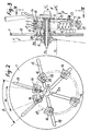
- the variator shown by way of example in FIGS. 1 to 5 is fitted to the rear wheel of a bicycle.
- the rotary elements - driven and driving - of this variator are constituted respectively by a circular plate 1 and a crown 2, on which is fixed the pinion 3 for driving the corresponding rear wheel 4, the drive chain 5 being disposed on this pinion .
- the pinion 3 is fixed on the crown 2 by a series of screws 14 which also ensure that of an external ring 15.
- the rotary plate 1 it is fixed, by screwing or other means, to the hub 6 of the corresponding wheel 4.
- this plate is coupled in rotation with this hub and it rotates around the axis XX ′ of the wheel.
- the crown 2 is rotatably mounted around a core 7 of circular outline, and this with the interposition of an annular bearing 8.
- the axis Y-Y ′ of this core constitutes the axis of rotation of this crown.
- this axis which is parallel to the axis XX ′ of the wheel, is capable of being displaced in translation relative to the latter to cause eccentricity between the two rotary elements 1 and 2 of the variator and to vary will this offset.
- the core 7 is slidably mounted on a guide rod 9 attached at right angles to the axis 10 of the wheel.
- a coil spring 11 is interposed between the end of this rod 9 and the bottom of the housing provided for the latter inside the core 7.
- this spring tends to maintain, or recall, the core 7 in a position for which its axis YY ′ has a maximum spacing E with respect to the axis XX ′ of the wheel.
- a traction cable 12, attached at 13 to the core 7, makes it possible to move the latter in the direction of the arrow F, against the action of the spring 11, to reduce the eccentricity between the two axes.
- XX ′ and YY ′ this cable can be operated remotely by the cyclist in the same way as a derailleur cable.
- the unidirectional coupling members provided between the two rotary transmission elements 1 and 2 consist of wedging studs 16. Each of these studs has the general shape of a U-shaped section jumper whose walls are curved. Each of these riders is placed on horseback on a circular track 17 carried by the face of the crown 2 which is turned towards the plate 1.
- each of these studs is hinged on a slide 18 which is itself slidably mounted in a radial slot 19 formed in the plate 1.
- the articulation of each stud 16 on the corresponding slide is effected by means of an axis 20 whose position on this stud is offset from its median transverse plane ZZ ′.
- This offset is a function of the direction of rotation F1 of the crown 2 and it is such that the rotation of the latter causes, in a certain position, the rearing of the corresponding slide and consequently its jamming on the track 17.
- the internal faces of the two walls of each stud 16 advantageously comprise recessed parts 21a and 21b whose staggered arrangement on either side of the median transverse plane ZZ ′, takes account of the direction of rotation provided.
- any traction exerted on the cable 12 has the effect of modifying the eccentricity between the two rotary elements 1 and 2.
- the core 7 comes into abutment and it occupies a position centered by relative to the axis of the wheel, the two axes XX ′ and YY ′ being in coincidence.
- the wedging pads 16 are all placed on the same circumference. Since they are thus at equal distance from the wheel, no differential speed appears between them. Consequently, the driven plate 1 is driven at the same speed as the crown 2 and the toothed pinion 3 which is integral therewith.
- a loosening of the cable 12 causes the core 7 to return to the eccentric position, and this under the action of the return spring 11.
- This eccentricity causes a continuous variation of the radii on which the wedging pads 16 move relative to the center of the wheel . Due to this eccentricity, the angles traversed by these studs become different.
- a differential speed therefore appears: the angle ⁇ of driving a stud 16 relative to the center of rotation O1 of the driving pinion 3 becomes smaller in the area where the studs 16 are closer to the center 02 of the wheel. At this point, the angle ⁇ traversed by the toothed pinion 3 is smaller than the angle ⁇ traversed by the drive plate 1.
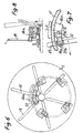
- FIGS. 6 and 7 illustrate an alternative embodiment in which each wedging pin 16a is articulated on the corresponding slide 18a by means of a traction rod 22.
- One of the ends of this rod is articulated by means an axis 20a on the stud considered 16a.
- axis 20b is articulated on the slide 18a by means of an axis 20b. Again the position of the axis 20a on the pad 16a is offset from the median transverse plane Z-Z ′ thereof.
- variable speed drive according to the invention is not limited to the examples described above.
- the wedging studs could be arranged inside a groove on a circular track, the wedging studs could be arranged inside an annular groove, the arrangement being such that each of these studs can get jammed inside this groove to achieve the same effect as above.
- the variator shown in the accompanying drawings is intended to equip the rear wheel of a bicycle.
- the variator according to the invention can be the subject of numerous other applications in the most diverse fields.
- the variator according to the invention has many advantages. The main of them lies in the high mechanical strength ensured by the fact that the coupling between the rotary transmission members is effected by wedging on a relatively large surface. Another advantage results from the fact that such a wedging coupling can occur at any point of the circular track carried by the corresponding rotary transmission element.
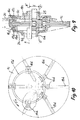
- FIGS 8 and 9 show another embodiment of the variator according to the invention.
- the corresponding device constitutes a variator with a double multiplication stage.
- the first stage of the device in question comprises a circular track 17c secured to the corresponding driving pinion 3c, these two elements being mounted to rotate about an axis XX ′ by means of a bearing 8c.
- the second floor it has another circular track 17d rotatably mounted around the same axis XX ′ by through another bearing 8d. This second track is carried by a disc 24 fixed to the hub 6d of the wheel to be driven.
- each stud 16c in turn drives the plate 1c and then each stud 16d in turn drives the track 17d secured to the hub 6d.
- the two series of studs 16c and 16d should be adapted to wedge for the same direction of rotation of the motor F ′ of the elements of the variator.
- the speed ratio between the driving pinion 3c and the driven hub 6d is varied by varying the distance E between the two axes XX ′ and ZZ ′.
- the movement of the movable axis ZZ ′ of the plate 1c can be controlled by rotation of a crankshaft 25. While using only one plate 1c with radial grooves, the present device thus constitutes a variator with two stages whose driving shaft and driven shaft remain coaxial, whatever the eccentricity of this plate.
Landscapes
- Engineering & Computer Science (AREA)
- General Engineering & Computer Science (AREA)
- Mechanical Engineering (AREA)
- Chemical & Material Sciences (AREA)
- Combustion & Propulsion (AREA)
- Transportation (AREA)
- Friction Gearing (AREA)
Applications Claiming Priority (2)
| Application Number | Priority Date | Filing Date | Title |
|---|---|---|---|
| CH307887 | 1987-08-11 | ||
| CH3078/87 | 1987-08-11 |
Publications (2)
| Publication Number | Publication Date |
|---|---|
| EP0303531A2 true EP0303531A2 (de) | 1989-02-15 |
| EP0303531A3 EP0303531A3 (de) | 1990-06-20 |
Family
ID=4248137
Family Applications (1)
| Application Number | Title | Priority Date | Filing Date |
|---|---|---|---|
| EP88402027A Withdrawn EP0303531A3 (de) | 1987-08-11 | 1988-08-03 | Geschwindigkeitswandler |
Country Status (1)
| Country | Link |
|---|---|
| EP (1) | EP0303531A3 (de) |
Cited By (11)
| Publication number | Priority date | Publication date | Assignee | Title |
|---|---|---|---|---|
| EP0392807A3 (de) * | 1989-04-13 | 1991-01-23 | Maz Wen | Antrieb mit variablem Übersetzungsverhältnis |
| DE4121424A1 (de) * | 1991-06-30 | 1993-01-14 | Werker Joachim | Kurbelantrieb |
| EP0645301A1 (de) * | 1993-09-24 | 1995-03-29 | Harold Armstead Hunter, Jr. | Stufenloses Getriebe |
| WO1997038893A1 (en) * | 1996-04-16 | 1997-10-23 | John James Jago | Chain or belt drive system |
| NL1006744C2 (nl) * | 1997-08-08 | 1999-01-08 | Heerke Hoogenberg | Traploos drijfwerk. |
| WO1999009336A1 (de) * | 1997-08-13 | 1999-02-25 | Satellite Gear Systems Ltd. | Richtungsgeschaltete kupplung |
| WO2004065823A1 (en) * | 2003-01-22 | 2004-08-05 | Karjatse, Paavi | Transmission device |
| CN100406777C (zh) * | 2004-12-27 | 2008-07-30 | 刘海平 | 摆动式滑块无级变速器 |
| CN102562866A (zh) * | 2010-12-24 | 2012-07-11 | 杨苏淑宽 | 具有斜曲面的滑块组件 |
| CN110979545A (zh) * | 2019-12-02 | 2020-04-10 | 叶驰 | 一种自行车的变速装置 |
| WO2022248136A3 (en) * | 2021-05-28 | 2023-01-05 | Classified Cycling Bv | Continuously variable transmission unit, preferably for a bicycle |
Family Cites Families (2)
| Publication number | Priority date | Publication date | Assignee | Title |
|---|---|---|---|---|
| DE691043C (de) * | 1935-08-08 | 1940-05-15 | Friedrich Cavallo | Schaltwerksgetriebe |
| AU6891387A (en) * | 1986-02-10 | 1987-08-25 | Stranieri, M. | Continuous speed gear functioning by means of cog wheels with cogs of variable radius |
-
1988
- 1988-08-03 EP EP88402027A patent/EP0303531A3/de not_active Withdrawn
Cited By (12)
| Publication number | Priority date | Publication date | Assignee | Title |
|---|---|---|---|---|
| EP0392807A3 (de) * | 1989-04-13 | 1991-01-23 | Maz Wen | Antrieb mit variablem Übersetzungsverhältnis |
| DE4121424A1 (de) * | 1991-06-30 | 1993-01-14 | Werker Joachim | Kurbelantrieb |
| EP0645301A1 (de) * | 1993-09-24 | 1995-03-29 | Harold Armstead Hunter, Jr. | Stufenloses Getriebe |
| WO1997038893A1 (en) * | 1996-04-16 | 1997-10-23 | John James Jago | Chain or belt drive system |
| NL1006744C2 (nl) * | 1997-08-08 | 1999-01-08 | Heerke Hoogenberg | Traploos drijfwerk. |
| WO1999009336A1 (de) * | 1997-08-13 | 1999-02-25 | Satellite Gear Systems Ltd. | Richtungsgeschaltete kupplung |
| US6327926B1 (en) | 1997-08-13 | 2001-12-11 | Satellite Gear Systems Ltd. | Directional clutch |
| WO2004065823A1 (en) * | 2003-01-22 | 2004-08-05 | Karjatse, Paavi | Transmission device |
| CN100406777C (zh) * | 2004-12-27 | 2008-07-30 | 刘海平 | 摆动式滑块无级变速器 |
| CN102562866A (zh) * | 2010-12-24 | 2012-07-11 | 杨苏淑宽 | 具有斜曲面的滑块组件 |
| CN110979545A (zh) * | 2019-12-02 | 2020-04-10 | 叶驰 | 一种自行车的变速装置 |
| WO2022248136A3 (en) * | 2021-05-28 | 2023-01-05 | Classified Cycling Bv | Continuously variable transmission unit, preferably for a bicycle |
Also Published As
| Publication number | Publication date |
|---|---|
| EP0303531A3 (de) | 1990-06-20 |
Similar Documents
| Publication | Publication Date | Title |
|---|---|---|
| EP2021647B1 (de) | Wegminderungsaktuator, speziell für eine kraftfahrzeugkupplung | |
| EP3959449B1 (de) | Getriebekasten und motor mit einem solchen getriebekasten | |
| FR2824376A1 (fr) | Transmission de vitesse pour tondeuse a gazon automotrice et tondeuse equipee d'une telle transmission | |
| EP0303531A2 (de) | Geschwindigkeitswandler | |
| EP0081025B1 (de) | Rotationsservomechanismus, insbesondere für eine Fahrzeuglenkung | |
| EP0362016A1 (de) | Geschwindigkeitswandler | |
| FR3008956A1 (fr) | Dispositif d'entrainement en rotation d'une roue d'aeronef | |
| FR2856019A1 (fr) | Garniture d'articulation pour un dispositif de reglage d'un siege de vehicule automobile | |
| FR2494196A1 (fr) | Retroviseur telecommandable pour vehicule automobile | |
| FR2658892A1 (fr) | Poulie menee d'une transmission a vitesse variable. | |
| FR2709798A1 (fr) | Boîte de vitesse à embrayage incorporé. | |
| FR2476256A1 (fr) | Roue de transmission a diametre variable | |
| FR3152299A1 (fr) | Transmission du type à cardan pour véhicule | |
| FR2774953A1 (fr) | Transmission de vitesse pour tondeuse a gazon et tondeuse a gazon equipee d'une telle transmission | |
| FR2528513A1 (fr) | Dispositif de reglage automatique du jeu pour frein a tambour | |
| FR2637250A1 (fr) | Variateur de vitesse pour cycle | |
| FR2640715A1 (en) | Speed varier | |
| FR2720805A1 (fr) | Mécanisme de transmission à plusieurs modes de fonctionnement commandés. | |
| FR2830301A1 (fr) | Dispositif d'entrainement en rotation alternatif de deux arbres menes montes concentriques a partir d'un seul arbre d'entrainement | |
| WO2017207917A1 (fr) | Actionneur pour un embrayage, notamment de vehicule automobile | |
| FR3066470B1 (fr) | Dispositif de regulation de transmission par chaine | |
| FR3149662A1 (fr) | Variateur à organe de transfert de puissance trapézoïdal | |
| FR3059752A1 (fr) | Moyen d'agrippement autobloquant d'un systeme de transmission continument variable | |
| FR3031962A1 (fr) | Procede d'entrainement en rotation d'une roue d'aeronef. | |
| EP2909070A1 (de) | Getriebeanordnung für eine selbstfahrende maschine und mit einem solchen getriebe ausgestattete maschine |
Legal Events
| Date | Code | Title | Description |
|---|---|---|---|
| PUAI | Public reference made under article 153(3) epc to a published international application that has entered the european phase |
Free format text: ORIGINAL CODE: 0009012 |
|
| AK | Designated contracting states |
Kind code of ref document: A2 Designated state(s): BE CH DE ES FR GB IT LI LU NL |
|
| PUAL | Search report despatched |
Free format text: ORIGINAL CODE: 0009013 |
|
| AK | Designated contracting states |
Kind code of ref document: A3 Designated state(s): BE CH DE ES FR GB IT LI LU NL |
|
| 17P | Request for examination filed |
Effective date: 19900806 |
|
| 17Q | First examination report despatched |
Effective date: 19910923 |
|
| STAA | Information on the status of an ep patent application or granted ep patent |
Free format text: STATUS: THE APPLICATION HAS BEEN WITHDRAWN |
|
| 18W | Application withdrawn |
Withdrawal date: 19911227 |