EP0303414B1 - Assemblage montant et lisse - Google Patents
Assemblage montant et lisse Download PDFInfo
- Publication number
- EP0303414B1 EP0303414B1 EP88307272A EP88307272A EP0303414B1 EP 0303414 B1 EP0303414 B1 EP 0303414B1 EP 88307272 A EP88307272 A EP 88307272A EP 88307272 A EP88307272 A EP 88307272A EP 0303414 B1 EP0303414 B1 EP 0303414B1
- Authority
- EP
- European Patent Office
- Prior art keywords
- post
- aperture
- tether
- rail
- rail assembly
- Prior art date
- Legal status (The legal status is an assumption and is not a legal conclusion. Google has not performed a legal analysis and makes no representation as to the accuracy of the status listed.)
- Expired - Lifetime
Links
- 230000004888 barrier function Effects 0.000 description 10
- 238000000034 method Methods 0.000 description 3
- 230000000712 assembly Effects 0.000 description 2
- 238000000429 assembly Methods 0.000 description 2
- 239000000463 material Substances 0.000 description 2
- 229920003023 plastic Polymers 0.000 description 2
- 239000004033 plastic Substances 0.000 description 2
- 239000007787 solid Substances 0.000 description 2
- 235000013290 Sagittaria latifolia Nutrition 0.000 description 1
- 230000001154 acute effect Effects 0.000 description 1
- 235000015246 common arrowhead Nutrition 0.000 description 1
- 230000009977 dual effect Effects 0.000 description 1
- 230000000694 effects Effects 0.000 description 1
- 229920002457 flexible plastic Polymers 0.000 description 1
- 239000007788 liquid Substances 0.000 description 1
- 239000002184 metal Substances 0.000 description 1
Images

Classifications
-
- E—FIXED CONSTRUCTIONS
- E01—CONSTRUCTION OF ROADS, RAILWAYS, OR BRIDGES
- E01F—ADDITIONAL WORK, SUCH AS EQUIPPING ROADS OR THE CONSTRUCTION OF PLATFORMS, HELICOPTER LANDING STAGES, SIGNS, SNOW FENCES, OR THE LIKE
- E01F13/00—Arrangements for obstructing or restricting traffic, e.g. gates, barricades ; Preventing passage of vehicles of selected category or dimensions
- E01F13/02—Arrangements for obstructing or restricting traffic, e.g. gates, barricades ; Preventing passage of vehicles of selected category or dimensions free-standing; portable, e.g. for guarding open manholes ; Portable signs or signals specially adapted for fitting to portable barriers
- E01F13/028—Flexible barrier members, e.g. cords; Means for rendering same conspicuous; Adapted supports, e.g. with storage reel
-
- E—FIXED CONSTRUCTIONS
- E01—CONSTRUCTION OF ROADS, RAILWAYS, OR BRIDGES
- E01F—ADDITIONAL WORK, SUCH AS EQUIPPING ROADS OR THE CONSTRUCTION OF PLATFORMS, HELICOPTER LANDING STAGES, SIGNS, SNOW FENCES, OR THE LIKE
- E01F13/00—Arrangements for obstructing or restricting traffic, e.g. gates, barricades ; Preventing passage of vehicles of selected category or dimensions
- E01F13/02—Arrangements for obstructing or restricting traffic, e.g. gates, barricades ; Preventing passage of vehicles of selected category or dimensions free-standing; portable, e.g. for guarding open manholes ; Portable signs or signals specially adapted for fitting to portable barriers
-
- E—FIXED CONSTRUCTIONS
- E01—CONSTRUCTION OF ROADS, RAILWAYS, OR BRIDGES
- E01F—ADDITIONAL WORK, SUCH AS EQUIPPING ROADS OR THE CONSTRUCTION OF PLATFORMS, HELICOPTER LANDING STAGES, SIGNS, SNOW FENCES, OR THE LIKE
- E01F9/00—Arrangement of road signs or traffic signals; Arrangements for enforcing caution
- E01F9/60—Upright bodies, e.g. marker posts or bollards; Supports for road signs
- E01F9/604—Upright bodies, e.g. marker posts or bollards; Supports for road signs specially adapted for particular signalling purposes, e.g. for indicating curves, road works or pedestrian crossings
- E01F9/615—Upright bodies, e.g. marker posts or bollards; Supports for road signs specially adapted for particular signalling purposes, e.g. for indicating curves, road works or pedestrian crossings illuminated
- E01F9/617—Illuminated or wired-up posts, bollards, pillars or like upstanding bodies or structures for traffic guidance, warning or control
-
- F—MECHANICAL ENGINEERING; LIGHTING; HEATING; WEAPONS; BLASTING
- F16—ENGINEERING ELEMENTS AND UNITS; GENERAL MEASURES FOR PRODUCING AND MAINTAINING EFFECTIVE FUNCTIONING OF MACHINES OR INSTALLATIONS; THERMAL INSULATION IN GENERAL
- F16B—DEVICES FOR FASTENING OR SECURING CONSTRUCTIONAL ELEMENTS OR MACHINE PARTS TOGETHER, e.g. NAILS, BOLTS, CIRCLIPS, CLAMPS, CLIPS OR WEDGES; JOINTS OR JOINTING
- F16B2200/00—Constructional details of connections not covered for in other groups of this subclass
- F16B2200/69—Redundant disconnection blocking means
Definitions
- the present invention relates to post and rail assemblies.
- British Patent Specification No 2147986 describes a road traffic lamp unit supporting system comprising a lamp unit having an integral battery compartment which is inserted into a tubular upright support, and a simple locking mechanism which prevents removal of the lamp unit from the support unless an appropriate key is inserted into the support.
- the use of this arrangement has provided successful in limiting the frequency with which lamp units are removed by unauthorised persons.
- British patent specification No. GB-A-2102466 describes a barrier system having uprights comprising a column supporting a head member fabricated from a substantially solid block of material in which slots have been cut. Rails, ropes and the like may be suspended between the uprights by means of rigid attachment fittings which are formed with enlarged heads that are received within the slots preventing radial removal of the fittings from the slots. A cap is provided which is a screw fit onto the head member closing off the ends of the slots and preventing the fittings from being removed axially therefrom.
- a post and rail assembly comprising a rail having one end of a flexible tether secured thereto, a post having a hollow open-ended upper portion and provided with an aperture into which the flexible tether can be inserted, the other end of the tether being provided with an enlarged head which in at least one orientation within the aperture is incapable of passing therethrough, a warning unit releasably engageable with the post, and locking means for locking the warning unit in the hollow upper portion of the post, the locking means being releasable by means of key which is insertable into the hollow upper portion of the post, characterised in that the said aperture extends through the wall of the hollow open-ended upper portion of the post, and the warning unit is provided with a body which is insertable into the hollow upper portion of the post and which when so inserted prevents removal of the enlarged head from the said aperture.
- the post is provided with a second aperture through which the enlarged head can be passed before the tether is passed through the first aforesaid aperture and the locking means is engaged with the post.
- the first aperture comprises a slot which is open at one end to permit the tether to be passed therethrough but not the enlarged head.
- the locking element comprises an abutment means engageable with a second resiliently biased abutment means mounted on the post.
- the locking element can be disengaged from the post by means of a key.
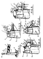
- an assembly suitable for use as a road traffic barrier comprises a rail 1 having one end of a flexible tether 2 secured thereto, a post 3 in the form of a cone with an enlarged base 4, and a locking element 5 for the tether 2 adapted to form part of a road hazard warning system such as a lamp 6 for mounting on top of the post 3.
- a road hazard warning system such as a lamp 6 for mounting on top of the post 3.
- the locking element 5 which forms a part of the present invention, will be able to fulfil the dual function of locking the warning system 5 and of securing the tether to the post 3. It is not a requirement of the invention, however, that this be the case.
- the post 3 as shown in Fig. 1 is preferably tubular and may, for example, be a tubular plastics upright, the base 4 of which may be a container closable by a removable plug or cover so that liquid ballast or particulate or friable solid ballast can be introduced therein.
- the post 3 has a substantially cylindrical portion 7 to which the rail 1 is attached by means of the tether 2, as will be described below, and which co-operates with the locking element 5.
- the rail 1 has one end of a flexible tether 2, such as a rope, attached thereto and the free end of the tether 2 is provided with an enlarged head, in the form of a toggle 8.
- the upper cylindrical portion 7 of the post 3 is provided with a pair of apertures 9 and 10.
- the aperture 9 comprises a circular hole of dimensions sufficiently large to permit the passage of the toggle 8 therethrough.
- the aperture 10, however, is in the shape of an inverted keyhole and is open at the top to provide a slot in the rim 11 of the post 3.
- the toggle 8 cannot pass through the aperture 10 but the tether 2 being of reduced dimensions can be threaded into the aperture 10 downwardly from the rim 11 of the post 3.
- the toggle 8 In order to attach the rail 1 to the post 3, the toggle 8 is firstly passed through the aperture 9 into the interior of the post 3, as indicated in Fig. 2. The toggle 8 is then pulled out of the top of the post 3 and the attached tether 2 slotted into the aperture 10, the toggle 8 then abuts the rim 11 of the aperture 10 on the exterior of the post 3.
- the rail 1 is hence supported by the tether 2 which is attached to the post 3 and can be releasably locked thereto by the locking element 5.
- the element 5 As shown in Fig. 4, the element 5 is designed to locate in the interior of the cylindrical portion 7 of the post. The actual locking mechanism employed to secure the element 5 to the post 3 is described below with reference to Fig. 8.
- the element 5 forms a cap which closes the open end of the post 3 around the rim 11. It is, therefore, not possible to unfasten the tether 2 from the post 3 as the aperture 10 has been restricted by the element 5 closing the open end thereof and the toggle 8 is unable to pass through the aperture 10.
- the only way of disengaging the rail 1 from the post 3 when the locking element 5 is in position is to sever the tether 2.
- the tether 2 is preferably made from a tough plastics material.
- Fig. 5 shows a second embodiment of the invention wherein the upper cylindrical portion 7 of the post 3 is provided with only a single aperture 12.
- the flexible tether 2 is secured to the rail 1 and has a free end with an enlarged head in the form of a toggle 8.
- the toggle 8 has a substantially rectangular end portion 13 and the aperture 12 is of a similar shape so that in one orientation, the toggle 8 can be passed through the aperture 12 into the interior of the post 3 but when then rotated through 90° cannot be withdrawn therefrom.
- the locking element 5 As in the first embodiment, once the rail 1 has been attached to the post 3, the locking element 5 same and thereby lock the toggle 8 in position by restricting the aperture 12. As shown in Fig. 7, in this embodiment the locking element 5 is preferably provided with a depending lug 14 which covers the upper portion of the aperture 12 and reduces its size such that the toggle 8 cannot then pass through in any orientation with respect to the aperture 12.
- the third embodiment of post and rail assembly shown in Fig. 6 is similar to the second embodiment described above with reference to Fig. 5.
- the upper cylindrical portion 7 of the post 3 is provided with a slot 15 which is open at its upper end in the rim 11 of the post 3.
- the flexible tether 2 is attached to the rail 1, as before, but the toggle 8 does not have a special shape, as in the second embodiment described above, but is of a size which is incapable of passing through the slot 15.
- the tether 2 adjacent the toggle 8 is threaded into the slot 15 so that the toggle 8 holds the tether 2 by abutment against the edge of the slot 15 on the interior of the post 3.
- a locking element similar to as previously described with reference to Fig. 7 can then be located in the post 3 to lock the toggle 8 in position.
- a depending lug provided on the element covers the top portion of the slot 15 to prevent removal of the tether 2 therefrom.
- the locking element 5 of Fig. 8 includes an upstanding portion 5a to which for example a lamp (not shown) may be secured.
- Engageable abutment means 16 are provided on the lower portion of the element 5 and on the interior of the post 3.
- a metal strip 18 Secured to the interior of a recess 17 formed in the interior wall surface of the post 3 is a metal strip 18. The strip 18 is bent and secured to the post 3 at one end only so that it forms a leaf spring depending downwardly into the post 3 and is resiliently biased towards the interior of the post 3.
- an abutment means in the form of a pair of outwardly projecting clips 19 located side by side on the lower edge of the element 5.
- the clips 19 are formed in the shape of an arrow head so that they each have a flat surface 20 extending outwardly from the element 5 at an acute angle which terminates with a second flat surface 21 projecting substantially normally from the adjacent surface of the element 5.
- the surfaces 20 of the clips 19 bear against the spring 18 and displace it to allow location of the element 5 in the post 3.
- the recess 17 defines, with the adjacent surface of the element 5, a pocket at the base of which is located the abutment means 16.
- a key 23, as shown in Fig. 8 must be used.
- the pocket therefore, protects the locking arrangement but allows access thereto for the key 23.
- a channel 24 may be formed in the exterior surface of the element 5 adjacent the recess 17. The channel 24 runs between the clips 19 and is designed to assist in the correct location of the key 23 in the pocket.
- the key 23 comprises a flexible plastics strip formed with a handle 25 at one end of a slender shank 26 and a wedge-shaped head 27 at the other end.
- the width of the head 27 is designed so that it can slide within the channel 24.
- the depth of the head 27 is designed to be greater than the combined depth of the surfaces 21 of the clips 19 and the depth of the channel 24.
- the head of the key 23 is inserted into the channel 24 and pushed downwardly into the pocket.
- the wedge-shaped head 27, being of greater dimensions than the clips 19, as described above, acts on the spring 18 so that the lower edge 22 of the spring 18 is biased away from the adaptor 3 and eventually clear of the edge of the surfaces 21. When this occurs, the element 5 can then be lifted out of the post 3 along with the key 23.
- the abutment means 16 could be arranged to be accessed by the key 23 through a hole or aperture formed in the cylindrical part 2 of the post 3.
- the post and rail assembly of the present invention provides a means of creating, for example, a road traffic barrier which is easy to set up and substantially vandal proof. Additionally, the provision of a locking element disengageable from the post 3 by means of a key allows the assembly to be set up and taken down easily, when required.
Landscapes
- Engineering & Computer Science (AREA)
- Architecture (AREA)
- Civil Engineering (AREA)
- Structural Engineering (AREA)
- Road Signs Or Road Markings (AREA)
- Refuge Islands, Traffic Blockers, Or Guard Fence (AREA)
Claims (4)
- Assemblage à montant et lisse comprenant une lisse (1) à laquelle l'une des extrémités d'une longe flexible (2) est attachée, un montant (3) présentant une partie (7) supérieure à extrémité ouverte et pourvue d'une ouverture (9) dans laquelle la longe (2) flexible peut être insérée, l'autre extrémité de la longe (2) étant pourvue d'une tête (8) élargie qui dans au moins une orientation au sein de l'ouverture (9) est incapable de passer à travers celle-ci, une unité de signalisation (5, 6) capable d'engagement dégageable avec le montant (3), et un moyen (5a, 16, 17, 18, 19) de blocage pour bloquer l'unité (5, 6) de signalisation dans la partie (7) supérieure creuse du montant (3), le moyen (5a, 16, 17, 18, 19) de blocage étant dégageable au moyen d'une clé (23) qui est capable d'être inséré dans la partie (7) supérieure creuse du montant (3), caractérisé en ce que ladite ouverture (9) s'étend à travers la paroi de la partie (7) supérieure creuse à extrémité ouverte du montant (3), et l'unité (5, 6) de signalisation est pourvue d'un corps (5) qui est capable d'être inséré dans la partie (7) supérieure creuse du montant (3) et qui lorsqu'il est inseré ainsi empêche l'enlèvement de la tête (8) élargie hors de ladite ouverture (9).
- Assemblage à montant et lisse selon la revendication 1, dans lequel le montant est pourvu d'une ouverture supplémentaire à travers laquelle on peut faire passer la tête élargie avant que la longe ne soit passée à travers ladite ouverture et que le moyen de blocage ne soit engagé avec le montant.
- Assemblage à montant et lisse selon la revendication 1 ou 2, dans lequel ladite ouverture comprend une fente qui est ouverte à une extrémité afin de permettre à la longe mais non pas à la tête élargie d'être passée à travers celle-ci.
- Assemblage à montant et lisse selon l'une quelconque des revendications précédentes, dans lequel l'élément de blocage comprend un moyen de butée capable d'engagement avec un second moyen de butée sollicité de manière résiliente et monté sur le montant.
Applications Claiming Priority (2)
| Application Number | Priority Date | Filing Date | Title |
|---|---|---|---|
| GB878718857A GB8718857D0 (en) | 1987-08-08 | 1987-08-08 | Post & rail assembly |
| GB8718857 | 1987-08-08 |
Publications (2)
| Publication Number | Publication Date |
|---|---|
| EP0303414A1 EP0303414A1 (fr) | 1989-02-15 |
| EP0303414B1 true EP0303414B1 (fr) | 1992-04-22 |
Family
ID=10622046
Family Applications (1)
| Application Number | Title | Priority Date | Filing Date |
|---|---|---|---|
| EP88307272A Expired - Lifetime EP0303414B1 (fr) | 1987-08-08 | 1988-08-05 | Assemblage montant et lisse |
Country Status (4)
| Country | Link |
|---|---|
| US (1) | US4944493A (fr) |
| EP (1) | EP0303414B1 (fr) |
| DE (1) | DE3870354D1 (fr) |
| GB (2) | GB8718857D0 (fr) |
Families Citing this family (13)
| Publication number | Priority date | Publication date | Assignee | Title |
|---|---|---|---|---|
| GB8818133D0 (en) * | 1988-07-29 | 1988-09-01 | Aph Road Safety Ltd | Improvement relating to road workings |
| GB2211233A (en) * | 1988-12-23 | 1989-06-28 | Barry Higginson | A security post |
| GB9125735D0 (en) * | 1991-11-30 | 1992-01-29 | Glasdon Ltd | A post and rail assembly |
| GB2282620B (en) * | 1993-09-02 | 1997-02-05 | Cook Peter Int Plc | A barrier system |
| US5467548A (en) * | 1994-07-27 | 1995-11-21 | Ross; Charles N. | Protective barrier members for work areas |
| WO1996032542A2 (fr) * | 1995-04-12 | 1996-10-17 | Frank Myers | Ensembles barriere |
| DE19801398A1 (de) * | 1998-01-16 | 1999-07-22 | Bosch Gmbh Robert | Radialkolbenpumpe zur Kraftstoffhochdruckversorgung |
| US5934651A (en) * | 1998-11-12 | 1999-08-10 | Koljonen; Reino | Wildlife barrier |
| US20050284097A1 (en) * | 2001-09-18 | 2005-12-29 | Outdoor Merchandising Solutions, Llc | System and method for localizing a zone |
| US6637971B1 (en) * | 2001-11-01 | 2003-10-28 | Worcester Polytechnic Institute | Reusable high molecular weight/high density polyethylene guardrail |
| US8087846B2 (en) * | 2009-03-16 | 2012-01-03 | James Ringelberg | Bollard configured to store a bollard coupling |
| GB2568175B (en) * | 2016-05-16 | 2019-11-06 | Absolute Museum & Gallery Products Ltd | A barrier stand |
| GB2550354B (en) * | 2016-05-16 | 2019-04-03 | Absolute Museum & Gallery Products Ltd | A barrier stand |
Family Cites Families (12)
| Publication number | Priority date | Publication date | Assignee | Title |
|---|---|---|---|---|
| US2648761A (en) * | 1951-09-28 | 1953-08-11 | John W Shamel | Street barricade light securing means |
| US3332117A (en) * | 1965-05-10 | 1967-07-25 | Norco Inc | Releasable cable fastener |
| US3643923A (en) * | 1969-07-15 | 1972-02-22 | Christian H Kirchhoff Jr | Paddock |
| FR2082627A5 (fr) * | 1970-03-18 | 1971-12-10 | Jodet Eugene | |
| US3732842A (en) * | 1971-05-10 | 1973-05-15 | A Vara | Road safety device and accessories |
| US3891189A (en) * | 1974-01-28 | 1975-06-24 | Michael T Russo | Link chain support post |
| GB1531725A (en) * | 1975-10-31 | 1978-11-08 | Glasdon Ltd | Post and rail assemblies |
| GB2052602A (en) * | 1979-06-01 | 1981-01-28 | Record A | Fencing posts |
| US4281524A (en) * | 1980-02-05 | 1981-08-04 | Linder Peter J | Key-controlled lock for a barrier cable |
| GB2102466B (en) * | 1981-06-10 | 1985-03-27 | Marler Haley Exposystems Ltd | Barrier systems |
| GB2147986B (en) * | 1983-10-14 | 1987-05-28 | Glasdon Ltd | Lockable lamp unit and barrier arrangement |
| US4787602A (en) * | 1987-05-01 | 1988-11-29 | Glasdon Limited | Tethers/anchorage assemblies |
-
1987
- 1987-08-08 GB GB878718857A patent/GB8718857D0/en active Pending
-
1988
- 1988-08-05 GB GB8818611A patent/GB2207942B/en not_active Expired - Lifetime
- 1988-08-05 EP EP88307272A patent/EP0303414B1/fr not_active Expired - Lifetime
- 1988-08-05 DE DE8888307272T patent/DE3870354D1/de not_active Expired - Lifetime
- 1988-08-08 US US07/229,937 patent/US4944493A/en not_active Expired - Fee Related
Also Published As
| Publication number | Publication date |
|---|---|
| GB2207942B (en) | 1992-01-08 |
| GB8818611D0 (en) | 1988-09-07 |
| GB2207942A (en) | 1989-02-15 |
| GB8718857D0 (en) | 1987-09-16 |
| DE3870354D1 (de) | 1992-05-27 |
| US4944493A (en) | 1990-07-31 |
| EP0303414A1 (fr) | 1989-02-15 |
Similar Documents
| Publication | Publication Date | Title |
|---|---|---|
| EP0303414B1 (fr) | Assemblage montant et lisse | |
| US4649397A (en) | Theft deterrent tag | |
| US20090095500A1 (en) | Tamper resistant locking cap for utility poles and method | |
| US5052198A (en) | Battery lock and hold-down device | |
| US4727900A (en) | Tamper-proof hydrant cover | |
| US3417508A (en) | Parking space barrier | |
| US5601278A (en) | Picket fence | |
| US20080264116A1 (en) | Multiple padlock lock system | |
| US5520479A (en) | Removable security post assembly | |
| US4915336A (en) | Adaptor and supporting container primarily for a lamp unit | |
| AU2002234780B2 (en) | Adjustable fence panel and method of assembly | |
| US5350150A (en) | Wall mounting bracket for carrying case | |
| US6138978A (en) | Flag pole mounting base | |
| US3277676A (en) | Ski lock | |
| US4475309A (en) | Modular protective grill | |
| US5803438A (en) | Plastic fencing | |
| US20040069520A1 (en) | Device for fixing distribution boxes | |
| US6416248B1 (en) | Quick release delineator apparatus | |
| US5905216A (en) | Track flag holder | |
| WO2008154568A1 (fr) | Bollard semi-permanent | |
| JPH0639741A (ja) | 窃盗防止具を取外すための取外装置 | |
| EP0070843B1 (fr) | Dispositif de maintien d'un extincteur | |
| US4495727A (en) | Anti-theft window bar | |
| US5653890A (en) | Bicycle storage system | |
| US5020840A (en) | Gate latch |
Legal Events
| Date | Code | Title | Description |
|---|---|---|---|
| PUAI | Public reference made under article 153(3) epc to a published international application that has entered the european phase |
Free format text: ORIGINAL CODE: 0009012 |
|
| AK | Designated contracting states |
Kind code of ref document: A1 Designated state(s): BE DE FR IT NL |
|
| 17P | Request for examination filed |
Effective date: 19890302 |
|
| 17Q | First examination report despatched |
Effective date: 19900509 |
|
| GRAA | (expected) grant |
Free format text: ORIGINAL CODE: 0009210 |
|
| AK | Designated contracting states |
Kind code of ref document: B1 Designated state(s): BE DE FR IT NL |
|
| ITF | It: translation for a ep patent filed | ||
| REF | Corresponds to: |
Ref document number: 3870354 Country of ref document: DE Date of ref document: 19920527 |
|
| ET | Fr: translation filed | ||
| PGFP | Annual fee paid to national office [announced via postgrant information from national office to epo] |
Ref country code: DE Payment date: 19920824 Year of fee payment: 5 |
|
| PGFP | Annual fee paid to national office [announced via postgrant information from national office to epo] |
Ref country code: FR Payment date: 19920827 Year of fee payment: 5 |
|
| PGFP | Annual fee paid to national office [announced via postgrant information from national office to epo] |
Ref country code: NL Payment date: 19920831 Year of fee payment: 5 |
|
| PGFP | Annual fee paid to national office [announced via postgrant information from national office to epo] |
Ref country code: BE Payment date: 19920918 Year of fee payment: 5 |
|
| PLBE | No opposition filed within time limit |
Free format text: ORIGINAL CODE: 0009261 |
|
| STAA | Information on the status of an ep patent application or granted ep patent |
Free format text: STATUS: NO OPPOSITION FILED WITHIN TIME LIMIT |
|
| 26N | No opposition filed | ||
| PG25 | Lapsed in a contracting state [announced via postgrant information from national office to epo] |
Ref country code: BE Effective date: 19930831 |
|
| BERE | Be: lapsed |
Owner name: GLASDON GROUP LTD Effective date: 19930831 |
|
| PG25 | Lapsed in a contracting state [announced via postgrant information from national office to epo] |
Ref country code: NL Effective date: 19940301 |
|
| NLV4 | Nl: lapsed or anulled due to non-payment of the annual fee | ||
| PG25 | Lapsed in a contracting state [announced via postgrant information from national office to epo] |
Ref country code: FR Effective date: 19940429 |
|
| PG25 | Lapsed in a contracting state [announced via postgrant information from national office to epo] |
Ref country code: DE Effective date: 19940503 |
|
| REG | Reference to a national code |
Ref country code: FR Ref legal event code: ST |
|
| PG25 | Lapsed in a contracting state [announced via postgrant information from national office to epo] |
Ref country code: IT Free format text: LAPSE BECAUSE OF NON-PAYMENT OF DUE FEES;WARNING: LAPSES OF ITALIAN PATENTS WITH EFFECTIVE DATE BEFORE 2007 MAY HAVE OCCURRED AT ANY TIME BEFORE 2007. THE CORRECT EFFECTIVE DATE MAY BE DIFFERENT FROM THE ONE RECORDED. Effective date: 20050805 |