EP0303376A2 - Pumpe für Gemenge mit empfindlichem Material - Google Patents
Pumpe für Gemenge mit empfindlichem Material Download PDFInfo
- Publication number
- EP0303376A2 EP0303376A2 EP88307032A EP88307032A EP0303376A2 EP 0303376 A2 EP0303376 A2 EP 0303376A2 EP 88307032 A EP88307032 A EP 88307032A EP 88307032 A EP88307032 A EP 88307032A EP 0303376 A2 EP0303376 A2 EP 0303376A2
- Authority
- EP
- European Patent Office
- Prior art keywords
- chamber
- inlet
- outlet
- source
- valve
- Prior art date
- Legal status (The legal status is an assumption and is not a legal conclusion. Google has not performed a legal analysis and makes no representation as to the accuracy of the status listed.)
- Withdrawn
Links
Images


Classifications
-
- F—MECHANICAL ENGINEERING; LIGHTING; HEATING; WEAPONS; BLASTING
- F04—POSITIVE - DISPLACEMENT MACHINES FOR LIQUIDS; PUMPS FOR LIQUIDS OR ELASTIC FLUIDS
- F04F—PUMPING OF FLUID BY DIRECT CONTACT OF ANOTHER FLUID OR BY USING INERTIA OF FLUID TO BE PUMPED; SIPHONS
- F04F1/00—Pumps using positively or negatively pressurised fluid medium acting directly on the liquid to be pumped
- F04F1/02—Pumps using positively or negatively pressurised fluid medium acting directly on the liquid to be pumped using both positively and negatively pressurised fluid medium, e.g. alternating
-
- A—HUMAN NECESSITIES
- A01—AGRICULTURE; FORESTRY; ANIMAL HUSBANDRY; HUNTING; TRAPPING; FISHING
- A01K—ANIMAL HUSBANDRY; AVICULTURE; APICULTURE; PISCICULTURE; FISHING; REARING OR BREEDING ANIMALS, NOT OTHERWISE PROVIDED FOR; NEW BREEDS OF ANIMALS
- A01K79/00—Methods or means of catching fish in bulk not provided for in groups A01K69/00 - A01K77/00, e.g. fish pumps; Detection of fish; Whale fishery
Definitions
- the present invention relates to a pump for pumping a slurry of frail material, more particularly the present invention relates simplified control system and an improved pump incorporating a suction and pressure cycle.
- the inlet and outlet valves used in this system are check valves which open and close depending on the pressure in the chamber. This arrangement was found to be unsatisfactory in practice as fish did not always clear the check valves and if the valve attempted to close with a fish caught therein the fish would either prevent closing of the valve rendering the pump inoperative or would be cut or damaged in some way to permit closing thereby reducing the value of the fish.
- Bladder valves, or as they are sometimes called, pinch valves have been in use for many years in various industries but never in connection with pumping frail material. Examples of such bladder valves are shown in United States Patent 4,268,005 issued May 19 1981 to Raftis et al or United States patent 4,135,550 issued January 23 1975 to Anderson.
- frail material as used in the present disclosure is intended to describe material that may be demaged by valves or its value reduced when caught in a valve and interfere with the valve as it is closing, in particular food products such as fish, vegetables, fruit and the like.
- the present invention relates to a pump for pumping a slurry of frail material
- a pump for pumping a slurry of frail material comprising a rigid closed chamber having an inlet means including an inlet opening opening into chamber and inlet conduit extending from said inlet opening and away from said chamber, an outlet means including an outlet opening opening into said chamber adjacent the bottom of said chamber when said chamber is in operative position and an outlet conduit communicating with said outlet opening and extending from said outlet opening away from said chamber, an inlet valve means controlling flow through said inlet means and an outlet valve means controlling flow through said outlet means, means to connect a source of positive or a source of negative air pressure to the interior of said chamber, control means controlling the application of said positive and negative pressures to said chamber and controlling the opening and closing of said inlet and outlet valve means and sensing means for sensing the amount of said slurry in said chamber at least when said chamber is filled to a preselected degree, said sensing means when said sensed amount reaches a preset maximum indicating said chamber is full to the required
- At least said outlet valve means will comprise a bladder valve and most preferably both said inlet and said outlet valve means will each comprise a bladder valve.
- the sensing means is a weight sensing means which preferably is incorporated in a cable system by which the chamber is suspended so that the total weight of the chamber and contents is determined by sensing the tension in said cable system.
- the sensing means comprises means for sensing the level of slurry in the chamber for example by a float valve in said chamber closing a passage through which air is withdrawn when said chamber is connected to said source of negative air pressure to cause the pressure in said passage to decrease and sensing said decreased pressure to trigger said controller means.
- the pump 10 generally comprises a rigid chamber 12 having extending from one end thereof an inlet conduit 14 opening directly into the chamber 12 and from the opposite end thereof an outlet conduit 16.
- Suitable inlet and outlet valves 18 and 20 are provided one in the inlet and outlet conduits respectively.
- Extending from the ends of the valves 18 and 20 remote from the chamber 12 are suitable flexible pipes or the like 22 and 24 respectively.
- the pipe 22 leads to an inlet shoe 26 and the outlet pipe 24 carries the slurry being pumped (eg. a slurry of fish) to the desired destination.
- various fluid plumbing lines illustrated by the lines 28,30 and 32 are connected respectively to the chamber 12 and the valves 18 and 20 to provide positive or negative pressure within the chamber 12 and to open and close the valves 18 and 20.
- the pump 10 of figure 1 is suspended from a boom or the like 34 through or along which the various lines 28, 30 and 32 pass to connect with the fluid pumps (not shown) and control valves.
- the pump 10 is suspended from the boom 34 via a tension cable 36 having interposed intermediate its length a sensor 38 adapted to sense the tension between the upper section 36 of the cable and the lower section 40 which is on the opposite side of the sensor 38. Any suitable weight sensor 38 may be used.
- the signal generated by the sensor 38 is carried on the dot dash line 42 to the controller 70 as will be explained in detail hereinbelow.
- tension cables 44, 46 and 48 are connected to an annular ring or flange 50 on the upper end of the chamber 12.
- the sensor 38 carries essentially the full weight of the unit and thus it will sense the weight thereof.
- the degree of submergence of the piping to and from the chamber and the extraneous support of this piping may contribute to or detract from the weight sensed by the sensor 38 and for this reason the set point that triggers the operation of the controller (to be described below) is adjustable easily to vary the setting as desired to accommodate any particular arrangement. It is not essential that the preset triggering weight be particularly accurate in absolute terms.
- One simple way of setting the preselected weight is to use the sensor to sense the weight of the empty chamber and set the preset weight a selected amount higher than the weight empty.
- the chamber 12 of pump 10 has its bottom substantially horizontal or sloped slightly downward toward the outlet and it is fixed to fixed platform 52 with suitable sensors 54 and 56 positioned in the mounting (only two sensor are shown).
- the signal representative of the weight of the chamber 12 is transmitted via line 58 (equivalent to line 42) to the controller as will be described hereinbelow.
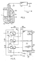
- FIG. 3 An alternative triggering system for the controller 70 is illustrated in Figure 3.
- the weight sensor is eliminated and a simple float valve is used such as the ball 51 held within the cage 53 at the connection of piping 28 into the chamber 12 to seal off this connection when the chamber 12 is filled to the required extent.
- the ball 51 moves vertically in the cage 53 between the position illustrated by the dotted line at the bottom of the cage 53 and wherein the conduit 28 is connected to the chamber 12 and the position illustrated in a solid line wherein the ball 51 cooperates with the seat 55 to seal off the conduit 28 and prevent further withdrawal of air from the chamber 12.
- the pump 10 has been shown in section ilustrating the hollow chamber 12 with the outlet conduit 16 projecting downward therein and terminating in an open end 60 located adjacent the lower or bottom end of chamber 12 which is adjacent the inlet conduit 14.
- a rounded bead or the like 61 will be provided at the mouth 60 of the outlet pipe 16 to facilitate movement of the frail material from the inside of the chamber 12 through the mouth 60 and into the conduit 16.
- valve 18 In the arrangement shown in Figure 4 pressure has been applied to the chamber 62 of the bladder valve 20 to force the valve 20 into a closed position wherein the bladder 64 which is some form of collapsible flexible tubular member is collapsed into the closed position as illustrated.
- the valve 18 is shown in open position and the chamber 68 of this valve may be under negative or neutral pressure, depending on the structure of the bladder 66 to hold the bladder in open condition as a tubular member.
- the open position as illustrated for valve 18 is the stable or neutral position requiring no negative pressure with positive pressure only being necessary to collapse the bladder to closed position. Both the valves 18 and 20 may have the same structure.
- valves 18 Because these are relatively large valves necessary to handle the flows of slurry of frail materials it is preferred to apply negative pressure to the operating chamber 68 of the valve 18 when the valve is in its open position to counteract the negative pressure applied from the chamber 12 and tending to close the valve 18 when the chamber 12 is under negative pressure conditions.
- the valve 20 is not open when the chamber 12 is under negative pressure conditions and will only be open (when the pump is operating) when the chamber 12 is under a positive air pressure and therefor is not subject to being sucked to closed position by negative pressure in the chamber 12.
- the sensor 38 or 54 and 56 or 57 is used to trigger the controller 70 which controls the control valves 72, 74 and 76 in the lines 28,30 and 32 respectively as indicated by the dot dash lines 78,80 and 82 respectively.
- These valves connect their respective lines 28,30 and 32 to the a source of suction i.e. negative pressure as indicated by the arrow 84 via line 86, or depending on the bladder structures of the valves 18 and 20, the valves 74 and 76 may be connected to the vents 92 or 93 instead of line 84 as will be described below.
- a single source of air under positive pressure indicated by arrow 88 and connecting line 90 has been illustrated, but if required the air pressure applied in chamber 12 may be reduced relative to the air pressure provided to close the valve 18 or 20.
- the system illustrated in Figure 4 operates as follows. On start-up of the pump 10 the outlet valve 20 is closed or moved to closed position i.e. in the position as illustrated in Figure 4 and thus the valve 76 is operative to connect the positive pressure in line 90 to the line 32 and thus move the bladder 64 in valve 20 to the closed position shown. At the same time the valve 74 depending on the type of bladder 66 in valve 18 connects line 30 either to the negative pressure in line 86 or to the vent 92 i.e. if negative pressure in the chamber 68 of valve 18 is not necessary to maintain the valve 18 in open position then line 30 need only be vented as will normally be the case. In the latter case the line 86 need not be connected to the valve 74 and only the vent 92 need be provided.
- the valve 72 then connects the line 28 to the negative pressure line 86 thereby withdrawing air from the inside of the chamber 12 which draws the slurry of frail material eg. water and fish up through the pipe 22, valve 18 and inlet conduit 14 into the inside of the chamber 12 to fill the chamber 12 with a slurry of fish and water.
- the sensor 38 (54,56) or 57 senses when the amount of slurry in the chamber 12 reaches the desired level. When a preset amount is sensed by the sensor 38 or (54,56) or 57, and the chamber is deemed to be full, the controller 70 is triggered. The controller 70 then activates the valve 72 to disconnect the line 28 from the line 86 and the source of negative pressure 84 and thereby disconnect the chamber 12 from the source of negative pressure.
- the chamber 12 is disconnected from the source of air under negative pressure when the ball 51 is seated in the seat 55.
- the valve 74 is then actuated to connect the line 30 to the source of positive air pressure 88 via line 90 and thereby close the valve 18. It is important that the pressure in the chamber 12 not be permitted to rise significantly before the valve 18 is fully closed, thus the chamber 12 cannot be connected to the source of positive pressure 88 unless the valve 18 is closed.
- the operating chamber 68 of valve 18 fills with fluid and collapses the bladder 66 to a closed position and thereby closes valve 18 substantially as illustrated for valve 20 in Figure 4.
- the rate of flow of slurry through the valve 18 (or 20) should be substantially stopped or at least significantly reduced before the valve 18 (or 20) is closed to avoid damaging the valve as it is closing due to the movement of the slurry therethrough. This closes off the inlet so that no further movement of fish into the chamber 12 can occur.
- the pressure exhaust portion of the pumping cycle then commences.
- the valve 72 now connects the inside of chamber 12 to the source of air under positive pressure 88 to raise the pressure in the chamber 12.
- the valve 76 is then actuated to either connect the line 32 to the source of negative pressure as indicated at 84 via line 86 or to connect the chamber 62 to vent 93 depending on the type of bladder used in the valve 20 as described hereinabove with respect to the valve 18.
- the fish slurry is thereby forced around the element 61 and into the inlet 60 of the outlet conduit 16 and out through the outlet and pipe 24.
- the controller 70 controls the times between the operations of the various valves as required.
- the duration of the predetermined period of time when the pressure is introduced into the chamber 12 may be adjusted as indicated by knob 96 on a timer 94 which forms part of the controller 70 and thereby control the amount of slurry moved from the chamber 12 i.e. the cycle capacity of the pump and to insure that air does not pass into the outlet conduit 16 in the pressure portion of the cycle.
- valve 72 disconnects the chamber 12 from the source of positive air pressure 88 and may move into a neutral position where neither positive nor negative air pressure is applied to the chamber i.e. the line 28 is sealed.
- the valve 76 now again connects line 32 to the positive pressure line 90 thereby to inflate the bladder 64 of valve 20 back to the closed position as illustrated in Figure 4, and then the valve 72 is then operated to connect the chamber to the source of air at negative pressure and reduce the pressure in the chamber 12.
- the chamber 12 should remain at positive pressure until the valve 20 closes to prevent the slurry from flowing back toward the chamber 12 through the valve 20, yet the pressure should be reduced somewhat so that flow through the valve 20 will at least be slowed to an appropriate rate before the valve 20 is moved to closed position otherwise damage to the solids in the slurry or even to the valve might occur if the valve 20 were moved to the closed position with the slurry flowing therethrough at too fast a rate.
- valve 72 then connects the chamber 12 to the source of negative air pressure 84 and the valve 74 is then actuated to connect the line 30 to the vent 92 or the line 86 depending as above described on the type of bladder to move the bladder 66 to the position shown in Figure 4 i.e. to open the valve 18 and repeat the pumping cycle.
- the triggering weight indicating that the chamber 12 is full may can be adjusted. This adjustment may be made by the controller 70 as indicated by the knob 100.
- valves 74 and 76 use an incompressible fluid such as water to move the valve bladders 64 and 66 to closed position.
- water under pressure will be available from a source as indicated by the arrow 102 in line 104 which is connected to the valve 74 via line 106 and to valve 76 via line 108. If the valves 18 and 20 when not subjected to pressure in their respective chambers will automatically return to the open position it is only necessary to provide a vent as indicated by line 110 and arrow 112. If desired a pump may be provided for line 110 to cause the flow as indicated by the arrow 112 and apply a negative pressure tending to hold the valves in open position.
- valve 18 It may be necessary to apply reduced pressure to the operating chamber 68 of the valve 18 when the valve 18 is in open position to hold the valve 18 open. If the valve is connected to the source of negative pressure as in line 84 of Figure 4 no other means is necessary, but where the valve chamber 66 is connected to a vent such negative pressure, if required, may be obtained, for example, by interconnecting the interiors of the operating chamber 68 of the valve 18 and of the chamber 12 when the valve 18 is in open position to substantially balance the pressure on opposite sides of the bladder 66.
- a timer 94 is used to initiate shifting of the valve 72 to the position disconnecting the chamber 12 from the high pressure line 90 and closing the valve 20 thereby terminating the pumping of the fish through the outlet conduit 16 when the chamber has been properly exhausted of fish yet before exhaustion of air from the chamber 12 into the outlet conduit 16.
- the weight sensor 38 (54,56) may also be used for this purpose in place of the timer 94 by simply having a lower threshold i.e. one determining a minimum weight (a predetermined amount above the empty weight of the chamber 12 etc. to insure that the level of fish slurry in the chamber 12 does not expose the inlet 60 to air).
- both the upper weight threshold and lower weight threshold will require adjustment on set up and therefore a second adjustment as indicated by the knob 144 or 116 may be provide either on the weight sensor 38 (54,56) or controller 70 respectively.
- a second adjustment as indicated by the knob 144 or 116 may be provide either on the weight sensor 38 (54,56) or controller 70 respectively.
- sensing the lower threshold will trigger causing the reduction of pressure in the chamber 12 eg. by the disconnecting of the chamber 12 from the positive pressure source 88 and the closing of the valve 20, with the timing of the other operations being essentially the same.
- a pressure sensor 300 is provided to sense the pressure at the top of the vessel or chamber 12 and a second pressure sensor 302 sense the pressure at the bottom of the chamber 12.
- the sensors 300 and 302 are connected to a unit 304 via line 306 and 308 respectively.
- the unit 304 determines the difference in the pressures at the top and bottom of the chamber 12 as sensed by the sensors 300 and 302 respectively and provide an indication of the weight of slurry in the chamber 12.
- the unit 304 is connected to the controller 70 via the line 310 to transmit this information to the controller 70.
- the controller 70 is actuated to commence the pressure or exhaust portion of the pumping cycle i.e. the negative pressure source is disconnected from the chamber 12, the valve 20 closed etc. Termination of the pressure portion of the pumping cycle may be initiated by the timer 94 or by the unit 304 sensing a lower weight threshold.
- the sensor 300 and 302 were described as pressure sensors, but as one alternative, they could be any suitable type of level sensors sensing the level of slurry in the chamber 12.
- the sensors 300 and 302 could be hot point sensors that measure the temperature of a heated probe, the temperature of which changes significantly depending on whether the it is submerged or not. Change in probe temperature indicates that the level of slurry has past the location of the probe.
- the top sensor 300 is necessary if the timer 94 is used to time the output of the pump (pressure portion of the pumping cycle).
Landscapes
- Engineering & Computer Science (AREA)
- Life Sciences & Earth Sciences (AREA)
- Mechanical Engineering (AREA)
- General Engineering & Computer Science (AREA)
- Environmental Sciences (AREA)
- Marine Sciences & Fisheries (AREA)
- Animal Husbandry (AREA)
- Biodiversity & Conservation Biology (AREA)
- Reciprocating Pumps (AREA)
- Jet Pumps And Other Pumps (AREA)
Applications Claiming Priority (2)
| Application Number | Priority Date | Filing Date | Title |
|---|---|---|---|
| US07/082,508 US4770610A (en) | 1987-08-07 | 1987-08-07 | Frail material slurry pump |
| US82508 | 2001-10-19 |
Publications (2)
| Publication Number | Publication Date |
|---|---|
| EP0303376A2 true EP0303376A2 (de) | 1989-02-15 |
| EP0303376A3 EP0303376A3 (de) | 1989-06-07 |
Family
ID=22171654
Family Applications (1)
| Application Number | Title | Priority Date | Filing Date |
|---|---|---|---|
| EP88307032A Withdrawn EP0303376A3 (de) | 1987-08-07 | 1988-07-29 | Pumpe für Gemenge mit empfindlichem Material |
Country Status (7)
| Country | Link |
|---|---|
| US (1) | US4770610A (de) |
| EP (1) | EP0303376A3 (de) |
| JP (1) | JPS6463666A (de) |
| CA (1) | CA1281593C (de) |
| DK (1) | DK431188A (de) |
| NO (1) | NO883508L (de) |
| RU (1) | RU1794202C (de) |
Cited By (2)
| Publication number | Priority date | Publication date | Assignee | Title |
|---|---|---|---|---|
| FR2702802A1 (fr) * | 1993-03-15 | 1994-09-23 | Cat | Pompe à dépression et surpression pour débiter des quantités prédéterminées de produits. |
| RU2623855C1 (ru) * | 2016-09-19 | 2017-06-29 | Федеральное государственное бюджетное образовательное учреждение высшего образования "Санкт-Петербургский государственный технологический институт (технический университет)" | Устройство для газлифтного транспортирования |
Families Citing this family (12)
| Publication number | Priority date | Publication date | Assignee | Title |
|---|---|---|---|---|
| EP0352941A3 (de) * | 1988-07-29 | 1991-09-18 | Innovac Technology Inc. | Gerät und Verfahren zur Durchflusssteuerung |
| US5002463A (en) * | 1988-07-29 | 1991-03-26 | Innovac Technology Inc. | Apparatus and method for flow control |
| US5011376A (en) * | 1990-04-05 | 1991-04-30 | Henriksson Kurt K G | Valve control system for an air displacement type pump |
| DE4232361A1 (de) * | 1992-09-26 | 1994-03-31 | Ieg Ind Engineering Gmbh | Fördervorrichtung für empfindliche Flüssigkeiten, beispielsweise für biologische Kläranlagen |
| US6224345B1 (en) | 1999-03-22 | 2001-05-01 | Bijur Lubrication Corporation | pressure/vacuum generator |
| JP2003205462A (ja) * | 2002-01-11 | 2003-07-22 | Tokyo Seimitsu Co Ltd | Cmp研磨装置における研磨剤の調合装置及び調合方法 |
| WO2006037186A1 (en) * | 2004-10-08 | 2006-04-13 | Supavac Pty Ltd | Pump apparatus |
| AU2005291860B2 (en) * | 2004-10-08 | 2010-08-19 | Poche Engineering Pty Ltd | Pump apparatus |
| JP2008544761A (ja) * | 2005-07-01 | 2008-12-11 | エムピーエフ,インク. | 結合組織からタンパク質を分離するシステム及び方法 |
| US9102392B2 (en) * | 2010-12-15 | 2015-08-11 | The Boeing Company | Method and apparatus for air flow control in an aircraft sidewall volume |
| US9717258B2 (en) | 2014-10-28 | 2017-08-01 | Cooke Aquaculture Inc. | Constant diameter pumping system and method |
| US10555510B2 (en) | 2014-10-28 | 2020-02-11 | Cooke Aquaculture Inc. | Fish pumping system and method |
Family Cites Families (15)
| Publication number | Priority date | Publication date | Assignee | Title |
|---|---|---|---|---|
| US2596593A (en) * | 1947-12-08 | 1952-05-13 | Ind Res Inc | Pressure jet apparatus |
| US2943578A (en) * | 1956-12-13 | 1960-07-05 | Megator Pumps Compressor | Pumps of the air displacement type |
| DE1131994B (de) * | 1956-12-13 | 1962-06-20 | Megator Pumps Compressor | Mit Druckmittelverdraengung arbeitende Pumpe |
| US3007416A (en) * | 1958-08-13 | 1961-11-07 | Gen Dynamics Corp | Pump for cellular fluid such as blood and the like |
| US3573934A (en) * | 1968-07-19 | 1971-04-06 | Grace W R & Co | Method for transporting and storing aquatic fauna and preserving the same |
| US3583365A (en) * | 1969-03-21 | 1971-06-08 | Darrel G Harden | Method and apparatus for handling fish |
| US3701618A (en) * | 1971-01-27 | 1972-10-31 | Donald G Wall | Peristaltic extrusion press |
| US3871332A (en) * | 1972-10-28 | 1975-03-18 | Kyoei Zoki Kk | Apparatus for sucking up and transferring fishes |
| US4135550A (en) * | 1977-03-11 | 1979-01-23 | Trelleborg Rubber Company, Inc. | Pinch valve control circuit |
| US4181470A (en) * | 1977-11-18 | 1980-01-01 | Gillett Bruce F | Gas-operated liquid pump |
| US4268005A (en) * | 1978-12-08 | 1981-05-19 | Red Valve Company, Inc. | Pinch valve |
| US4222496A (en) * | 1979-01-22 | 1980-09-16 | Fabri-Coate Company, Inc. | Continuous outflow, weight-measuring blender |
| US4316702A (en) * | 1980-03-17 | 1982-02-23 | Electronic Systems Division, Geosource, Inc. | Oil well control circuit |
| DD159661A1 (de) * | 1981-06-15 | 1983-03-23 | Bernd Glueck | Einrichtung zur fluessigkeitsfoerderung mit minimierter kompressibler druckmedienmenge |
| US4517099A (en) * | 1983-10-07 | 1985-05-14 | Breckner Raymond A | Apparatus and method for handling solids in liquid |
-
1987
- 1987-08-07 US US07/082,508 patent/US4770610A/en not_active Expired - Fee Related
-
1988
- 1988-07-15 CA CA000572231A patent/CA1281593C/en not_active Expired - Lifetime
- 1988-07-29 EP EP88307032A patent/EP0303376A3/de not_active Withdrawn
- 1988-08-02 DK DK431188A patent/DK431188A/da not_active Application Discontinuation
- 1988-08-05 NO NO88883508A patent/NO883508L/no unknown
- 1988-08-05 JP JP63197028A patent/JPS6463666A/ja active Pending
- 1988-08-05 RU SU884356392A patent/RU1794202C/ru active
Cited By (3)
| Publication number | Priority date | Publication date | Assignee | Title |
|---|---|---|---|---|
| FR2702802A1 (fr) * | 1993-03-15 | 1994-09-23 | Cat | Pompe à dépression et surpression pour débiter des quantités prédéterminées de produits. |
| WO1994021924A1 (fr) * | 1993-03-15 | 1994-09-29 | C.A.T. Cybernetique Automatisme Telecommunication S.A.R.L. | Pompe a depression et surpression pour debiter des quantites predeterminees de produits |
| RU2623855C1 (ru) * | 2016-09-19 | 2017-06-29 | Федеральное государственное бюджетное образовательное учреждение высшего образования "Санкт-Петербургский государственный технологический институт (технический университет)" | Устройство для газлифтного транспортирования |
Also Published As
| Publication number | Publication date |
|---|---|
| NO883508L (no) | 1989-02-08 |
| EP0303376A3 (de) | 1989-06-07 |
| CA1281593C (en) | 1991-03-19 |
| RU1794202C (ru) | 1993-02-07 |
| JPS6463666A (en) | 1989-03-09 |
| NO883508D0 (no) | 1988-08-05 |
| DK431188D0 (da) | 1988-08-02 |
| US4770610A (en) | 1988-09-13 |
| DK431188A (da) | 1989-02-08 |
Similar Documents
| Publication | Publication Date | Title |
|---|---|---|
| CA1281593C (en) | Frail material slurry pump | |
| US5495725A (en) | Water transfer assembly for water cooler | |
| US5293893A (en) | Empty drum detecting apparatus | |
| US4828461A (en) | Apparatus for metering flowable materials in sand core making machines | |
| US5665601A (en) | Avoiding bubble formation while sensing air-liquid interface using pressurized air flow | |
| JP3102891B2 (ja) | 真空下水搬送システム用水だめ通気制御機構 | |
| US4315760A (en) | Method and apparatus for degasing, during transportation, a confined volume of liquid to be measured | |
| EP0214206B1 (de) | Verfahren und mittel zur verwendung beim pumpen und bei volumetrischer analyse von flüssigkeiten | |
| US3434430A (en) | Self-priming pump system with external actuating means | |
| US5715856A (en) | Liquid flow control apparatus | |
| US4255079A (en) | Self-priming system for pumps | |
| US5022114A (en) | Device for suctioning up and removing a contaminated liquid | |
| US2457863A (en) | Air charger | |
| US2347472A (en) | dorward | |
| JPH05141365A (ja) | 流体圧装置 | |
| US4028011A (en) | Low well yield control system | |
| US3062149A (en) | Impeller pump pressure system and pump unit assembly therefor | |
| US2839001A (en) | Air volume control mechanism | |
| US3035522A (en) | Pumps | |
| JPH03102218A (ja) | 水管柱の水位を連続的に探知し、さらにモーター駆動式ポンプの始動および停止を予め設定された最高および最低水位で連続的に操作するための空気圧式装置 | |
| US3047009A (en) | Bottom loading valve mechanism | |
| CN111200931A (zh) | 自动平衡的家禽水分配系统 | |
| JP2946011B2 (ja) | 水位制御装置 | |
| JP3007791B2 (ja) | 液状物等流体の自動移送装置 | |
| US3056422A (en) | Water level control device |
Legal Events
| Date | Code | Title | Description |
|---|---|---|---|
| PUAI | Public reference made under article 153(3) epc to a published international application that has entered the european phase |
Free format text: ORIGINAL CODE: 0009012 |
|
| AK | Designated contracting states |
Kind code of ref document: A2 Designated state(s): DE ES FR GB NL |
|
| PUAL | Search report despatched |
Free format text: ORIGINAL CODE: 0009013 |
|
| AK | Designated contracting states |
Kind code of ref document: A3 Designated state(s): DE ES FR GB NL |
|
| 17P | Request for examination filed |
Effective date: 19891020 |
|
| 17Q | First examination report despatched |
Effective date: 19900810 |
|
| STAA | Information on the status of an ep patent application or granted ep patent |
Free format text: STATUS: THE APPLICATION HAS BEEN WITHDRAWN |
|
| 18W | Application withdrawn |
Withdrawal date: 19920701 |