EP0303366A1 - Anschluss-T-Stück zur Verbindung mit einer Gas- oder Wasserhauptrohrleitung - Google Patents
Anschluss-T-Stück zur Verbindung mit einer Gas- oder Wasserhauptrohrleitung Download PDFInfo
- Publication number
- EP0303366A1 EP0303366A1 EP88306798A EP88306798A EP0303366A1 EP 0303366 A1 EP0303366 A1 EP 0303366A1 EP 88306798 A EP88306798 A EP 88306798A EP 88306798 A EP88306798 A EP 88306798A EP 0303366 A1 EP0303366 A1 EP 0303366A1
- Authority
- EP
- European Patent Office
- Prior art keywords
- hole
- plug
- expander
- side branch
- main
- Prior art date
- Legal status (The legal status is an assumption and is not a legal conclusion. Google has not performed a legal analysis and makes no representation as to the accuracy of the status listed.)
- Withdrawn
Links
Images


Classifications
-
- F—MECHANICAL ENGINEERING; LIGHTING; HEATING; WEAPONS; BLASTING
- F16—ENGINEERING ELEMENTS AND UNITS; GENERAL MEASURES FOR PRODUCING AND MAINTAINING EFFECTIVE FUNCTIONING OF MACHINES OR INSTALLATIONS; THERMAL INSULATION IN GENERAL
- F16L—PIPES; JOINTS OR FITTINGS FOR PIPES; SUPPORTS FOR PIPES, CABLES OR PROTECTIVE TUBING; MEANS FOR THERMAL INSULATION IN GENERAL
- F16L41/00—Branching pipes; Joining pipes to walls
- F16L41/04—Tapping pipe walls, i.e. making connections through the walls of pipes while they are carrying fluids; Fittings therefor
-
- Y—GENERAL TAGGING OF NEW TECHNOLOGICAL DEVELOPMENTS; GENERAL TAGGING OF CROSS-SECTIONAL TECHNOLOGIES SPANNING OVER SEVERAL SECTIONS OF THE IPC; TECHNICAL SUBJECTS COVERED BY FORMER USPC CROSS-REFERENCE ART COLLECTIONS [XRACs] AND DIGESTS
- Y10—TECHNICAL SUBJECTS COVERED BY FORMER USPC
- Y10S—TECHNICAL SUBJECTS COVERED BY FORMER USPC CROSS-REFERENCE ART COLLECTIONS [XRACs] AND DIGESTS
- Y10S285/00—Pipe joints or couplings
- Y10S285/901—Cap closures
-
- Y—GENERAL TAGGING OF NEW TECHNOLOGICAL DEVELOPMENTS; GENERAL TAGGING OF CROSS-SECTIONAL TECHNOLOGIES SPANNING OVER SEVERAL SECTIONS OF THE IPC; TECHNICAL SUBJECTS COVERED BY FORMER USPC CROSS-REFERENCE ART COLLECTIONS [XRACs] AND DIGESTS
- Y10—TECHNICAL SUBJECTS COVERED BY FORMER USPC
- Y10T—TECHNICAL SUBJECTS COVERED BY FORMER US CLASSIFICATION
- Y10T137/00—Fluid handling
- Y10T137/0318—Processes
- Y10T137/0402—Cleaning, repairing, or assembling
- Y10T137/0441—Repairing, securing, replacing, or servicing pipe joint, valve, or tank
- Y10T137/0447—Including joint or coupling
-
- Y—GENERAL TAGGING OF NEW TECHNOLOGICAL DEVELOPMENTS; GENERAL TAGGING OF CROSS-SECTIONAL TECHNOLOGIES SPANNING OVER SEVERAL SECTIONS OF THE IPC; TECHNICAL SUBJECTS COVERED BY FORMER USPC CROSS-REFERENCE ART COLLECTIONS [XRACs] AND DIGESTS
- Y10—TECHNICAL SUBJECTS COVERED BY FORMER USPC
- Y10T—TECHNICAL SUBJECTS COVERED BY FORMER US CLASSIFICATION
- Y10T137/00—Fluid handling
- Y10T137/0318—Processes
- Y10T137/0402—Cleaning, repairing, or assembling
- Y10T137/0441—Repairing, securing, replacing, or servicing pipe joint, valve, or tank
- Y10T137/0458—Tapping pipe, keg, or tank
- Y10T137/0463—Particular aperture forming means
-
- Y—GENERAL TAGGING OF NEW TECHNOLOGICAL DEVELOPMENTS; GENERAL TAGGING OF CROSS-SECTIONAL TECHNOLOGIES SPANNING OVER SEVERAL SECTIONS OF THE IPC; TECHNICAL SUBJECTS COVERED BY FORMER USPC CROSS-REFERENCE ART COLLECTIONS [XRACs] AND DIGESTS
- Y10—TECHNICAL SUBJECTS COVERED BY FORMER USPC
- Y10T—TECHNICAL SUBJECTS COVERED BY FORMER US CLASSIFICATION
- Y10T137/00—Fluid handling
- Y10T137/598—With repair, tapping, assembly, or disassembly means
- Y10T137/612—Tapping a pipe, keg, or apertured tank under pressure
- Y10T137/6123—With aperture forming means
-
- Y—GENERAL TAGGING OF NEW TECHNOLOGICAL DEVELOPMENTS; GENERAL TAGGING OF CROSS-SECTIONAL TECHNOLOGIES SPANNING OVER SEVERAL SECTIONS OF THE IPC; TECHNICAL SUBJECTS COVERED BY FORMER USPC CROSS-REFERENCE ART COLLECTIONS [XRACs] AND DIGESTS
- Y10—TECHNICAL SUBJECTS COVERED BY FORMER USPC
- Y10T—TECHNICAL SUBJECTS COVERED BY FORMER US CLASSIFICATION
- Y10T137/00—Fluid handling
- Y10T137/598—With repair, tapping, assembly, or disassembly means
- Y10T137/612—Tapping a pipe, keg, or apertured tank under pressure
- Y10T137/613—With valved closure or bung
- Y10T137/6133—Combined rotary and longitudinal movement of valve
Definitions
- the present invention relates to a service tee for connection to a gas or water main whereby to effect subsequent fluid communication between the main and a service pipe.
- a service tee of the type comprising a tubular T-piece having a through-portion with a flexible end for connection to a gas or water main by way of a hole in the wall of the main and a side branch portion for connection to a service pipe, the end of the through-portion being adapted for initial insertion into the hole in the wall of the main and then for subsequent radial outward expansion so that its surface sealingly engages with the edge of the hole, an expander for location within the end of the through-portion and adapted in a first position to permit the initial insertion of the end of the through-portion into the hole and on movement to a second position to cause the expansion of the end into engagement with the edge of the hole, and a plug engagable with the expander and adapted to move the expander from its first to its second position, the arrangement being that after expansion the plug can be moved from a first position where the end of the through-portion is closed off from the side branch portion to a second position where the side branch portion and the
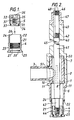
- the service tee comprises a tubular T-piece 1 having a through-portion 2 and a side branch portion 3, an expander 4 and plug 5.
- the T-piece itself is of a generally flexible material such as plastics, preferably polyethylene.
- the through-portion 2 comprises a first lower end 6 for receiving the expander 4 and for connection to a gas or water main and a second upper end 7 from which the side branch portion 3 extends radially.
- the bore of the lower end 6 is generally larger than that of the upper end 7 and tapers slightly inwardly in the upward direction to form a shoulder 8 at the junction with the upper end 7.
- the outer wall 10 of the through-position 2 is also provided with an annular rib 11 level with the shoulder 8 for purposes to be described.
- a part 12 of the outer wall 10 of the through-portion 2 adjacent the opening in the upper end 7 is also threaded for a purpose also to be described.
- the expander 4 is tubular and is of metal, for example mild steel.
- the outer diameter of the expander 4 tapers inwardly in an upward direction and is such that on being inserted into the lower end 6 of the through-portion 2 and on being raised within the lower end 6, the latter is caused to be distorted radially outwardly.
- the outer wall 21 of the expander 4 has an annular rib 22 for engaging the inner wall of the lower end 6 of the through-portion 2.
- the rib 22 provides a boundary between a lowermost part 23 of the outer wall 21 of the expander 4 and an uppermost part 24 of the outer wall 21.
- the uppermost part 24 of the wall 21 is as shown in Figure 2 dimensioned to fit within the lower end 6 with the lowermost part 23 of the expander 4 being dimensioned to cause gradual radial expansion of the lower end 6.
- the lowermost part 23 of the expander wall 21 terminates in an annular flange 25 which in use provides a limit to the upward movement of the expander 4 by eventually engaging with the circumferential lower edge of the lower end 6 of the through-portion 2.
- the inner wall 26 of the expander 4 has an internally threaded portion 27 to receive and retain the plug 5 and forms at its lowermost end an annular shoulder 28 to retain the plug 5 as will subsequently be described.
- the plug 5 is generally cylindrical and has an outer wall 31 having a larger diameter threaded uppermost part 32 to engage the threaded inner wall portion 27 of the expander 4 and a smaller diameter lowermost part 33 which in use fits within the annular shoulder 28 of the expander 4.
- the lowermost part 33 has an annular recess containing an O-ring 34 forming a seal with the expander shoulder 28.
- a blind hole 35 Extending axially into the plug body 5 from its uppermost surface is a blind hole 35 which has an entry portion 36 in the form of an hexagonal key-hole and an innermost portion 37 having a partly-threaded wall.
- the threads in the portion 37 are left-hand and as will be shown permit the plug 5 to be engaged by a first tool to be described serving to raise the expander 4 within the lower end 6 of the T-piece through-portion 2 when the plug 5 has been threadedly located within the expander 4 and the latter is inserted within the lower end 6 of the T-piece through portion 2.
- the key-hole portion 36 permits the plug 5 to be engaged by a second tool to be described serving to unscrew the plug from the expander 4 and then screw it up into the upper end 7 of the through-portion 2 past the junction with the side branch portion 3 as will be subsequently described.
- the first tool 40 comprises an assembly of a shaft 41 and a tubular sleeve 42 in which the shaft 41 can be mounted for axial slidable movement.
- the shaft 41 comprises a lowermost portion 43, the end 44 of which is threaded with left hand threads for engagement with the threaded portion 37 of the plug hole 35.
- the shaft 41 also comprises an uppermost portion 45 which is of slightly larger diameter than the lowermost portion 43 and has a threaded end 46 on which may be screwed a flanged nut 47.
- the threaded end 46 terminates in a square head 48 to permit the shaft 41 to be engaged by a spanner to screw the shaft 41 into or out of the plug.
- the sleeve 42 comprises adjoining uppermost and lowermost portions 49 and 50, the ends 45,46 of the shaft protruding beyond their respective sleeve portions 49,50.
- the uppermost sleeve portion 49 has a bore with which the uppermost shaft portion 45 is a close slidable fit to maintain the axial alignment of the shaft 41.
- the lowermost sleeve portion 50 has a bore which is dimensioned to permit the portion 50 to fit closely over the upper end 7 of the T-piece through-portion 2 as shown in Figures 2 and 3, the sleeve portion 50 having a slot 51 extending upwardly from its lowermost edge so as in use to permit the sleeve portion 50 to fit over the side branch portion 3. In use the lowermost edge of the sleeve portion 50 abuts the annular rib 11 of the through-portion 2.
- the flanged nut 47 in use bears against the uppermost edge of the sleeve portion 49 so that when the nut 47 is rotated in the appropriate direction the shaft 41 is raised.
- the second tool 60 comprises an assembly of a shaft 61 and a sleeve 62 in which the shaft 61 can be slidably mounted.
- the shaft 61 has a threaded lower end 63 adapted to engage the threaded portion 37 of the blind hole 35 in the plug 5.
- the upper end of the shaft 61 terminates in a to permit the shaft 61 to be finger-screwed into and out of the plug 5.
- the knob 64 has a knurled edge 65 to enable it to be gripped firmly with the fingers.
- the sleeve 62 has a tubular body 66 dimensioned to fit closely within the bore of the T-piece through-portion 2, which body 66 terminates at its lower end in an hexagonal key portion 67 adapted to engage in the corresponding key-hole 36 in the plug hole 35.
- the key-portion 67 is apertured centrally to allow the threaded end 63 of the shaft 61 to extend therethrough.
- the body 66 is also provided adjacent its uppermost end with two radially directed but opposite handles 68,69 to permit the sleeve 62 to be rotated about its axis to screw the plug 5 upwardly into the through-portion 2 as will be subsequently described.
- the service tee may be connected to a gas or water main in the following manner.
- a suitable hole is drilled in the wall of the gas or water main 70 (figures 3 to 5) using a standard under-pressure drilling machine (not shown) in combination with a standard plate valve (not shown) temporarily connected to the wall of the main 70. After the hole has been drilled, the machine is removed and the plate in the plate valve is closed.
- the plug 5 is then screwed down into the expander 4 until the plug O-ring 34 forms a fluid tight seal with the expander shoulder 28 (as for example shown in Figures 2 to 4).
- the plug 5 may be screwed tightly into the plug 5 by means of the key portion 67 of the sleeve part 62 in tool 60, the tool shaft 61 having been temporarily removed.
- a plastics material eg. polythene tee saddle 71 of known type ( Figure 2) shaped to conform to the main 70 is push-fitted onto the lower end 6 of the T-piece through-portion 2 until it engages with the lowermost edge of the annular rib 11, the saddle 71 being dimensioned to leave a depending portion of the through-portion lower end 6 for insertion into the hole in the main 70.
- Figure 2 A plastics material eg. polythene tee saddle 71 of known type ( Figure 2) shaped to conform to the main 70 is push-fitted onto the lower end 6 of the T-piece through-portion 2 until it engages with the lowermost edge of the annular rib 11, the saddle 71 being dimensioned to leave a depending portion of the through-portion lower end 6 for insertion into the hole in the main 70.
- the plate valve is then opened and the lower end 6 of the service tee is inserted into the hole in the main 70.
- the flanged nut 47 is then rotated in a direction which causes the shaft 41 to be lifted thus forcing the expander 4 to travel up inside the lower end 6 of the through-portion 2 and cause the lower end 6 to flexible outwardly to seal against the edge of the hole - the position shown in Figure 3.
- the connection between the tee and the main has been made.
- the flanged nut 47 is then removed from the upper end 46 of the shaft 41 and this latter is unscrewed from the plug 5 and removed together with the sleeve 42.
- the sleeve 62 (with the shaft 61 temporarily removed) is lowered into the bore of the through-portion 2 through the opening in the upper end 7 and its key-portion 67 is located in the key-hole portion 36 of the plug 5.
- the shaft 61 is then fitted into the bore of the sleeve 62 and its threaded end 63 is located in the threaded portion 37 of the plug-hole 5 so as to centre the tool sleeve 62 - the position shown in Figure 4.
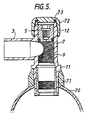
- the tool sleeve 62 is then rotated by the handles 68,69 in a direction causing the plug 5 to be screwed upwardly into the threaded bore of the through-portion 2 and finally into the position shown in Figure 5 ie. at a point in the upper end 7 of the through-portion 2 past the service branch portion 3. Communication is now established between the through-portion 2 and the service branch portion 3 to which of course, a service pipe will have already been suitably connected. Finally an internally threaded sealing cap 72 is screwed onto the upper end 7 of the through-portion 2 as shown in Figure 5 to form a seal with the uppermost circumferential edge of the through-portion 2 by means of the internal O-ring seal 73.
Applications Claiming Priority (2)
| Application Number | Priority Date | Filing Date | Title |
|---|---|---|---|
| GB8718360A GB2207725B (en) | 1987-08-03 | 1987-08-03 | A service tee for connection to a gas or water main |
| GB8718360 | 1987-08-03 |
Publications (1)
| Publication Number | Publication Date |
|---|---|
| EP0303366A1 true EP0303366A1 (de) | 1989-02-15 |
Family
ID=10621752
Family Applications (1)
| Application Number | Title | Priority Date | Filing Date |
|---|---|---|---|
| EP88306798A Withdrawn EP0303366A1 (de) | 1987-08-03 | 1988-07-25 | Anschluss-T-Stück zur Verbindung mit einer Gas- oder Wasserhauptrohrleitung |
Country Status (4)
| Country | Link |
|---|---|
| US (1) | US4922951A (de) |
| EP (1) | EP0303366A1 (de) |
| CA (1) | CA1312894C (de) |
| GB (1) | GB2207725B (de) |
Families Citing this family (8)
| Publication number | Priority date | Publication date | Assignee | Title |
|---|---|---|---|---|
| GB2254119B (en) * | 1991-03-28 | 1995-01-11 | Kubota Kk | Corrosion-preventive sleeve for hole in metal pipe and tool for mounting the same |
| US5479955A (en) * | 1994-05-31 | 1996-01-02 | Spartanburg Steel Products, Inc. | Method and apparatus for aseptically filling containers |
| US5577776A (en) * | 1995-05-03 | 1996-11-26 | Tdw Deleware, Inc. | Tee fitting for lined pipe |
| US5695222A (en) * | 1996-01-31 | 1997-12-09 | James Bruno | Ratchet type closet flange |
| EP1463901A4 (de) * | 2001-12-12 | 2007-01-03 | Martinrea Ind Inc | Stutzenanordnung für einen kraftfahrzeugtank |
| US6871401B1 (en) | 2002-08-06 | 2005-03-29 | Tool for inserting and removing a corporation stop and method for use thereof | |
| CN103353037B (zh) * | 2013-07-12 | 2016-09-07 | 宁波志清实业有限公司 | 一片式三通及其切换成二片式三通的方法 |
| KR102181687B1 (ko) * | 2019-05-20 | 2020-11-23 | 신영석 | 천공탭이 내장된 이형관 및 이를 이용한 천공방법 |
Citations (2)
| Publication number | Priority date | Publication date | Assignee | Title |
|---|---|---|---|---|
| DE2536000A1 (de) * | 1974-08-12 | 1976-03-04 | Dresser Ind | T-abzweig fuer plastikrohre |
| GB2051991A (en) * | 1979-07-03 | 1981-01-21 | British Gas Corp | Method of and apparatus for making a connection to a pipe |
Family Cites Families (7)
| Publication number | Priority date | Publication date | Assignee | Title |
|---|---|---|---|---|
| GB236308A (en) * | 1924-04-14 | 1925-07-09 | Stone J & Co Ltd | Improvements in and connected with pipe joints and connections |
| FR1160843A (fr) * | 1956-11-14 | 1958-08-11 | Dispositif perfectionné d'assemblage pour les prises de branchement sur les conduites de distribution de fluides | |
| US3349792A (en) * | 1965-02-24 | 1967-10-31 | Phillips Petroleum Co | Tapping t and valve |
| GB1139435A (en) * | 1966-08-01 | 1969-01-08 | Edward Barber & Company Ltd | Improvements in and relating to taps or valves for liquid or gas flow control |
| US3554217A (en) * | 1969-04-21 | 1971-01-12 | Sealed Unit Parts Co Inc | Self-tapping valve |
| US3995655A (en) * | 1975-10-07 | 1976-12-07 | Mueller Co. | Apparatus for and method of making a service line connection through a fitting |
| GB2103321B (en) * | 1981-08-05 | 1985-09-11 | Barber And Company Limited Edw | Tapping pipe connections |
-
1987
- 1987-08-03 GB GB8718360A patent/GB2207725B/en not_active Expired - Fee Related
-
1988
- 1988-07-25 EP EP88306798A patent/EP0303366A1/de not_active Withdrawn
- 1988-07-26 US US07/224,148 patent/US4922951A/en not_active Expired - Lifetime
- 1988-08-02 CA CA000573601A patent/CA1312894C/en not_active Expired - Fee Related
Patent Citations (2)
| Publication number | Priority date | Publication date | Assignee | Title |
|---|---|---|---|---|
| DE2536000A1 (de) * | 1974-08-12 | 1976-03-04 | Dresser Ind | T-abzweig fuer plastikrohre |
| GB2051991A (en) * | 1979-07-03 | 1981-01-21 | British Gas Corp | Method of and apparatus for making a connection to a pipe |
Also Published As
| Publication number | Publication date |
|---|---|
| GB2207725B (en) | 1991-02-13 |
| CA1312894C (en) | 1993-01-19 |
| US4922951A (en) | 1990-05-08 |
| GB8718360D0 (en) | 1987-09-09 |
| GB2207725A (en) | 1989-02-08 |
Similar Documents
| Publication | Publication Date | Title |
|---|---|---|
| US3995655A (en) | Apparatus for and method of making a service line connection through a fitting | |
| US5425395A (en) | Tapping tee assembly | |
| EP1350008B8 (de) | Muffenventil zur steuerung von fluidströmung zwischen einem kohlenwasserstoffspeicher und einer rohrleitung in einem bohrloch und verfahren zum montage eines muffenventils | |
| US4922951A (en) | Service tee for connection to a gas or water main | |
| US20130257036A1 (en) | Tube couplings | |
| EP0380196B1 (de) | Sicherheitsverbindung für Zuführungen in rohrförmigen Körpern | |
| US4144909A (en) | Apparatus for closing side openings into pipelines | |
| US4400020A (en) | Pressure tank connector | |
| EP0339156A2 (de) | Rohranschluss | |
| US3272211A (en) | Main and service line connection embodying a self-tapping nipple and an excessive-flow safety valve-method and apparatus | |
| US3045512A (en) | Service fitting | |
| US4791716A (en) | Method and apparatus for securing a connector to a pipe | |
| AU624116B2 (en) | Subsea tubular joint | |
| US3045511A (en) | Service t | |
| JP5147243B2 (ja) | サドル分水栓の止水装置およびその止水方法ならびにサドル分水栓の交換方法 | |
| US5000719A (en) | Retrievable sealing plug and method of making same | |
| US2336173A (en) | Service t | |
| US5216793A (en) | Hose fitting removal apparatus | |
| US2478508A (en) | Pipe joint | |
| CA2056234C (en) | Hose fitting removal apparatus | |
| JP3266890B2 (ja) | 水道管の分岐栓の取替方法及び該方法に用いる装置 | |
| GB2263744A (en) | Sealant head | |
| US5655283A (en) | Corporation stop assembly | |
| JP2799188B2 (ja) | プラスチック管の補修方法 | |
| DE3937690C1 (de) |
Legal Events
| Date | Code | Title | Description |
|---|---|---|---|
| PUAI | Public reference made under article 153(3) epc to a published international application that has entered the european phase |
Free format text: ORIGINAL CODE: 0009012 |
|
| AK | Designated contracting states |
Kind code of ref document: A1 Designated state(s): BE DE ES FR GB IT NL |
|
| 17P | Request for examination filed |
Effective date: 19890117 |
|
| 17Q | First examination report despatched |
Effective date: 19891129 |
|
| STAA | Information on the status of an ep patent application or granted ep patent |
Free format text: STATUS: THE APPLICATION IS DEEMED TO BE WITHDRAWN |
|
| 18D | Application deemed to be withdrawn |
Effective date: 19901124 |