EP0303342A1 - Assemblage de lentilles pour un système de balayage à laser - Google Patents
Assemblage de lentilles pour un système de balayage à laser Download PDFInfo
- Publication number
- EP0303342A1 EP0303342A1 EP88305546A EP88305546A EP0303342A1 EP 0303342 A1 EP0303342 A1 EP 0303342A1 EP 88305546 A EP88305546 A EP 88305546A EP 88305546 A EP88305546 A EP 88305546A EP 0303342 A1 EP0303342 A1 EP 0303342A1
- Authority
- EP
- European Patent Office
- Prior art keywords
- lens
- optical axis
- optical
- converging
- assembly
- Prior art date
- Legal status (The legal status is an assumption and is not a legal conclusion. Google has not performed a legal analysis and makes no representation as to the accuracy of the status listed.)
- Ceased
Links
- 230000003287 optical effect Effects 0.000 claims abstract description 110
- 230000005540 biological transmission Effects 0.000 claims abstract description 6
- 238000003384 imaging method Methods 0.000 claims description 3
- 238000010408 sweeping Methods 0.000 description 6
- 238000010276 construction Methods 0.000 description 2
- 239000000853 adhesive Substances 0.000 description 1
- 230000001070 adhesive effect Effects 0.000 description 1
- 230000004075 alteration Effects 0.000 description 1
- 230000000712 assembly Effects 0.000 description 1
- 238000000429 assembly Methods 0.000 description 1
- 230000007613 environmental effect Effects 0.000 description 1
- CPBQJMYROZQQJC-UHFFFAOYSA-N helium neon Chemical compound [He].[Ne] CPBQJMYROZQQJC-UHFFFAOYSA-N 0.000 description 1
- 238000012986 modification Methods 0.000 description 1
- 230000004048 modification Effects 0.000 description 1
- 239000002991 molded plastic Substances 0.000 description 1
Images

Classifications
-
- G—PHYSICS
- G06—COMPUTING; CALCULATING OR COUNTING
- G06K—GRAPHICAL DATA READING; PRESENTATION OF DATA; RECORD CARRIERS; HANDLING RECORD CARRIERS
- G06K7/00—Methods or arrangements for sensing record carriers, e.g. for reading patterns
- G06K7/10—Methods or arrangements for sensing record carriers, e.g. for reading patterns by electromagnetic radiation, e.g. optical sensing; by corpuscular radiation
- G06K7/10544—Methods or arrangements for sensing record carriers, e.g. for reading patterns by electromagnetic radiation, e.g. optical sensing; by corpuscular radiation by scanning of the records by radiation in the optical part of the electromagnetic spectrum
- G06K7/10821—Methods or arrangements for sensing record carriers, e.g. for reading patterns by electromagnetic radiation, e.g. optical sensing; by corpuscular radiation by scanning of the records by radiation in the optical part of the electromagnetic spectrum further details of bar or optical code scanning devices
- G06K7/10861—Methods or arrangements for sensing record carriers, e.g. for reading patterns by electromagnetic radiation, e.g. optical sensing; by corpuscular radiation by scanning of the records by radiation in the optical part of the electromagnetic spectrum further details of bar or optical code scanning devices sensing of data fields affixed to objects or articles, e.g. coded labels
- G06K7/10871—Methods or arrangements for sensing record carriers, e.g. for reading patterns by electromagnetic radiation, e.g. optical sensing; by corpuscular radiation by scanning of the records by radiation in the optical part of the electromagnetic spectrum further details of bar or optical code scanning devices sensing of data fields affixed to objects or articles, e.g. coded labels randomly oriented data-fields, code-marks therefore, e.g. concentric circles-code
Definitions
- the present invention generally relates to laser instruments and, more particularly, to a bifocal lens assembly adapted for use in a laser scanner system which, on the same optical axis, transmits light to a spaced target, such as a product carrying a bar code symbol, and detects light reflected from the target.
- One known bifocal lens assembly includes a large convex collection lens within which is formed a much smaller convex lens.
- the smaller lens is ordinarily positioned above the axis of the larger collection lens.
- the laser beam is sent from the source laser through the smaller convex lens and then through scanning optics to the bar code target.
- the light reflected from the target is collected and received, in a much larger volume, through the large collection lens and focused and directed to a photodetector.
- the laser beam is originally transmitted through the smaller lens not along the optical axis of the larger lens, while the reflected and collected light passes back through the larger lens along its optical axis.
- One known trifocal lens assembly of the above cross-referenced application includes a large collection lens having a first curved surface on the side which receives light reflected from a target and a second curved surface on the opposite side which faces a photodetector. Also, a small prism with a beam expander element thereon are integrally attached to and protrude outwardly from the second surface of the large collection lens, whereas a small focusing lens is formed on the first surface of lens. The small prism and beam expander element and the optical axis of the focusing lens are respectively disposed along and coaxial with the optical axis of the first and second surfaces of the large collection lens.
- the beam expander element of the trifocal lens assembly first receives the laser beam at an angle inclined to the optical axis of the collection lens, and expands the beam.
- the expanded beam is reflected by the prism and routed along the collection lens optical axis to the focusing lens.
- the focusing lens converges the expanded beam and focuses it at the target via intervening scanning optics.
- a substantial volume of light reflected from the target is received back, via intervening scanning optics again, by the collection lens which images and transmits the collected light along the optical axis of the lens to a photodetector.
- the third optical means is formed on the lens about the optical axis and on an opposite side thereof from the second optical means for converging and focusing the expanded laser beam at a substantial distance from the lens as it is transmitted therefrom.
- the third optical means may be a first converging lens portion formed on the lens on the opposite side thereof and aligned about the optical axis thereof.
- the converging lens portion has a convex curvature and is substantially smaller in diameter than the lens.
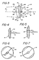
- the lens assembly 12 includes second and third optical means in the form of respective small diameter diverging and converging lens portions 34, 36 and fourth and fifth optical means in the form of large diameter converging lens portions 38, 40, all of which are integrally formed on respective opposite sides 42, 44 of the lens 14.
- the small diameter diverging lens portion 34 is formed on the inner side 42 of the lens 14 in alignment with the optical axis 16 thereof and has a diameter substantially smaller than that of the lens 14.
- the diverging lens portion 34 as best seen in Fig. 4, has a radius R1 extending from exterior of the lens 14 providing the lens portion 34 with slightly concave exterior curvature. As schematically shown in Fig. 3, due to such curvature the diverging lens portion 34 receives the laser beam 32 reflected by the mirror 28 and expands it into an expanded light beam 46 which travels through the lens 14.
Landscapes
- Physics & Mathematics (AREA)
- Engineering & Computer Science (AREA)
- Electromagnetism (AREA)
- Artificial Intelligence (AREA)
- Toxicology (AREA)
- General Health & Medical Sciences (AREA)
- Health & Medical Sciences (AREA)
- Computer Vision & Pattern Recognition (AREA)
- General Physics & Mathematics (AREA)
- Theoretical Computer Science (AREA)
- Lasers (AREA)
- Optical Radar Systems And Details Thereof (AREA)
- Lens Barrels (AREA)
Applications Claiming Priority (2)
| Application Number | Priority Date | Filing Date | Title |
|---|---|---|---|
| US07/063,540 US4786798A (en) | 1987-06-18 | 1987-06-18 | Beam forming and collection lens assembly for laser scanner system |
| US63540 | 1993-05-18 |
Publications (1)
| Publication Number | Publication Date |
|---|---|
| EP0303342A1 true EP0303342A1 (fr) | 1989-02-15 |
Family
ID=22049912
Family Applications (1)
| Application Number | Title | Priority Date | Filing Date |
|---|---|---|---|
| EP88305546A Ceased EP0303342A1 (fr) | 1987-06-18 | 1988-06-17 | Assemblage de lentilles pour un système de balayage à laser |
Country Status (3)
| Country | Link |
|---|---|
| US (1) | US4786798A (fr) |
| EP (1) | EP0303342A1 (fr) |
| JP (1) | JPS6420501A (fr) |
Cited By (1)
| Publication number | Priority date | Publication date | Assignee | Title |
|---|---|---|---|---|
| CN104900025A (zh) * | 2012-09-06 | 2015-09-09 | 苏州浩创信息科技有限公司上海物智信息分公司 | 数据采集器 |
Families Citing this family (21)
| Publication number | Priority date | Publication date | Assignee | Title |
|---|---|---|---|---|
| JPH03116391A (ja) * | 1989-06-29 | 1991-05-17 | Ncr Corp | デテクタ・アセンブリ |
| US5057687A (en) * | 1989-06-29 | 1991-10-15 | Ncr Corporation | Detector assembly with plural optical axes |
| US5187353A (en) * | 1990-04-18 | 1993-02-16 | Symbol Technologies, Inc. | Bar code symbol scanner utilizing monitor photodiode of laser diode package as a photoreceiver |
| US5233170A (en) * | 1990-04-18 | 1993-08-03 | Symbol Technologies, Inc. | Bar code symbol scanner utilizing monitor photodiode of laser diode package as a photoreceiver |
| US5438187A (en) * | 1991-11-01 | 1995-08-01 | Spectra-Physics Scanning Systems, Inc. | Multiple focus optical system for data reading applications |
| US5331140A (en) * | 1992-04-02 | 1994-07-19 | Xerox Corporation | Code reading systems |
| US5327451A (en) * | 1992-08-07 | 1994-07-05 | Spectra-Physics Scanning Systems, Inc. | Laser diode assembly for laser scanner system |
| US5347121A (en) * | 1992-12-18 | 1994-09-13 | Spectra-Physics Scanning Systems, Inc. | Variable focus optical system for data reading |
| US5479011A (en) * | 1992-12-18 | 1995-12-26 | Spectra-Physics Scanning Systems, Inc. | Variable focus optical system for data reading |
| JP3441580B2 (ja) * | 1995-12-14 | 2003-09-02 | 富士通株式会社 | 読取装置 |
| US5734157A (en) * | 1996-08-27 | 1998-03-31 | Liou; Kenneth | Bar-code optical scanner |
| US6166375A (en) | 1996-10-08 | 2000-12-26 | Psc Scanning, Inc. | Offset optical axes for bar code scanner |
| US6056198A (en) | 1997-08-07 | 2000-05-02 | Psc Scanning, Inc. | Optical scanning system and method including a collection system for range enhancement |
| US6290135B1 (en) | 1999-07-23 | 2001-09-18 | Psc Scanning, Inc. | Multiple source/dense pattern optical scanner |
| US6585161B1 (en) * | 2000-08-30 | 2003-07-01 | Psc Scanning, Inc. | Dense pattern optical scanner |
| US6578765B2 (en) | 2001-09-12 | 2003-06-17 | Psc Scanning, Inc. | Optical scanning system and integrated optics module therefor |
| US6752315B1 (en) * | 2002-12-19 | 2004-06-22 | Ncr Corporation | Detector assembly for use in a bar code scanner and methods for fabricating the same |
| US20080023550A1 (en) * | 2006-07-31 | 2008-01-31 | Ming Yu | Curved window in electro-optical reader |
| US20160216084A1 (en) * | 2015-01-22 | 2016-07-28 | Robert Louis Foege | Laser Light Activated Target |
| US10143474B2 (en) | 2015-05-08 | 2018-12-04 | Just Right Surgical, Llc | Surgical stapler |
| CN110376133A (zh) * | 2019-07-26 | 2019-10-25 | 徐州旭海光电科技有限公司 | 一种便携式气体探测仪用光学组件 |
Citations (4)
| Publication number | Priority date | Publication date | Assignee | Title |
|---|---|---|---|---|
| US4009369A (en) * | 1974-05-03 | 1977-02-22 | Schiller Industries, Inc. | Polyphase scanner for bar code symbols |
| US4136821A (en) * | 1976-09-01 | 1979-01-30 | Nippondenso Co., Ltd. | Method and apparatus for recognizing code information |
| EP0085804A2 (fr) * | 1982-01-25 | 1983-08-17 | Symbol Technologies, Inc. | Tête d'exploration portable à laser, au corps étroit, à fenêtre simple et double, pour la lecture de symboles en code à barres |
| EP0137966A2 (fr) * | 1983-08-22 | 1985-04-24 | Optel Systems, Inc. | Dispositif optique pour détecter des symboles codés |
Family Cites Families (6)
| Publication number | Priority date | Publication date | Assignee | Title |
|---|---|---|---|---|
| US3481672A (en) * | 1967-01-03 | 1969-12-02 | Hughes Aircraft Co | F.m. laser contour mapper |
| US3994008A (en) * | 1974-01-02 | 1976-11-23 | Polaroid Corporation | Camera accessory mount |
| NL181693C (nl) * | 1974-11-29 | 1987-10-01 | Philips Nv | Inrichting voor het langs optische weg uitlezen van een stralingsreflekterende registratiedrager. |
| US4496831A (en) * | 1980-02-29 | 1985-01-29 | Symbol Technologies, Inc. | Portable laser scanning system and scanning methods |
| US4678288A (en) * | 1984-04-27 | 1987-07-07 | Spectra-Physics, Inc. | Trifocal lens for a laser instrument |
| US4675531A (en) * | 1985-03-28 | 1987-06-23 | Polaroid Corporation | Optical scanner having a multi-surfaced lens arrangement for producing a rotationally symmetric beam |
-
1987
- 1987-06-18 US US07/063,540 patent/US4786798A/en not_active Expired - Lifetime
-
1988
- 1988-06-13 JP JP63145573A patent/JPS6420501A/ja active Granted
- 1988-06-17 EP EP88305546A patent/EP0303342A1/fr not_active Ceased
Patent Citations (4)
| Publication number | Priority date | Publication date | Assignee | Title |
|---|---|---|---|---|
| US4009369A (en) * | 1974-05-03 | 1977-02-22 | Schiller Industries, Inc. | Polyphase scanner for bar code symbols |
| US4136821A (en) * | 1976-09-01 | 1979-01-30 | Nippondenso Co., Ltd. | Method and apparatus for recognizing code information |
| EP0085804A2 (fr) * | 1982-01-25 | 1983-08-17 | Symbol Technologies, Inc. | Tête d'exploration portable à laser, au corps étroit, à fenêtre simple et double, pour la lecture de symboles en code à barres |
| EP0137966A2 (fr) * | 1983-08-22 | 1985-04-24 | Optel Systems, Inc. | Dispositif optique pour détecter des symboles codés |
Cited By (1)
| Publication number | Priority date | Publication date | Assignee | Title |
|---|---|---|---|---|
| CN104900025A (zh) * | 2012-09-06 | 2015-09-09 | 苏州浩创信息科技有限公司上海物智信息分公司 | 数据采集器 |
Also Published As
| Publication number | Publication date |
|---|---|
| JPH0575151B2 (fr) | 1993-10-19 |
| JPS6420501A (en) | 1989-01-24 |
| US4786798A (en) | 1988-11-22 |
Similar Documents
| Publication | Publication Date | Title |
|---|---|---|
| US4786798A (en) | Beam forming and collection lens assembly for laser scanner system | |
| US4678288A (en) | Trifocal lens for a laser instrument | |
| US5202784A (en) | Optical system for data reading applications | |
| US6292287B1 (en) | Scanning confocal optical device | |
| US4653880A (en) | Reflective beam splitting objective | |
| US5428438A (en) | Laser ranging and detection system employing a geometric coherent/incoherent beam separator | |
| EP0667549A2 (fr) | Système opto-mécanique | |
| CA2357927C (fr) | Systeme sans fil de transmission optique dans l'espace point a multipoint | |
| JP2920194B2 (ja) | 光学式走査装置 | |
| US5136422A (en) | Reflective optical system for a microscopic spectrometer | |
| US3371212A (en) | Light spot projection system for infrared camera | |
| US5274491A (en) | Dynamic laser diode aperture for optical scanners | |
| JPS60100113A (ja) | レ−ザ−ビ−ムプリンタ | |
| KR950033946A (ko) | 비점수차, 보우 왜곡 및 필드 곡률을 교정하기 위한 장치 및 그 방법 | |
| ES2110303T3 (es) | Dispositivo embarcable de medicion de retrodifusion de luz. | |
| JP2003196581A (ja) | 光学式情報読み取り装置 | |
| EP0405965A2 (fr) | Assemblage détecteur | |
| US5793514A (en) | Optical scanner for finite conjugate applications | |
| EP0100124A1 (fr) | Système optique d'autodirecteur à imagerie | |
| JPH07182439A (ja) | ベッセルビーム走査装置 | |
| US6281488B1 (en) | Fiber optic coupled optical sensor | |
| US6519386B1 (en) | Light coupling apparatus and method | |
| KR950015239A (ko) | 포커스 에러 검출장치 | |
| EP0709798A1 (fr) | Appareil de balayage du type béton avec un détecteur placé dans un trou de l'élément optique d'éclairage | |
| RU1804638C (ru) | Сканирующее устройство |
Legal Events
| Date | Code | Title | Description |
|---|---|---|---|
| PUAI | Public reference made under article 153(3) epc to a published international application that has entered the european phase |
Free format text: ORIGINAL CODE: 0009012 |
|
| AK | Designated contracting states |
Kind code of ref document: A1 Designated state(s): BE DE FR GB IT LU NL SE |
|
| 17P | Request for examination filed |
Effective date: 19890807 |
|
| 17Q | First examination report despatched |
Effective date: 19910904 |
|
| STAA | Information on the status of an ep patent application or granted ep patent |
Free format text: STATUS: THE APPLICATION HAS BEEN REFUSED |
|
| 18R | Application refused |
Effective date: 19930311 |