EP0302936A1 - Servo controller for a press machine - Google Patents
Servo controller for a press machine Download PDFInfo
- Publication number
- EP0302936A1 EP0302936A1 EP88900584A EP88900584A EP0302936A1 EP 0302936 A1 EP0302936 A1 EP 0302936A1 EP 88900584 A EP88900584 A EP 88900584A EP 88900584 A EP88900584 A EP 88900584A EP 0302936 A1 EP0302936 A1 EP 0302936A1
- Authority
- EP
- European Patent Office
- Prior art keywords
- ram
- speed
- press machine
- servomotor
- servo controller
- Prior art date
- Legal status (The legal status is an assumption and is not a legal conclusion. Google has not performed a legal analysis and makes no representation as to the accuracy of the status listed.)
- Granted
Links
Images


Classifications
-
- B—PERFORMING OPERATIONS; TRANSPORTING
- B30—PRESSES
- B30B—PRESSES IN GENERAL
- B30B1/00—Presses, using a press ram, characterised by the features of the drive therefor, pressure being transmitted directly, or through simple thrust or tension members only, to the press ram or platen
- B30B1/10—Presses, using a press ram, characterised by the features of the drive therefor, pressure being transmitted directly, or through simple thrust or tension members only, to the press ram or platen by toggle mechanism
-
- B—PERFORMING OPERATIONS; TRANSPORTING
- B30—PRESSES
- B30B—PRESSES IN GENERAL
- B30B15/00—Details of, or accessories for, presses; Auxiliary measures in connection with pressing
- B30B15/0076—Noise or vibration isolation means
-
- B—PERFORMING OPERATIONS; TRANSPORTING
- B30—PRESSES
- B30B—PRESSES IN GENERAL
- B30B15/00—Details of, or accessories for, presses; Auxiliary measures in connection with pressing
- B30B15/14—Control arrangements for mechanically-driven presses
Definitions
- the present invention relates to a method of operating a press machine which enables a reduction in noise generated during an operation of the press machine, and a servo controller therefor. More particularly, the present invention pertains to a method of operating a press machine wherein a servomotor for driving the press machine is program-controlled to reduce the noise generated during an operation of the press machine, and a servo controller therefor.
- press machines are selected and used in accordance with the kind of plastic working.
- the press machines may be roughly divided into two types, that is, mechanical presses that employ mechanical force as a drive source for driving the same and hydraulic presses that employ hydraulic pressure such as the pressure of oil or water.
- Mechanical presses have high working speed and high productivity. Hydraulic presses have the following superior features: the pressure application period can be increased; the pressure can be made to last; it is easy to adjust the level of pressure; and it is possible to generate high pressure.
- Hydraulic presses have the following superior features: the pressure application period can be increased; the pressure can be made to last; it is easy to adjust the level of pressure; and it is possible to generate high pressure.
- power transmission mechanisms for mechanical presses mechanisms such as crank-, knuckle joint-, cam-, screw-, rack- and link-type mechanisms are known.
- Mechanical presses that have no flywheel have screw-, rack-or link-type power transmission mechanisms and many of them are small in size. The storage of energy is small, the stroke is determined in harmony with the resistance of a workpiece, and the bottom dead point is unstable.
- lead frames for ICs are produced by blanking a metallic sheet material. Press machines are used to generate pressure for this blanking. As press machines for this purpose, hydraulic presses are used in the most cases. This is because it is necessary to detect a possible error of the work position with a sensor such as an inspection pin and suspend momentarily the press machine in order to prevent generation of defective products due to, for example, offset of the position of the work inside the blanking die. In other words, hydraulic presses are superior in control characteristics, for example, stop and start, and therefore used for the above-described purpose.
- Hydraulic presses suffer, however, from a considerably unpleasant noise including pumping noise generated in a hydraulic pump, intermittent high-pitched noise generated when the hydraulic pipe for press working expands, solenoid operating noise, etc.
- a hydraulic press even when it is at rest, if the switch for the hydauric pump is ON, electric power is consumed more than that in the case where the press is in an operative state, which is uneconomical....
- the Industrial Sanitary Society of Japan established a permissible noise level in 1975.
- the exposure time per day is limited to 2 hours at 85 phons.
- a press machine is covered with a box-shaped structure, the external size increases and the view of the factory and the operability are extremely impaired.
- the factory space is consumed correspondingly.
- a first feature of the present invention resides in a method of operating a press machine designed to apply external force to a part or the whole of the surface of a workpiece to thereby cause plastic deformation therein, comprising an approaching step in which a tool for applying external force to the workpiece is moved at a set speed to approach the workpiece, a working step in which the speed of movement of the tool is reduced so as to be lower than that in the approaching step to thereby cause plastic deformation in the workpiece, and a separating step in which the tool is separated from the workpiece after completion of the working step.
- a second feature of the present invention resides in a servo controller for a press machine having a frame, a servomotor provided on the frame, a power transmission mechanism for transmitting the rotational driving force of the servomotor, and a reciprocating motion conversion mechanism for converting power received from the power transmission mechanism into a reciprocating motion of a ram
- the servo controller comprising a control and display panel comprised of a plurality of switches for determining a locus of motion of the ram by controlling the rotation of the servomotor, a servo control unit for controlling the motion of the servomotor, and a central processing unit for giving commands to the servo control unit on the basis of input command signals from the control and display panel.
- the above-described first feature of the present invention is applied to a conventional hydraulic press, the following problems arise. Since air pressure, oil pressure (air is generally mixed in the oil) or piping acts as a cushion, even if the blanking speed of the ram at the time when a metal sheet is blanked is apparently lowered, blanking starts only after penetration into the workpiece of the tool attached to the distal end of the ram has progressed and pressure for blanking has been stored in the piping. Accordingly, the above-described air pressure, oil pressure and piping undesirably store energy and therefore the speed of the ram at the moment when the workpiece is blanked is increased rather than reduced, which results in generation of a noise. Thus, this application is less effective.
- the press machine according to the present invention employs a mechanical mechanism for transmitting pressing pressure, it has less cushioning as in the case of a hydraulic type (air is generally mixed in the liquid) press or an air type press.
- the present invention enables working to be carried out quietly and gently as if a sheet of iron were cut with tinman's shears.
- the press of the present invention it was possible with the press of the present invention to reduce the noise to 65 phons or less in an operation of 40 strokes per minute simply by reducing the speed of rotation of the servomotor to about one half of the normal only in one momentary period during which noise was generated, whereas the noise generated in a conventional oil hydraulic press for manufacturing IC lead frames was 85 phons in the same operation, i.e., 40 strokes per minute.
- the motor of the conventional oil hydraulic press was operated 100% at 2.2 kW.
- a servomotor of 0.5 kW was used 50% in time proportion and the amount of electric energy used was on the average about 1/10 of that in the case of the oil hydraulic press.
- the ram of a press In the case where the ram of a press is designed to move through a certain stroke, the ram of the conventional mechanical press moves through the entire design stroke during working even if it is unnecessary for the ram to do for working. Therefore, when runaway occurs, it is extremely dangerous; therefore, it has heretofore been necessary to take a complete safety measure. Since the servo controller according to the present invention enables the ram to be instantaneously moved at full speed and also suspended, when, for example, an abnormality of a workpiece is detected by means of a detector installed inside the die, the ram can be suspended instantaneously within a short distance.
- the press machine of the present invention can be used safely without a fear of the operator's finger entering the space between the tool attached to the distal end of the ram and the workpiece. Since there is no useless movement, the operating efficiency of the press machine is also improved. In addition, it is essential to oil the mechanism part of the mechanical press, and if the operator forgets to oil it, seizing may occur and it may become impossible to use the machine. Thus, the necessity of oiling has heretofore been a troublesome matter. There has been the inconvenience that the whole of the press machine may be sticky with oil.
- the mechanism part is formed in a totally-enclosed box and this box is filled with oil.
- this box is filled with oil.
- Fig. 1 is a functional block diagram showing an outline of the present invention
- Fig. 2 is a partially-cutaway perspective view showing a general view of a press machine 1 used in the present invention
- Fig. 3 shows a control and display panel of the servo controller according to the present invention
- Fig. 4 is a graph showing th locus of movement of the ram
- Fig. 5 is a functional block diagram showing in detail the servo controller according to the present invention
- Fig. 6 shows signals which are input to and output from the servo controller
- Fig. 7 is a flowchart showing the operation of the servo controller according to the present invention
- Fig. 8 shows another embodiment of the press machine
- Fig. 9 shows still another embodiment of the press machine
- Fig. 10 is a graph showing other examples of the locus of movement of the ram. Best Mode for Carying Out the Invention
- Fig. 1 is a functional block diagram showing an outline of the method of operating a press machine and servo controller therefor according to the present invention.
- a press machine 1 is provided with a power transmission mechanism for converting the rotational force from a servomotor 20 into a reciprocating motion of a ram, as described later.
- a die 2 is provided to carry out a desired machining process such as cutting, blanking or bending. The structure and function of the die 2 are known and therefore detailed description thereof is omitted.
- a control and display panel 3 is a device for inputting and displaying commands for a series of operations of the press machine 1 and data for display.
- a servo controller 4 controls and operates the servomotor 20 of the press machine 1 in resposne to commands given by the operator from the control and display panel 3.
- the servo controller 4 is also arranged to receive signals, for example, a signal from a ram position detector 5 attached to the press machine 1, input/output signals from a host computer or the like, a detected signal delivered from the inside of the die 2 and input signals 6 from various sensors and relays, and process these signals.
- Fig. 2 shows the power transmission mechanism of the press machine 1 according to the present invention, the figure being a perspective view thereof in which the frame 10 is partially cut away.
- the frame 10 has a hollow parallelepiped box-shaped configuration.
- the frame 10 is produced by machining an aluminum cast metal.
- This embodiment is a 1-5t press designed to blank lead frames of I Cs, the press having a plane of about 200 x 200 mm and a length of about 300 mm.
- the frame 10 may be produced by welding steel plate.
- the frame 10 has a ram guide bore 13 through which a ram 36 (described later) projects and withdraws, a bore for receiving the output shaft of a servomotor 20, an assembly bore (not shown) for receiving and assembling a crankshaft 24 and the like inside the frame 10.
- These receiving and assembly bores are provided with respective 0-rings (not shown) to prevent leakage of gear oil filled inside the frame 10.
- the side surface of the bottom of the frame 10 is provided with mounting grooves 12 which are defined by U-shaped notches.
- the mounting grooves 12 are provided to secure the frame 10 to a structure or the like by means of bolts when the press machine 1 is installed.
- An oil drain port 14 is provided in the frame 10 near the bottom thereof for draining the gear oil contained in the frame 10.
- the oil drain port 14 is arranged such that, when the gear oil filling inside the frame 10 is to be drained, a screw screwed in the oil drain port 14 is unscrewed to discharge the gear oil.
- the upper side of the frame 10 is provided with an oil filling port 15 for filling gear oil.
- the oil filling port 15 for filling gear oil into the frame 10 has a structure similar to that of the oil drain port 14.
- Gear oil is filled into the space inside the frame 10 for the purpose of absorbing noise generated from a speed reducing gear mechanism (described later) and a toggle mechanism 40 and of lubricating these mechanisms. It is even more preferable to select a gear oil with the frequency of generated noise being taken into consideration so that the employed gear oil has excellent frequency abating characteristics (in this embodiment a reduction of 8 phons was achieved by the effect of the gear oil alone).
- the servomotor 20 is secured to a cut portion 11 of the frame 10 by securing means such as bolts.
- the servomotor 20 is a motor capable of switching at a high frequency, i.e., 100 to 500 forward and backward revolutions per minute.
- a worm shaft 22 is keyed to the output shaft (not shown) of the servomotor 20.
- the teeth of a worm 21 are meshed with the teeth of a worm wheel 23.
- the tooth forms of the worm 21 and the worm wheel 23 are standardized ones.
- the worm 21 and the worm wheel 23 form in combination a speed reducing gear mechanism.
- a disk-shaped crankshaft 24 is keyed (not shown) to the shaft of the worm wheel 23.
- a crank pin 25 is secuted to the crankshaft 24 at a position which is a predetermined amount eccentric with respect to the center of the crankshaft 24.
- One end of a connection 30 is rotatably fitted onto the crank pin 25.
- the other end of the connection 30 is rotatably provided on a shaft 31 of a toggle device 40.
- One end of an upper arm 32 which is defined by two parallel links is pivotally provided on the shaft 31.
- the other end of the upper arm 32 is pivotally provided on a shaft 33.
- the shaft 31 is rotatably provided with one end of a lower arm 34 which is defined by two parallel links.
- the other end of the lower arm 34 is rotatably provided on a shaft 35.
- the shaft 35 is provided in parallel to the above-described shaft 31.
- the shaft 35 is pivotally provided with one end of the ram 36: A tool (not shown) for working is secured to the distal end of the ram 36 by known means.
- Fig. 3 shows the control and display panel 3 in detail.
- a power supply switch 51 is a switch for ON/OFF controlling the supply of current to the servo controller 4 and the servomotor 20.
- a start switch 52 is actuated to start an automatic operation (described later) of the servo controller 4.
- a motor initial switch 53 is actuated to cause the servo controller 4 to perform an initial operation.
- An auto/manual switch 54 is a change-over switch for selecting either an automatic operation or a manufal operation.
- An "UP” switch 55 is a switch for activating the ram 36 to move upward in a manual operation.
- a “DOWN” switch 56 is a switch for activating the ram 36 to move downward in a manual operation.
- a stop switch 57 is a switch for suspending the press machine 1 when continuously operating under program control (described later).
- a motor power supply monitor LED 58 is a monitor which turns ON when the press machine 1 is OFF-line, that is, when the press machine 1 is not electrically interlocked with another machine, and a servomotor power supply unit 110 is ON.
- a press auto- operation permit LED 59 is a monitor arranged such that the LED turns ON when the press machine 1 is OFF-line and in a start permit state.
- switches disposed on the upper part of the control and display panel 3 will next be explained. These switches are used to set a motion of the ram 36.
- the stroke setting switch 60 is actuated to set a range within which the ram 36 is movable, that is, a length of movement of the ram 36.
- the switch 60 has a display section 62 for numerically displaying a set distance, that is, a length.
- a negative stepping switch 61a for decrement is provided at the upper side of the display section 62 in correspondence with one digit displayed therein.
- the negative stepping switch 61a is arranged such that, every time it is pressed, the corresponding numeral displayed in the display section 62 is decremented by a minimum unit.
- a positive stepping switch 61b which is provided at the lower side of the display section 62 is arranged such that, every time it is pressed, the corresponding displayed numeral is incremented in reverse to the above.
- the stroke setting switch 60 enables a stroke to be set in units of 1 mm (minimum step) within a range of from 1 to 29 mm.
- the ram 36 is capable of moving through 80 mm; however, it suffices to use only part of it as a stroke in a press operation. Accordingly; there is no waste in the press operation.
- numerals which are specified in this embodiment are only references for helping understanding of this embodiment and in no way restrict the present invention.
- the speed A setting switch 63 is used to set an operation speed of the ram 36 of the press.
- the speed A is a set number of revolutions of the servomotor 20 for controlling the same.
- the speed A can be set in step units of 10 rpm within a range of from 10 rpm to 90 rpm.
- the slow- down start point (S.D.P) setting switch 64 is used to set a position at which the ram 36 reduces its descending speed before performing a working operation, which is one of the significant features of the present invention.
- This set value represents a distance from the bottom dead point of the ram 36.
- the set value can be set in a step of 0.5 mm within a range of from 0 mm to 9.5 mm.
- the speed B setting switch 65 is used to set a descending speed of the ram 36 from a position set with the S.D.P setting switch 64.
- the speed B is set in terms of percentage with respect to a value set through the speed A setting switch 63. In this embodiment, the speed B is set in a step of 10% within a range of from 10% to 100%.
- the timer B setting switch 66 is a switch used to set a suspension period during which the ram 36 is at rest at the bottom dead point thereof.
- the suspension period can be set in a step of 0.1 sec within a range of from 0 sec to 9.9 sec.
- the speed C setting switch 67 is used to set an ascending speed of the ram 36.
- the speed C can be set in a step of 10% within a range of from 1 0 to 1 0 0 % with respect to a set value for the speed A.
- the slow-up start point (S.U.P) setting switch 68 is used to set a distance from the bottom dead point of the ram 36. Up to this set point, the ram 36 moves upward at a speed set with the speed C setting switch 67.
- the timer B setting switch 69 is a switch used to set a suspension period during which the ram 39 is at rest at the top dead point thereof.
- the suspension period can be set in a step of 0.1 sec within a range of from 0 sec to 9.9 sec.
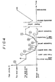
- the graph in Fig. 4 shows the motion of the ram 36.
- the abscissa axis represents the time t, while the ordinate axis represents the ram stroke S of the ram 36.
- the motion of the ram 36 will be described hereinunder with reference to Fig. 4.
- the ram 36 is at the position (origin 0) of the top dead point which is determined by the mechanical mechanism shown in Fig. 2. This position is where a tool is secured to the distal end of the ram 36 or a preparatory operation is conducted. This position is detected by means of a sensor 70 (see Fig. 6) described later.
- the ram 36 moves from the position of the origin 0 to an operation preparing point a which is the top dead point of the operation.
- the operation preparing point a is an extremity point of travel of the ram 3-6 in operation, that is, the top dead point of the press operation.
- the ram 36 starts its pressing motion, that is, it starts the movement from the press start point 1 to the 5high-noise position 3.
- the ram 36 moves at a speed set with the speed A setting 8switch 63.
- the ram 36 moves from the high-noise position 3 to the stop position 5, that is, the bottom dead point.
- the speed of the working operation 4 during this period is set with the speed B setting switch 65, and the ram 36 moves at the set speed B.
- the speed B is set so 6as to be lower than the set speed A. Since the speed at which the ram 36 strikes againt a workpiece is reduced to about 1/3 (variable), the noise is extremely reduced.
- the ram 36 is at rest at the bottom dead point thereof during the interval from the stop position 5 to the stop position 6. This suspension period is set with the timer A setting switch 66. Next, the ram 36 moves upward from the stop position @ to the end position 8.
- the ascending speed during this period is set with the speed C setting switch 67.
- the end position is set in terms of the distance from the bottom dead point of the ram 36 with the S.U.P setting switch 68.
- the speed of movement from the end position 8 to the stop position 9 is the same as the speed. of movement in the interval 2 of movement:
- the stop position 9 is the same as the operation preparing point a from the viewpoint of the position of the ram 36.
- the same motion as the above is repeated from the operation preparing point a.
- Fig. 5 is a functional block diagram showing in detail the controller 4 in Fig. 1.
- a CPU 100 is a 16-bit central processing unit which generally-controls the servo controller 4.
- the CPU 100 receives through an input/outpat unit 101 commands concerning the motion of the ram 36 given from the control and display panel 3.
- the CPU 100 transmits, speed and position commands from the control and display panel 3 to a servo pack 103.
- the servo pack 103 which is arranged to store patterns of motion of the ram 36 in advance, comprises a memory for . storing a program and working data, a central processing circuit (CPU) and an amplifier circuit for supplying electric power to the servomotor.
- the servo pack 103 is . commercially available by a variety of names and its structure and function are known; therefore, detailed description thereof is omitted.
- the servo pack 103 delivers an output to the servomotor 20. Receiving this output, the servomotor 20 rotates.
- the detector 5 As the servomotor 20 starts to rotate, the detector 5 provided on the output shaft of the servomotor 20 outputs the rotation of the servomotor 20 in the form of an electrical digital signal 105.
- the deteqtor 5 is an optical encoder.
- the detector 5 is not necessarily limited thereto, and it is possible to employ any type of detector, for example, an indution- or magnetic-type detector, provided that it is designed to detect rotation.
- a power supply unit 110 is defined by a power transformer or the like for supplying electric power to the servomotor 20.
- a power supply circuit 120 which comprises a transformer, a rectifier circuit and so forth is supplied with an AC power supply to generate direct currents for driving the CPU 100 and a power supply for the output of the CPU 100. In this embodiment, the power supply circuit 120 generates necessary direct currents on the basis of an AC power supply of 100 V.
- the power supply circuit 120 generates DC voltages of 5 V, 12 V and -12 V from an AC voltage of 100 V.
- the AC power supply is input to the power supply circuit 120 through a breaker 122 and a noise filter 121.
- the breaker 122 is employed to cut off an overcurrent or the input power supply when not used.
- the noise filter 121 is an electrical filter for cutting off an electrical noise which may be input through the power supply.
- Fig. 6 schematically shows signals input to. the CPU 100 and the servo pack 110.
- the CPU 110 is supplied as inputs thereof with signals from the "UP" and “DOWN” switches 55 and 56 used to move upward and downward, respectively, the ram in the manual mode.
- An upper-limit switch 70 and a lowerwlimit switch 71 are provided at the upper- and lower-limit positions, respectively, which are determined by the mechanism of the press machine 1.
- the upper-limit switch 70 indicates the above-described origin 0.
- a door interlock limit switch 73, a cover interlock limit switch 74 and a spare limit switch which are interlocked with a door, cover and so forth (not shown) to ensure operator's safety are provided on the door, cover, etc.
- a door interlock limit switch 73, a cover interlock limit switch 74 and a spare limit switch which are interlocked with a door, cover and so forth (not shown) to ensure operator's safety are provided on the door, cover, etc.
- it is necessary to suspend the servomotor 20. Relays for this purpose are provided as being an upper-limit operation stop relay 76 and a lower-limit operation stop relay 77.
- An operation permit display lamp 78 is a display device for indicating that the press machine I can be operated.
- a ram pressure display section 7 is provided, for example, on the upper part of the frame of the press machine 1 for detecting the pressure applied by the ram 3.6.
- the section 7 comprises a strain detecting section a converter for converting a strain into an electric signal and outputing a voltage corresponding to the amount of strain, and a pressure display section. This output value is employed to detect an abnormality in the pressure applied by the ram 36.
- the strain detecting section is attached to the uper surface of the frame 10 (see Fig 2).
- To the servo pack 110 are electrically connected a backward rotation preventing relay 79, a forward rotation preventing relay 80 and an alarm relay. 81.
- Fig. 7 shows a flowchart for executing the servo controller 4.
- the operations of.the servo controller 4 and the press machine 1 will be explained with reference to this flowchart.
- P 1 to P 16 in the figure denote Steps, respectively, in the flowchart.
- the operator turns ON the power supply switch 51 on the control and display panel 3.
- the push-button switch constituting the motor initial switch 53 is pressed to effect initial setting of the servo. controller 4, that is, execute an initial operation,
- the stroke setting switch 60, the speed A setting switch 63, the S.D.P setting switch 64, the speed B setting switch 65, the timer A setting switch 66, the speed C setting switch 67, the S.U.P setting switch 68 and the timer B setting switch 69, which are on the control and display panel 3, are actuated to input data according to the respective functions of these switches shown in Fig. 4.
- the CPU 100 reads command data set through each of the switches 60, 63, 65, 66, 67, 68 and 69 on the control and display panel 3 according to a built-in program.
- the data is transferred to the servo pack 103 through the CPU 100 in Step P2. 'The speed and position data transferred to the servo pack 103 is stored in the memory inside the servo pack 103.
- the servo pack 103 issues a forward rotation start command to the servomotor 20 according to a program previously stored in the servo pack 103 (Step P 3 ).
- the rotation of the servomotor 20 causes the worm 21, the worm wheel 23 and the crankshaft 24 to rotate in the mentioned order.
- the rotation of the crankshaft 24 in the direction of the arrow B causes the crank pin 25 to reciprocate so as to pull the connection 30 in the direction of the arrow B.
- the connection 30 pulls the shaft 31, thus causing the upper and lower arms 32 and 34 to stretch. In consequence, the ram 36 extends downward.
- the ram 36 suspends at the operation preparing point a (Step P 4 ), and after a predetermined suspension period, it starts a press operation (Steps P 5 and P 6 ).
- the speed during this period has already been set through the speed A setting switch 63.
- the output signal 105 from the detector 104 provided on the output shaft of the servomotor 20 is continuously fed back to the servo pack 103.
- the present position of the ram 36 is presumed on the basis of the feedback signal.
- the program in the servo pack 103 causes the speed of rotation of the servomotor 20 to be switched to a speed set through the speed B setting switch 65 in Step P 8 . More specifically, the speed of rotation of the servomotor 20 is reduced to a predetermined proportion with respect to the value set through the speed A setting switch 63. This is a region in which the highest noise is generated in the conventional press machine.
- Step P 9 When the ram 36 is judged to be at the bottom dead point in Step P 9 , it is then judged whether or not a suspension period has already been set through the timer A setting switch 66. If YES, the ram 36 suspends in Step P 10 . When the suspension period has elapsed, the ram 36 then moves upward at a speed set through the speed C setting switch 67 (Step P ll ). The upward movement of the ram 36 is effected by reversing the servomotor 20.
- the entire stroke (as viewed in terms of the mechanism) of the press machine 1 is not used.
- the ascending speed is generally set to a relatively low speed. This is because the workpiece or cuttings may be vacuum-attached to the tool secured to the distal end of the ram 36 and it is therefore necessary to give a sufficient time for the attached workpiece or cuttings to separate therefrom.
- Step P 12 If it is judged in Step P 12 that the ram 36 is at the end position@ the ram 36 moves upward at a speed set through the speed A setting switch 63 (Step P 13 ). It is judged in Step P 14 whether or not the ram 36 has reached the start position. Next, it is judged in Step P 15 whether or not the time set through the timer B setting switch 69 has elapsed. If no time has been set, a subsequent cycle similar to the above is immediately started if the automatic cylce has been set (Step P 16 ). The judgement as to whether not the automatic cycle has been set is made on the basis of the position of the auto/manual switch 54.
- Fig. 8 shows a second embodiment in which a screw driving mechanism is employed for the press machine disclosed in Fig. 2.
- the members which are common with the embodiment shown in Fig. 2 are denoted by the same reference numerals.
- a pulley 202 is keyed to an output shaft 201 of the servomotor 20.
- the pulley 202 is engaged with a timing belt 203.
- the timing belt 203 is, in turn, engaged with a pulley 204.
- a feed screw 205 is keyed to the pulley 204.
- the feed screw 205 is rotatably supported by the frame 10 through a bearing (not shown).
- the feed screw 205 is in thread engagement with a slider 206.
- the slider 206 is slidably provided in a slide guide groove 207 which is defined by a dovetail groove fixed to the frame 10.
- a pin 208 is secured to the slider 206.
- the connection 30 is rotatably fitted on the pin 208.
- the arrangement of the other part of this embodiment is the same as that of the embodiment shown in Fig. 2 and therefore description thereof is omitted.
- the output of the servomotor 20 causes the output shaft 201, the pulley 202, the timing belt 203, the pulley 204 and the feed screw 205-to rotate so as to move the slider 206.
- the movement of the slider 206 causes the pin 208 and the connection 30 to move, thus performing an operation similar to that in the above-described first embodiment.
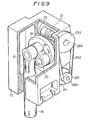
- Fig. 9 shows still another embodiment of the press machine 1 disclosed in Fig. 2.
- a pulley 251 is keyed to an output shaft 250 of the servomotor 20.
- the pulley 251 is engaged with a timing belt 252.
- the timing belt 252 is, in turn, engaged with a pulley 253.
- a worm shaft 254 is keyed to the pulley 253.
- a worm 21 is secured to the worm shaft 254, the worm 21 being formed either integral with the worm shaft 254 or separately therefrom.
- the worm 21 is meshed with a worm wheel 23.
- a crankshaft 24 is coaxially provided on the worm wheel 23.
- a crank pin 25 is secured to the crankshaft 24 at a position which is eccentric with respect to the crankshaft 24.
- One end of a connection 30 is rotatably provided on the crank pin 25.
- a shaft 31 is secured to the other end of the connection 30.
- the upper end of a ram 36 is rotatably provided on the shaft 31.
- the rotational output of the servomotor 20 is transmitted through the output shaft 250, the pulley 251, the timing belt 252, the pulley 253, the worm shaft 254 and the worm 21 to rotate the crankshaft 24.
- the eccentric crank pin 25 revolves around the center of the crankshaft 24. This motion causes the connection 30 to pivot about the crank pin 25.
- the pivotal motion of the connection 30 activates the ram 36 to move up and down.
- the ram 36 in the foregoing embodiments starts from the position of the press start 1, and the speed of the servomotor 20 is stepwisely changed at the high-noise position@.
- the stepwise change of the speed of the servomotor 20 is not necessarily exclusive and the number of revolutions of the servomotor may be changed steplessly along a curve approximated to a quadratic curve. Stepless change of the speed of the servomotor 20 enables the inertia acting on the reduction mechanism and the ram 3 to be changed smoothly as shown in F ig. 10(a), so that no unnatural force acts on the press machine.
- Fig. 10(b) shows an example.in which the speed is changed once during the interval from the press start to the high-noise position so that two different levels of speed are available.
- Fig. 10(c) shows an example in which a vertical vibrating operation is effected during the interval from the stop position 5 to the stop position @ so that the tool secured to the distal end of the ram 36 is smoothly separated from the workpiece.
- Fig. 4 does not show the motion of the ram 36 but schematically shows the motion of the servomotor 20. Accordingly, to make the ram 36 perform the illustrated motion, it may also be possible to directly detect the motion of the ram 36 and control the servomotor 20 on the basis of the detected value. In this case, it is even more preferable to design the system while taking into consideration the converting characteristics of the mechanism for converting a rotational motion into a linear motion. Thus, it is possible to control strictly the speed and position of the ram 36.
- the above-described servo controller 4 electrically realizes the motion of the ram 36; however, as will be clear from the foregoing technical idea of the present invention, the motion of the ram 36 may also be realized by a combination of a mechanical mechanism such as a cam, gear or lever mechanism and a digital servo controller such as that described above. Such an arrangement does not depart from the spirit of the present invention. Further, the above-described digital servo controller may be replaced by an analog controller, provided that it is capable of driving the ram on the basis of the foregoing idea. These... mechanisms may be those which are known in various kinds of industrial machinery such as machine tools and robots. Industrial Applicability
- the method of operating a press machine and servo controller therefor may be applied to plastic working using a press machine, such as shearing work, for example, blanking or piercing, bending, deep drawing and compression forming.
- a press machine such as shearing work, for example, blanking or piercing, bending, deep drawing and compression forming.
- the present invention is applied to working of pins made from metal sheet for semiconductors, the present invention is applicable to working of various parts such as metallic and non-metallic parts for any kind of industrial machinery, office automation equipment and automobiles.
Abstract
Description
- The present invention relates to a method of operating a press machine which enables a reduction in noise generated during an operation of the press machine, and a servo controller therefor. More particularly, the present invention pertains to a method of operating a press machine wherein a servomotor for driving the press machine is program-controlled to reduce the noise generated during an operation of the press machine, and a servo controller therefor.
- Various types of press machine are selected and used in accordance with the kind of plastic working. The press machines may be roughly divided into two types, that is, mechanical presses that employ mechanical force as a drive source for driving the same and hydraulic presses that employ hydraulic pressure such as the pressure of oil or water.
- Mechanical presses have high working speed and high productivity. Hydraulic presses have the following superior features: the pressure application period can be increased; the pressure can be made to last; it is easy to adjust the level of pressure; and it is possible to generate high pressure. As power transmission mechanisms for mechanical presses, mechanisms such as crank-, knuckle joint-, cam-, screw-, rack- and link-type mechanisms are known. Mechanical presses that have no flywheel have screw-, rack-or link-type power transmission mechanisms and many of them are small in size. The storage of energy is small, the stroke is determined in harmony with the resistance of a workpiece, and the bottom dead point is unstable.
- On the other hand, lead frames for ICs are produced by blanking a metallic sheet material. Press machines are used to generate pressure for this blanking. As press machines for this purpose, hydraulic presses are used in the most cases. This is because it is necessary to detect a possible error of the work position with a sensor such as an inspection pin and suspend momentarily the press machine in order to prevent generation of defective products due to, for example, offset of the position of the work inside the blanking die. In other words, hydraulic presses are superior in control characteristics, for example, stop and start, and therefore used for the above-described purpose.
- Hydraulic presses suffer, however, from a considerably unpleasant noise including pumping noise generated in a hydraulic pump, intermittent high-pitched noise generated when the hydraulic pipe for press working expands, solenoid operating noise, etc. In a hydraulic press, even when it is at rest, if the switch for the hydauric pump is ON, electric power is consumed more than that in the case where the press is in an operative state, which is uneconomical....
- Mechanical presses generate a high level of noise including noise generated when the flywheel is rotating, gear transmission noise, noise generated when the clutch is engaged and disengaged, mechanical frictional noise generated due to backlash. Further, in both hydraulic and mechanical presses, when a tool strikes against a workpiece for plastic working, an extremely high impact noise is generated, and also when the cut workpiece is separated from the tool, a noise (also referred to as "stripping noise" in this specification) is generated. Thus, press machines have heretofore been synonymous with main sources of generation of a high level of noise in factories. For this reason, how to reduce the unpleasant noises in both hydraulic and mechanical pressses is the most important subject for people who have been engaged in this industry.
- In general, noise in factories or the like makes people not only feel uncomfortable but also mentally fatigued. As a result, the incidence of workmen's accidents increases, and the working efficiency lowers. In addition, a hearing disorder may be caused. If a person is engaged for a long time in an operation wherein he is exposed to a considerable noise, such as a press working operation, there is a fear that he may suffer from occupational bradyacusia. It is necessary to take some measures from the viewpoint of workmen's health. Under these circumstances, standards have been established by academic societies and laws relevant to the subject on the basis of three factors, that is, the center frequency and the exposure time per day, so that no hearing disorder is caused.
- For example, the Industrial Sanitary Society of Japan established a permissible noise level in 1975. According to this standard, the exposure time per day is limited to 2 hours at 85 phons. To meet this standard, it is conventional practice to surround a press machine with, for example, a noise reducing panel formed in the shape of a box or lower the speed of operation. However, if a press machine is covered with a box-shaped structure, the external size increases and the view of the factory and the operability are extremely impaired. In addition, the factory space is consumed correspondingly.
- A first feature of the present invention resides in a method of operating a press machine designed to apply external force to a part or the whole of the surface of a workpiece to thereby cause plastic deformation therein, comprising an approaching step in which a tool for applying external force to the workpiece is moved at a set speed to approach the workpiece, a working step in which the speed of movement of the tool is reduced so as to be lower than that in the approaching step to thereby cause plastic deformation in the workpiece, and a separating step in which the tool is separated from the workpiece after completion of the working step.
- A second feature of the present invention resides in a servo controller for a press machine having a frame, a servomotor provided on the frame, a power transmission mechanism for transmitting the rotational driving force of the servomotor, and a reciprocating motion conversion mechanism for converting power received from the power transmission mechanism into a reciprocating motion of a ram, the servo controller comprising a control and display panel comprised of a plurality of switches for determining a locus of motion of the ram by controlling the rotation of the servomotor, a servo control unit for controlling the motion of the servomotor, and a central processing unit for giving commands to the servo control unit on the basis of input command signals from the control and display panel.
- If the above-described first feature of the present invention is applied to a conventional hydraulic press, the following problems arise. Since air pressure, oil pressure (air is generally mixed in the oil) or piping acts as a cushion, even if the blanking speed of the ram at the time when a metal sheet is blanked is apparently lowered, blanking starts only after penetration into the workpiece of the tool attached to the distal end of the ram has progressed and pressure for blanking has been stored in the piping. Accordingly, the above-described air pressure, oil pressure and piping undesirably store energy and therefore the speed of the ram at the moment when the workpiece is blanked is increased rather than reduced, which results in generation of a noise. Thus, this application is less effective.
- Since the press machine according to the present invention employs a mechanical mechanism for transmitting pressing pressure, it has less cushioning as in the case of a hydraulic type (air is generally mixed in the liquid) press or an air type press. The present invention enables working to be carried out quietly and gently as if a sheet of iron were cut with tinman's shears. According to an experimental example in one embodiment described later, it was possible with the press of the present invention to reduce the noise to 65 phons or less in an operation of 40 strokes per minute simply by reducing the speed of rotation of the servomotor to about one half of the normal only in one momentary period during which noise was generated, whereas the noise generated in a conventional oil hydraulic press for manufacturing IC lead frames was 85 phons in the same operation, i.e., 40 strokes per minute.
- Further, it was possible to reduce by a large margin the energy consumption as compared with the conventional oil hydraulic press. According to an experimental example in one embodiment described later, the motor of the conventional oil hydraulic press was operated 100% at 2.2 kW. In contrast to this, in the press machine of the present invention having the same capability, a servomotor of 0.5 kW was used 50% in time proportion and the amount of electric energy used was on the average about 1/10 of that in the case of the oil hydraulic press. In a comparison as to the noise level between the method of operating a press machine according to the present invention and a conventional mechanical press also, it was revealed that the noise was reduced by a large margin in substantially the same way as in the case-of the above-described conventional oil hydraulic press. In a size comparison between the present invention and the conventional oil hydraulic press, it was possible to realize a press machine with a size substantially equal to that of the cylinder part of the conventional oil hydraulic press, yet the realized press machine had performance substantially equal to that of the latter. In other words, the press machine according to the present invention can be considerably reduced in size.
- In the case where the ram of a press is designed to move through a certain stroke, the ram of the conventional mechanical press moves through the entire design stroke during working even if it is unnecessary for the ram to do for working. Therefore, when runaway occurs, it is extremely dangerous; therefore, it has heretofore been necessary to take a complete safety measure. Since the servo controller according to the present invention enables the ram to be instantaneously moved at full speed and also suspended, when, for example, an abnormality of a workpiece is detected by means of a detector installed inside the die, the ram can be suspended instantaneously within a short distance.
- Since the travel of the ram is short and it does not move more than is necessary as in the case of the. conventional mechanical press, the press machine of the present invention can be used safely without a fear of the operator's finger entering the space between the tool attached to the distal end of the ram and the workpiece. Since there is no useless movement, the operating efficiency of the press machine is also improved. In addition, it is essential to oil the mechanism part of the mechanical press, and if the operator forgets to oil it, seizing may occur and it may become impossible to use the machine. Thus, the necessity of oiling has heretofore been a troublesome matter. There has been the inconvenience that the whole of the press machine may be sticky with oil.
- In the press machine of the present invention, the mechanism part is formed in a totally-enclosed box and this box is filled with oil. Thus, it is possible to eliminate the troublesome oiling and the fear of seizing due to lack of oil and use the machine stably for a long period of time. Further, the largest merit resides in that the oil filled in the frame incorporating the power transmission mechanism enables a reduction in the mechanical noise. The present invention has the above-described features and aims at attaining the following dubjects.
- It is an object of the present invention to provide a method of operating a press machine which enables a reduction in the noise generated during an operation of the press machine.
- It is another object of the present invention to provide a mechanism for a press machine which enables a reduction in the noise generated during an operation of the press machine.
- It is still another object of the present invention to provide a servo controller which enables a reduction in the noise generated in a series of operations of a press machine.
- It is a further object of the present invention to provide a servo controller for a press machine which is capable of program control so as to optimize a press operation.
- Fig. 1 is a functional block diagram showing an outline of the present invention; Fig. 2 is a partially-cutaway perspective view showing a general view of a
press machine 1 used in the present invention; Fig. 3 shows a control and display panel of the servo controller according to the present invention; Fig. 4 is a graph showing th locus of movement of the ram; Fig. 5 is a functional block diagram showing in detail the servo controller according to the present invention; Fig. 6 shows signals which are input to and output from the servo controller; Fig. 7 is a flowchart showing the operation of the servo controller according to the present invention; Fig. 8 shows another embodiment of the press machine; Fig. 9 shows still another embodiment of the press machine; and Fig. 10 is a graph showing other examples of the locus of movement of the ram. Best Mode for Carying Out the Invention - The present invention will be described hereinunder in more detail with reference to the accompanying drawings.
- Fig. 1 is a functional block diagram showing an outline of the method of operating a press machine and servo controller therefor according to the present invention. A
press machine 1 is provided with a power transmission mechanism for converting the rotational force from aservomotor 20 into a reciprocating motion of a ram, as described later. Adie 2 is provided to carry out a desired machining process such as cutting, blanking or bending. The structure and function of thedie 2 are known and therefore detailed description thereof is omitted. - A control and
display panel 3 is a device for inputting and displaying commands for a series of operations of thepress machine 1 and data for display. Aservo controller 4 controls and operates theservomotor 20 of thepress machine 1 in resposne to commands given by the operator from the control anddisplay panel 3. Theservo controller 4 is also arranged to receive signals, for example, a signal from aram position detector 5 attached to thepress machine 1, input/output signals from a host computer or the like, a detected signal delivered from the inside of thedie 2 andinput signals 6 from various sensors and relays, and process these signals. - Fig. 2 shows the power transmission mechanism of the
press machine 1 according to the present invention, the figure being a perspective view thereof in which theframe 10 is partially cut away. In this embodiment, the technical idea of the present invention is applied to a knuckle joint press. Theframe 10 has a hollow parallelepiped box-shaped configuration. In this embodiment, theframe 10 is produced by machining an aluminum cast metal. This embodiment is a 1-5t press designed to blank lead frames of ICs, the press having a plane of about 200 x 200 mm and a length of about 300 mm. Theframe 10 may be produced by welding steel plate. Theframe 10 has a ram guide bore 13 through which a ram 36 (described later) projects and withdraws, a bore for receiving the output shaft of aservomotor 20, an assembly bore (not shown) for receiving and assembling acrankshaft 24 and the like inside theframe 10. - These receiving and assembly bores are provided with respective 0-rings (not shown) to prevent leakage of gear oil filled inside the
frame 10. The side surface of the bottom of theframe 10 is provided with mountinggrooves 12 which are defined by U-shaped notches. The mountinggrooves 12 are provided to secure theframe 10 to a structure or the like by means of bolts when thepress machine 1 is installed. Anoil drain port 14 is provided in theframe 10 near the bottom thereof for draining the gear oil contained in theframe 10. - The
oil drain port 14 is arranged such that, when the gear oil filling inside theframe 10 is to be drained, a screw screwed in theoil drain port 14 is unscrewed to discharge the gear oil. The upper side of theframe 10 is provided with anoil filling port 15 for filling gear oil. Theoil filling port 15 for filling gear oil into theframe 10 has a structure similar to that of theoil drain port 14. - Gear oil is filled into the space inside the
frame 10 for the purpose of absorbing noise generated from a speed reducing gear mechanism (described later) and atoggle mechanism 40 and of lubricating these mechanisms. It is even more preferable to select a gear oil with the frequency of generated noise being taken into consideration so that the employed gear oil has excellent frequency abating characteristics (in this embodiment a reduction of 8 phons was achieved by the effect of the gear oil alone). Theservomotor 20 is secured to acut portion 11 of theframe 10 by securing means such as bolts. Theservomotor 20 is a motor capable of switching at a high frequency, i.e., 100 to 500 forward and backward revolutions per minute. - One end of a
worm shaft 22 is keyed to the output shaft (not shown) of theservomotor 20. The teeth of aworm 21 are meshed with the teeth of aworm wheel 23. The tooth forms of theworm 21 and theworm wheel 23 are standardized ones. Theworm 21 and theworm wheel 23 form in combination a speed reducing gear mechanism. A disk-shapedcrankshaft 24 is keyed (not shown) to the shaft of theworm wheel 23. - A
crank pin 25 is secuted to thecrankshaft 24 at a position which is a predetermined amount eccentric with respect to the center of thecrankshaft 24. One end of aconnection 30 is rotatably fitted onto thecrank pin 25. The other end of theconnection 30 is rotatably provided on ashaft 31 of atoggle device 40. One end of anupper arm 32 which is defined by two parallel links is pivotally provided on theshaft 31. The other end of theupper arm 32 is pivotally provided on ashaft 33. - Further, the
shaft 31 is rotatably provided with one end of alower arm 34 which is defined by two parallel links. The other end of thelower arm 34 is rotatably provided on ashaft 35. Theshaft 35 is provided in parallel to the above-describedshaft 31. Theshaft 35 is pivotally provided with one end of the ram 36: A tool (not shown) for working is secured to the distal end of theram 36 by known means. - Fig. 3 shows the control and
display panel 3 in detail. Apower supply switch 51 is a switch for ON/OFF controlling the supply of current to theservo controller 4 and theservomotor 20. Astart switch 52 is actuated to start an automatic operation (described later) of theservo controller 4. A motorinitial switch 53 is actuated to cause theservo controller 4 to perform an initial operation. An auto/manual switch 54 is a change-over switch for selecting either an automatic operation or a manufal operation. - An "UP"
switch 55 is a switch for activating theram 36 to move upward in a manual operation. A "DOWN"switch 56 is a switch for activating theram 36 to move downward in a manual operation. Astop switch 57 is a switch for suspending thepress machine 1 when continuously operating under program control (described later). A motor powersupply monitor LED 58 is a monitor which turns ON when thepress machine 1 is OFF-line, that is, when thepress machine 1 is not electrically interlocked with another machine, and a servomotorpower supply unit 110 is ON. A press auto-operation permit LED 59 is a monitor arranged such that the LED turns ON when thepress machine 1 is OFF-line and in a start permit state. - The functions of switches disposed on the upper part of the control and
display panel 3 will next be explained. These switches are used to set a motion of theram 36. Thestroke setting switch 60 is actuated to set a range within which theram 36 is movable, that is, a length of movement of theram 36. Theswitch 60 has adisplay section 62 for numerically displaying a set distance, that is, a length. Anegative stepping switch 61a for decrement is provided at the upper side of thedisplay section 62 in correspondence with one digit displayed therein. Thenegative stepping switch 61a is arranged such that, every time it is pressed, the corresponding numeral displayed in thedisplay section 62 is decremented by a minimum unit. - A
positive stepping switch 61b which is provided at the lower side of thedisplay section 62 is arranged such that, every time it is pressed, the corresponding displayed numeral is incremented in reverse to the above. In this embodiment, thestroke setting switch 60 enables a stroke to be set in units of 1 mm (minimum step) within a range of from 1 to 29 mm. From the viewpoint of the mechanism, theram 36 is capable of moving through 80 mm; however, it suffices to use only part of it as a stroke in a press operation. Accordingly; there is no waste in the press operation. It should be noted that numerals which are specified in this embodiment are only references for helping understanding of this embodiment and in no way restrict the present invention. - All the
switches stroke setting switch 60 and are different from each other only in terms of steps and units of data which are to be set thereby. The speedA setting switch 63 is used to set an operation speed of theram 36 of the press. The speed A is a set number of revolutions of theservomotor 20 for controlling the same. In this embodiment, the speed A can be set in step units of 10 rpm within a range of from 10 rpm to 90 rpm. The slow- down start point (S.D.P) settingswitch 64 is used to set a position at which theram 36 reduces its descending speed before performing a working operation, which is one of the significant features of the present invention. This set value represents a distance from the bottom dead point of theram 36. In this embodiment, the set value can be set in a step of 0.5 mm within a range of from 0 mm to 9.5 mm. - If the
S.D.P setting switch 64 is set to 0 mm, theram 36 moves to the bottom dead point without slowing down. The speedB setting switch 65 is used to set a descending speed of theram 36 from a position set with theS.D.P setting switch 64. The speed B is set in terms of percentage with respect to a value set through the speedA setting switch 63. In this embodiment, the speed B is set in a step of 10% within a range of from 10% to 100%. The timerB setting switch 66 is a switch used to set a suspension period during which theram 36 is at rest at the bottom dead point thereof. - In this embodiment, the suspension period can be set in a step of 0.1 sec within a range of from 0 sec to 9.9 sec. The speed
C setting switch 67 is used to set an ascending speed of theram 36. In this embodiment, the speed C can be set in a step of 10% within a range of from 10 to 100% with respect to a set value for the speed A. The slow-up start point (S.U.P) settingswitch 68 is used to set a distance from the bottom dead point of theram 36. Up to this set point, theram 36 moves upward at a speed set with the speedC setting switch 67. - The timer
B setting switch 69 is a switch used to set a suspension period during which the ram 39 is at rest at the top dead point thereof. In this embodiment, the suspension period can be set in a step of 0.1 sec within a range of from 0 sec to 9.9 sec. - The graph in Fig. 4 shows the motion of the
ram 36. The abscissa axis represents the time t, while the ordinate axis represents the ram stroke S of theram 36. The motion of theram 36 will be described hereinunder with reference to Fig. 4. Initially, theram 36 is at the position (origin 0) of the top dead point which is determined by the mechanical mechanism shown in Fig. 2. This position is where a tool is secured to the distal end of theram 36 or a preparatory operation is conducted. This position is detected by means of a sensor 70 (see Fig. 6) described later. - When the
press machine 1 is activated, theram 36 moves from the position of theorigin 0 to an operation preparing point a which is the top dead point of the operation. The operation preparing point a is an extremity point of travel of the ram 3-6 in operation, that is, the top dead point of the press operation. If the above-describedstart switch 52 is pressed when theram 36 is at the operation preparing ⑤point a, theram 36 starts its pressing motion, that is, it starts the movement from thepress start point ① to the ⑤high-noise position ③. During theinterval ② of movement from thepress start point ① to the high-noise position theram 36 moves at a speed set with the speedA setting ⑧switch 63. Next, theram 36 moves from the high-noise position ③ to thestop position ⑤, that is, the bottom dead point. - The speed of the working
operation 4 during this period is set with the speedB setting switch 65, and theram 36 moves at the set speed B. In general, the speed B is set so ⑥as to be lower than the set speed A. Since the speed at which theram 36 strikes againt a workpiece is reduced to about 1/3 (variable), the noise is extremely reduced. Theram 36 is at rest at the bottom dead point thereof during the interval from thestop position ⑤ to thestop position ⑥. This suspension period is set with the timerA setting switch 66. Next, theram 36 moves upward from the stop position @ to the end position ⑧. - The ascending speed during this period is set with the speed
C setting switch 67. The end position is set in terms of the distance from the bottom dead point of theram 36 with theS.U.P setting switch 68. The speed of movement from the end position ⑧ to thestop position ⑨ is the same as the speed. of movement in theinterval ② of movement: Thestop position ⑨ is the same as the operation preparing point a from the viewpoint of the position of theram 36. The same motion as the above is repeated from the operation preparing point a. Upon completion of all of the operation, thepress machine 1 returns to the origin O determined by the mechanism of thepress machine 1.Controller 4 - Fig. 5 is a functional block diagram showing in detail the
controller 4 in Fig. 1. ACPU 100 is a 16-bit central processing unit which generally-controls theservo controller 4. TheCPU 100 receives through an input/outpat unit 101 commands concerning the motion of theram 36 given from the control anddisplay panel 3. TheCPU 100 transmits, speed and position commands from the control anddisplay panel 3 to aservo pack 103. - The
servo pack 103, which is arranged to store patterns of motion of theram 36 in advance, comprises a memory for . storing a program and working data, a central processing circuit (CPU) and an amplifier circuit for supplying electric power to the servomotor. Theservo pack 103 is . commercially available by a variety of names and its structure and function are known; therefore, detailed description thereof is omitted. In response to a command, theservo pack 103 delivers an output to theservomotor 20. Receiving this output, theservomotor 20 rotates. - As the
servomotor 20 starts to rotate, thedetector 5 provided on the output shaft of theservomotor 20 outputs the rotation of theservomotor 20 in the form of an electricaldigital signal 105. In this embodiment, thedeteqtor 5 is an optical encoder. However, thedetector 5 is not necessarily limited thereto, and it is possible to employ any type of detector, for example, an indution- or magnetic-type detector, provided that it is designed to detect rotation. Apower supply unit 110 is defined by a power transformer or the like for supplying electric power to theservomotor 20. Apower supply circuit 120 which comprises a transformer, a rectifier circuit and so forth is supplied with an AC power supply to generate direct currents for driving theCPU 100 and a power supply for the output of theCPU 100. In this embodiment, thepower supply circuit 120 generates necessary direct currents on the basis of an AC power supply of 100 V. - In this embodiment, the
power supply circuit 120 generates DC voltages of 5 V, 12 V and -12 V from an AC voltage of 100 V. The AC power supply is input to thepower supply circuit 120 through abreaker 122 and anoise filter 121. Thebreaker 122 is employed to cut off an overcurrent or the input power supply when not used. Thenoise filter 121 is an electrical filter for cutting off an electrical noise which may be input through the power supply. These various elements have heretofore been known. - Fig. 6 schematically shows signals input to. the
CPU 100 and theservo pack 110. TheCPU 110 is supplied as inputs thereof with signals from the "UP" and "DOWN" switches 55 and 56 used to move upward and downward, respectively, the ram in the manual mode. An upper-limit switch 70 and alowerwlimit switch 71 are provided at the upper- and lower-limit positions, respectively, which are determined by the mechanism of thepress machine 1. The upper-limit switch 70 indicates the above-describedorigin 0. - In addition, a door interlock limit switch 73, a cover
interlock limit switch 74 and a spare limit switch which are interlocked with a door, cover and so forth (not shown) to ensure operator's safety are provided on the door, cover, etc. Further, in order to suspend theram 36 at the above-described upper- and lower-limit positions determined by the mechanism, it is necessary to suspend theservomotor 20. Relays for this purpose are provided as being an upper-limitoperation stop relay 76 and a lower-limitoperation stop relay 77. An operationpermit display lamp 78 is a display device for indicating that the press machine I can be operated. - A ram
pressure display section 7 is provided, for example, on the upper part of the frame of thepress machine 1 for detecting the pressure applied by the ram 3.6. Thesection 7 comprises a strain detecting section a converter for converting a strain into an electric signal and outputing a voltage corresponding to the amount of strain, and a pressure display section. This output value is employed to detect an abnormality in the pressure applied by theram 36. The strain detecting section is attached to the uper surface of the frame 10 (see Fig 2). To theservo pack 110 are electrically connected a backwardrotation preventing relay 79, a forwardrotation preventing relay 80 and an alarm relay. 81. - The operations of the
press machine 1 and theservo controller 4 will be described hereinunder. Fig. 7 shows a flowchart for executing theservo controller 4. The operations of.theservo controller 4 and thepress machine 1 will be explained with reference to this flowchart. It should be noted that P1 to P16 in the figure denote Steps, respectively, in the flowchart. The operator turns ON thepower supply switch 51 on the control anddisplay panel 3. Then, the push-button switch constituting the motorinitial switch 53 is pressed to effect initial setting of the servo.controller 4, that is, execute an initial operation, - The
stroke setting switch 60, the speedA setting switch 63, theS.D.P setting switch 64, the speedB setting switch 65, the timerA setting switch 66, the speedC setting switch 67, theS.U.P setting switch 68 and the timerB setting switch 69, which are on the control anddisplay panel 3, are actuated to input data according to the respective functions of these switches shown in Fig. 4. - As the button of the
start switch 52 is pressed, theCPU 100 reads command data set through each of theswitches display panel 3 according to a built-in program. The data is transferred to theservo pack 103 through theCPU 100 in Step P2. 'The speed and position data transferred to theservo pack 103 is stored in the memory inside theservo pack 103. - The
servo pack 103 issues a forward rotation start command to theservomotor 20 according to a program previously stored in the servo pack 103 (Step P3). The rotation of theservomotor 20 causes theworm 21, theworm wheel 23 and thecrankshaft 24 to rotate in the mentioned order. The rotation of thecrankshaft 24 in the direction of the arrow B causes thecrank pin 25 to reciprocate so as to pull theconnection 30 in the direction of the arrow B. Theconnection 30 pulls theshaft 31, thus causing the upper andlower arms ram 36 extends downward. - The
ram 36 suspends at the operation preparing point a (Step P4), and after a predetermined suspension period, it starts a press operation (Steps P5 and P6). The speed during this period has already been set through the speedA setting switch 63. In the meantime, theoutput signal 105 from the detector 104 provided on the output shaft of theservomotor 20 is continuously fed back to theservo pack 103. The present position of theram 36 is presumed on the basis of the feedback signal. - When it is detected by counting the feedback signal that the
ram 36 has reached the high-noise position ③ (Step P7), the program in theservo pack 103 causes the speed of rotation of theservomotor 20 to be switched to a speed set through the speed B setting switch 65 in Step P8. More specifically, the speed of rotation of theservomotor 20 is reduced to a predetermined proportion with respect to the value set through the speedA setting switch 63. This is a region in which the highest noise is generated in the conventional press machine. - This is because the tool attached to the distal end of the ram applies an impact to the workpiece and at this moment the workpiece, the tool, etc. cause vibrations. Assuming that the stroke determined by the mechanism is S, the value set through the speed A setting switch is V, the value set through the
stroke setting switch 60 is S1, the value set through theS.D.P setting switch 64 is S2 and the value set through the speedB setting switch 65 is V1, then the working speed of the conventional press machine is t=S/V, whereas that of the present invention is t2=(S1-S2) /V+S2/V1. - Let us make a comparison between °a case where the amounts set through the above-described setting switches 60, 63, 64, 65, 66, 67, 68 and 69 are assumed to be 13 mm (S1)' 60 rpm. (V), 1.0 mm (S2), 30% (V1). 00 sec, 50%, 1:5 mm and 0.1 sec, respectively, and a case where a working operation is conducted with a conventional oil hydraulic press machine at a uniform speed over the entire stroke, i.e., 80 mm (S). If the other conditions are the same, the total working time is reduced to about 1/5 of that in the case of the prior art. Accordingly, the noise is reduced by a large margin and the working efficiency is improved.
- When the
ram 36 is judged to be at the bottom dead point in Step P9, it is then judged whether or not a suspension period has already been set through the timerA setting switch 66. If YES, theram 36 suspends in Step P10. When the suspension period has elapsed, theram 36 then moves upward at a speed set through the speed C setting switch 67 (Step Pll). The upward movement of theram 36 is effected by reversing theservomotor 20. - More specifically, since the
servomotor 20 is reversed as described above, the entire stroke (as viewed in terms of the mechanism) of thepress machine 1 is not used. However, it should be noted that the use of the entire stroke as viewed in the mechanism does not depart from the present invention. The ascending speed is generally set to a relatively low speed. This is because the workpiece or cuttings may be vacuum-attached to the tool secured to the distal end of theram 36 and it is therefore necessary to give a sufficient time for the attached workpiece or cuttings to separate therefrom. - If it is judged in Step P12 that the
ram 36 is at the end position@ theram 36 moves upward at a speed set through the speed A setting switch 63 (Step P13). It is judged in Step P14 whether or not theram 36 has reached the start position. Next, it is judged in Step P15 whether or not the time set through the timerB setting switch 69 has elapsed. If no time has been set, a subsequent cycle similar to the above is immediately started if the automatic cylce has been set (Step P16). The judgement as to whether not the automatic cycle has been set is made on the basis of the position of the auto/manual switch 54. - Fig. 8 shows a second embodiment in which a screw driving mechanism is employed for the press machine disclosed in Fig. 2. The members which are common with the embodiment shown in Fig. 2 are denoted by the same reference numerals. A
pulley 202 is keyed to anoutput shaft 201 of theservomotor 20. Thepulley 202 is engaged with atiming belt 203. Thetiming belt 203 is, in turn, engaged with apulley 204. Afeed screw 205 is keyed to thepulley 204. - The
feed screw 205 is rotatably supported by theframe 10 through a bearing (not shown). Thefeed screw 205 is in thread engagement with aslider 206. Theslider 206 is slidably provided in aslide guide groove 207 which is defined by a dovetail groove fixed to theframe 10. Apin 208 is secured to theslider 206. Theconnection 30 is rotatably fitted on thepin 208. The arrangement of the other part of this embodiment is the same as that of the embodiment shown in Fig. 2 and therefore description thereof is omitted. - The output of the
servomotor 20 causes theoutput shaft 201, thepulley 202, thetiming belt 203, thepulley 204 and the feed screw 205-to rotate so as to move theslider 206. The movement of theslider 206 causes thepin 208 and theconnection 30 to move, thus performing an operation similar to that in the above-described first embodiment. - Fig. 9 shows still another embodiment of the
press machine 1 disclosed in Fig. 2. Apulley 251 is keyed to anoutput shaft 250 of theservomotor 20. Thepulley 251 is engaged with atiming belt 252. Thetiming belt 252 is, in turn, engaged with apulley 253. Aworm shaft 254 is keyed to thepulley 253. Aworm 21 is secured to theworm shaft 254, theworm 21 being formed either integral with theworm shaft 254 or separately therefrom. - The
worm 21 is meshed with aworm wheel 23. Acrankshaft 24 is coaxially provided on theworm wheel 23. Acrank pin 25 is secured to thecrankshaft 24 at a position which is eccentric with respect to thecrankshaft 24. One end of aconnection 30 is rotatably provided on thecrank pin 25. Ashaft 31 is secured to the other end of theconnection 30. The upper end of aram 36 is rotatably provided on theshaft 31. After all, the crankshaft, thecrank pin 25, theconnection 30, theshaft 31 and theram 36 form in combination a crank mechanism for converting a rotational motion into a linear motion. The rotational output of theservomotor 20 is transmitted through theoutput shaft 250, thepulley 251, thetiming belt 252, thepulley 253, theworm shaft 254 and theworm 21 to rotate thecrankshaft 24. As thecrankshaft 24 rotates, theeccentric crank pin 25 revolves around the center of thecrankshaft 24. This motion causes theconnection 30 to pivot about thecrank pin 25. The pivotal motion of theconnection 30 activates theram 36 to move up and down. - The
ram 36 in the foregoing embodiments starts from the position of thepress start ①, and the speed of theservomotor 20 is stepwisely changed at the high-noise position@. However, the stepwise change of the speed of theservomotor 20 is not necessarily exclusive and the number of revolutions of the servomotor may be changed steplessly along a curve approximated to a quadratic curve. Stepless change of the speed of theservomotor 20 enables the inertia acting on the reduction mechanism and theram 3 to be changed smoothly as shown in Fig. 10(a), so that no unnatural force acts on the press machine. - Fig. 10(b) shows an example.in which the speed is changed once during the interval from the press start to the high-noise position so that two different levels of speed are available. Fig. 10(c) shows an example in which a vertical vibrating operation is effected during the interval from the
stop position ⑤ to the stop position @ so that the tool secured to the distal end of theram 36 is smoothly separated from the workpiece. - Strictly speaking, Fig. 4 does not show the motion of the
ram 36 but schematically shows the motion of theservomotor 20. Accordingly, to make theram 36 perform the illustrated motion, it may also be possible to directly detect the motion of theram 36 and control theservomotor 20 on the basis of the detected value. In this case, it is even more preferable to design the system while taking into consideration the converting characteristics of the mechanism for converting a rotational motion into a linear motion. Thus, it is possible to control strictly the speed and position of theram 36. - The above-described
servo controller 4 electrically realizes the motion of theram 36; however, as will be clear from the foregoing technical idea of the present invention, the motion of theram 36 may also be realized by a combination of a mechanical mechanism such as a cam, gear or lever mechanism and a digital servo controller such as that described above. Such an arrangement does not depart from the spirit of the present invention. Further, the above-described digital servo controller may be replaced by an analog controller, provided that it is capable of driving the ram on the basis of the foregoing idea. These... mechanisms may be those which are known in various kinds of industrial machinery such as machine tools and robots. Industrial Applicability - As described above, the method of operating a press machine and servo controller therefor according to the present invention may be applied to plastic working using a press machine, such as shearing work, for example, blanking or piercing, bending, deep drawing and compression forming. Although in the-foregoing embodiments the present invention is applied to working of pins made from metal sheet for semiconductors, the present invention is applicable to working of various parts such as metallic and non-metallic parts for any kind of industrial machinery, office automation equipment and automobiles.
Claims (9)
Priority Applications (1)
| Application Number | Priority Date | Filing Date | Title |
|---|---|---|---|
| EP92118455A EP0536804B1 (en) | 1986-12-29 | 1987-12-25 | Method of operating a press |
Applications Claiming Priority (2)
| Application Number | Priority Date | Filing Date | Title |
|---|---|---|---|
| JP310994/86 | 1986-12-29 | ||
| JP31099486 | 1986-12-29 |
Related Child Applications (1)
| Application Number | Title | Priority Date | Filing Date |
|---|---|---|---|
| EP92118455A Division-Into EP0536804B1 (en) | 1986-12-29 | 1987-12-25 | Method of operating a press |
Publications (3)
| Publication Number | Publication Date |
|---|---|
| EP0302936A1 true EP0302936A1 (en) | 1989-02-15 |
| EP0302936A4 EP0302936A4 (en) | 1990-12-12 |
| EP0302936B1 EP0302936B1 (en) | 1993-12-01 |
Family
ID=18011853
Family Applications (2)
| Application Number | Title | Priority Date | Filing Date |
|---|---|---|---|
| EP92118455A Revoked EP0536804B1 (en) | 1986-12-29 | 1987-12-25 | Method of operating a press |
| EP88900584A Expired - Lifetime EP0302936B1 (en) | 1986-12-29 | 1987-12-25 | Servo controller for a press machine |
Family Applications Before (1)
| Application Number | Title | Priority Date | Filing Date |
|---|---|---|---|
| EP92118455A Revoked EP0536804B1 (en) | 1986-12-29 | 1987-12-25 | Method of operating a press |
Country Status (5)
| Country | Link |
|---|---|
| US (2) | US5069060A (en) |
| EP (2) | EP0536804B1 (en) |
| KR (1) | KR920000023B1 (en) |
| DE (2) | DE3751877T2 (en) |
| WO (1) | WO1988004990A1 (en) |
Cited By (4)
| Publication number | Priority date | Publication date | Assignee | Title |
|---|---|---|---|---|
| EP0466379A2 (en) * | 1990-07-02 | 1992-01-15 | Hokkai Can Co., Ltd. | Apparatus for lifting and lowering seaming head in can end seaming machine |
| EP0616882A1 (en) * | 1993-03-23 | 1994-09-28 | Leinhaas Umformtechnik GmbH | Method for hydraulically controlling a link-type press or a toggle press and link-type press or toggle press with a control system adapted for carrying out the method |
| EP1281508A2 (en) * | 2001-08-02 | 2003-02-05 | Komage-Gellner Maschinenfabrik KG | Press and method for operating a press |
| CN103402666A (en) * | 2010-10-21 | 2013-11-20 | 许勒压力机有限责任公司 | Drawing press with dynamically optimized blank holding |
Families Citing this family (33)
| Publication number | Priority date | Publication date | Assignee | Title |
|---|---|---|---|---|
| JP3169247B2 (en) * | 1991-12-03 | 2001-05-21 | 株式会社石井工作研究所 | Pressing force automatic control method and device for press machine |
| IT226476Z2 (en) * | 1992-04-14 | 1997-06-24 | Whirlpool Italia | DEVICE SUITABLE FOR CHECKING AND COMMANDING THE OPERATION OF A WASHING MACHINE OR SIMILAR OR OTHER HOME APPLIANCES SUCH AS OVEN HOB OR SIMILAR WITH A SERVO-ASSISTED KNOB |
| US5483874A (en) * | 1994-03-18 | 1996-01-16 | Janome Sewing Machine Co., Ltd. | Electropressing apparatus with computer programmable control |
| JP2705591B2 (en) * | 1994-10-04 | 1998-01-28 | 村田機械株式会社 | Punch drive controller |
| US5697146A (en) * | 1994-12-28 | 1997-12-16 | Yazaki Corporation | Apparatus for crimping terminal to electrical wire |
| US5669257A (en) * | 1994-12-28 | 1997-09-23 | Yazaki Corporation | Method of crimping terminal and apparatus for the same |
| US5727409A (en) * | 1994-12-28 | 1998-03-17 | Yazaki Corporation | Method of controlling a terminal crimping apparatus |
| JP3551541B2 (en) * | 1995-04-12 | 2004-08-11 | 村田機械株式会社 | Press machine drive |
| US5666838A (en) * | 1995-06-05 | 1997-09-16 | Efco, Incorporated | Forging press for use with automated multi-station transport system |
| JP3025421B2 (en) * | 1995-06-14 | 2000-03-27 | 三菱電機株式会社 | Abnormality detection device for control system |
| JP3171124B2 (en) * | 1996-09-05 | 2001-05-28 | 村田機械株式会社 | Punch press drive |
| IT1289725B1 (en) * | 1996-12-10 | 1998-10-16 | Fomb Officine Meccaniche Bongi | DRUM PRESSES, IN PARTICULAR FOR CLAY PRODUCTS, PERFECTED |
| US6240626B1 (en) * | 1997-02-21 | 2001-06-05 | Novopress Gmbh Pressen Und Presswerkzauge & Co. Kg | Pressing device |
| SE512677C2 (en) * | 1998-09-08 | 2000-05-02 | Rune Nilsson | Methods and apparatus for feeding elongated objects |
| DE19947689C2 (en) * | 1999-09-24 | 2002-02-07 | Sms Demag Ag | Press with eccentric crank drive for upper punch unit and operating method |
| CN1184027C (en) * | 1999-11-05 | 2005-01-12 | 株式会社阿玛达 | Press brake and method of controlling bidirectional fluid pump of hydraulic cylinder of press brake |
| TW514568B (en) * | 2000-01-17 | 2002-12-21 | Amada Co Ltd | Ram speed monitoring method in a press brake and the press brake using the ram speed monitoring method, and ram position control method and ram position controlling device using the ram position control method |
| TW473428B (en) | 2000-03-31 | 2002-01-21 | Nat Science Council | A system of multi-purpose variable-speed servo-controlled crank-slider presses |
| US6487885B2 (en) * | 2000-10-30 | 2002-12-03 | Komax Holding Ag | Method and apparatus for producing a crimped connection |
| US6940252B2 (en) * | 2001-01-31 | 2005-09-06 | Canon Kabushiki Kaisha | DC motor control method and apparatus |
| SE519761C2 (en) * | 2001-09-27 | 2003-04-08 | Brain Invest Internat Ab | Perforator |
| KR100509376B1 (en) * | 2001-12-21 | 2005-08-22 | 아이다엔지니어링가부시끼가이샤 | Press machine |
| JP4296072B2 (en) * | 2003-10-21 | 2009-07-15 | 蛇の目ミシン工業株式会社 | Electric press |
| DE102004009256B4 (en) * | 2004-02-26 | 2008-04-03 | Schuler Pressen Gmbh & Co. Kg | Mechanical multi-servo press |
| JP5060742B2 (en) * | 2005-06-28 | 2012-10-31 | 株式会社アマダ | Press machine, crank press machine, and vibration processing method |
| JP4083767B2 (en) * | 2005-12-22 | 2008-04-30 | ファナック株式会社 | Numerical control device to control servo motor |
| EP1981701B1 (en) * | 2006-02-06 | 2015-12-09 | Abb Research Ltd. | Mechanical press drive system |
| DE102007026727B4 (en) * | 2006-06-08 | 2014-12-31 | Müller Weingarten AG | Drive system of a forming press |
| NL2000449C2 (en) * | 2007-01-22 | 2008-07-23 | Fico Bv | Method and device for mechanically processing semiconductor products in a press. |
| JP2009090318A (en) * | 2007-10-09 | 2009-04-30 | Nisshin Steel Co Ltd | Method of deep-drawing square tube made of metal plate |
| WO2011055585A1 (en) * | 2009-11-03 | 2011-05-12 | 新東工業株式会社 | Electric cylinder control method and electric cylinder control system |
| JP5205417B2 (en) * | 2010-05-27 | 2013-06-05 | コマツ産機株式会社 | Press machine and control method of press machine |
| JP5802230B2 (en) * | 2013-03-14 | 2015-10-28 | アイダエンジニアリング株式会社 | Drawing method and servo press system |
Citations (8)
| Publication number | Priority date | Publication date | Assignee | Title |
|---|---|---|---|---|
| DE518347C (en) * | 1929-07-21 | 1931-02-14 | Theodor Kraegeloh & Co | Toggle press |
| US2269758A (en) * | 1938-10-12 | 1942-01-13 | Noronha Rubber Products Corp D | Mechanical press |
| US3046875A (en) * | 1958-09-19 | 1962-07-31 | Bobst And Son S A | Presses working sheet material |
| DE2608757A1 (en) * | 1975-03-04 | 1976-09-16 | Sato Fumio | METHOD AND DEVICE FOR DAMPING VIBRATION AND WORK NOISE OF A CRANK PRESS |
| DE2631441A1 (en) * | 1975-07-15 | 1977-01-27 | Hermsdorf Keramik Veb | Isostatic ceramic slender insulator pressing mould - has rubber walls connected to vibrating solenoids for easy removal of mouldings |
| US4095522A (en) * | 1977-07-01 | 1978-06-20 | Verson Allsteel Press Company | Sound abatement device for mechanical presses |
| FR2382038A1 (en) * | 1977-02-23 | 1978-09-22 | Dietrich & Cie De | Mechanical press fully automatic control system - has multi-sequenced operation adaptable to various shapes and sizes of workpieces |
| US4297870A (en) * | 1978-03-20 | 1981-11-03 | Canron Corp. | Hydraulic press with integral knockout and stroke control |
Family Cites Families (20)
| Publication number | Priority date | Publication date | Assignee | Title |
|---|---|---|---|---|
| US3602947A (en) * | 1969-02-05 | 1971-09-07 | Morgan Industries Inc | Automatic control system |
| US3827328A (en) * | 1972-12-26 | 1974-08-06 | Greenerd Press & Machine Co In | Control system for hydraulic presses |
| CH572378A5 (en) * | 1973-11-19 | 1976-02-13 | Oerlikon Buehrle Ag | |
| US3939314A (en) * | 1974-06-24 | 1976-02-17 | The Positive Safety Manufacturing Company | Safety device for power-operated presses and the like |
| US4063627A (en) * | 1976-11-10 | 1977-12-20 | Textron, Inc. | Pneumatic control system for a press |
| JPS5610479Y2 (en) * | 1979-03-10 | 1981-03-09 | ||
| US4280182A (en) * | 1979-05-14 | 1981-07-21 | John Mickowski | Microcomputer control system |
| US4350091A (en) * | 1980-01-15 | 1982-09-21 | J. E. Myles, Inc. | Crank press with hydraulic transmission |
| US4348943A (en) * | 1980-04-28 | 1982-09-14 | Hydroacoustics Inc. | Hydraulic press apparatus |
| JPS5966932A (en) * | 1982-10-06 | 1984-04-16 | Senba Tekko Kk | Method and device for trimming sheet formed goods in press forming machine |
| JPS6052095A (en) * | 1983-08-31 | 1985-03-23 | 富士通株式会社 | Multilayer circuit board and method of producing same |
| JPS61189821A (en) * | 1985-02-15 | 1986-08-23 | Nippon Kokan Kk <Nkk> | Driving control device for press brake |
| JPS61202727A (en) * | 1985-03-06 | 1986-09-08 | Mitsubishi Electric Corp | Bending device |
| US4743900A (en) * | 1985-08-12 | 1988-05-10 | Siemens Aktiengesellschaft | Device for releasing control signals for a machine tool |
| JPH0724955B2 (en) * | 1986-02-07 | 1995-03-22 | 株式会社アマダ | Press machine controller |
| JPS62183919A (en) * | 1986-02-07 | 1987-08-12 | Amada Co Ltd | Stroke control method for plate working machine |
| CA1335638C (en) * | 1987-12-04 | 1995-05-23 | Kinshirou Naito | Method and device for controlling the stroke of a press |
| JPH0616958B2 (en) * | 1988-11-25 | 1994-03-09 | 橋本フォーミング工業株式会社 | Work processing device |
| US4929276A (en) * | 1989-05-22 | 1990-05-29 | Murata Wiedemann, Inc. | Multitool punch holder |
| JP2574820Y2 (en) * | 1992-12-03 | 1998-06-18 | アイワ株式会社 | Stopper mechanism for disk devices, etc. |
-
1987
- 1987-12-25 EP EP92118455A patent/EP0536804B1/en not_active Revoked
- 1987-12-25 DE DE3751877T patent/DE3751877T2/en not_active Revoked
- 1987-12-25 KR KR1019880700729A patent/KR920000023B1/en not_active IP Right Cessation
- 1987-12-25 DE DE88900584T patent/DE3788349T2/en not_active Expired - Lifetime
- 1987-12-25 WO PCT/JP1987/001032 patent/WO1988004990A1/en active IP Right Grant
- 1987-12-25 EP EP88900584A patent/EP0302936B1/en not_active Expired - Lifetime
-
1990
- 1990-06-25 US US07/542,556 patent/US5069060A/en not_active Expired - Lifetime
- 1990-12-14 US US07/627,459 patent/US5079489A/en not_active Expired - Lifetime
Patent Citations (8)
| Publication number | Priority date | Publication date | Assignee | Title |
|---|---|---|---|---|
| DE518347C (en) * | 1929-07-21 | 1931-02-14 | Theodor Kraegeloh & Co | Toggle press |
| US2269758A (en) * | 1938-10-12 | 1942-01-13 | Noronha Rubber Products Corp D | Mechanical press |
| US3046875A (en) * | 1958-09-19 | 1962-07-31 | Bobst And Son S A | Presses working sheet material |
| DE2608757A1 (en) * | 1975-03-04 | 1976-09-16 | Sato Fumio | METHOD AND DEVICE FOR DAMPING VIBRATION AND WORK NOISE OF A CRANK PRESS |
| DE2631441A1 (en) * | 1975-07-15 | 1977-01-27 | Hermsdorf Keramik Veb | Isostatic ceramic slender insulator pressing mould - has rubber walls connected to vibrating solenoids for easy removal of mouldings |
| FR2382038A1 (en) * | 1977-02-23 | 1978-09-22 | Dietrich & Cie De | Mechanical press fully automatic control system - has multi-sequenced operation adaptable to various shapes and sizes of workpieces |
| US4095522A (en) * | 1977-07-01 | 1978-06-20 | Verson Allsteel Press Company | Sound abatement device for mechanical presses |
| US4297870A (en) * | 1978-03-20 | 1981-11-03 | Canron Corp. | Hydraulic press with integral knockout and stroke control |
Non-Patent Citations (1)
| Title |
|---|
| See also references of WO8804990A1 * |
Cited By (8)
| Publication number | Priority date | Publication date | Assignee | Title |
|---|---|---|---|---|
| EP0466379A2 (en) * | 1990-07-02 | 1992-01-15 | Hokkai Can Co., Ltd. | Apparatus for lifting and lowering seaming head in can end seaming machine |
| EP0466379A3 (en) * | 1990-07-02 | 1992-04-08 | Hokkai Can Co., Ltd. | Apparatus for lifting and lowering seaming head in can end seaming machine |
| US5139382A (en) * | 1990-07-02 | 1992-08-18 | Hokkai Can Co., Ltd. | Apparatus for lifting and lowering seaming head in can end seaming machine |
| EP0616882A1 (en) * | 1993-03-23 | 1994-09-28 | Leinhaas Umformtechnik GmbH | Method for hydraulically controlling a link-type press or a toggle press and link-type press or toggle press with a control system adapted for carrying out the method |
| EP1281508A2 (en) * | 2001-08-02 | 2003-02-05 | Komage-Gellner Maschinenfabrik KG | Press and method for operating a press |
| EP1281508A3 (en) * | 2001-08-02 | 2003-03-19 | Komage-Gellner Maschinenfabrik KG | Press and method for operating a press |
| CN103402666A (en) * | 2010-10-21 | 2013-11-20 | 许勒压力机有限责任公司 | Drawing press with dynamically optimized blank holding |
| CN103402666B (en) * | 2010-10-21 | 2016-01-20 | 许勒压力机有限责任公司 | With the drawing press of the plate fixed part of Dynamics Optimization |
Also Published As
| Publication number | Publication date |
|---|---|
| DE3751877D1 (en) | 1996-09-26 |
| WO1988004990A1 (en) | 1988-07-14 |
| US5079489A (en) | 1992-01-07 |
| KR920000023B1 (en) | 1992-01-06 |
| DE3788349D1 (en) | 1994-01-13 |
| DE3751877T2 (en) | 1997-01-30 |
| EP0302936B1 (en) | 1993-12-01 |
| EP0536804B1 (en) | 1996-08-21 |
| EP0302936A4 (en) | 1990-12-12 |
| EP0536804A2 (en) | 1993-04-14 |
| US5069060A (en) | 1991-12-03 |
| EP0536804A3 (en) | 1993-08-11 |
| KR890700079A (en) | 1989-03-02 |
| DE3788349T2 (en) | 1994-05-11 |
Similar Documents
| Publication | Publication Date | Title |
|---|---|---|
| EP0536804B1 (en) | Method of operating a press | |
| US5588344A (en) | Electric servo motor punch press ram drive | |
| JP3953414B2 (en) | Reciprocating drive mechanism and press machine using the mechanism | |
| JP2705591B2 (en) | Punch drive controller | |
| US5547360A (en) | Powder molding press | |
| JPH10277798A (en) | Device and method for controlling motion of servo press | |
| JP2897658B2 (en) | Toggle punch press abnormality detection device | |
| US6769355B1 (en) | Auto-positioning inching control | |
| US5666850A (en) | Motor-operated press mechanism | |
| JP3690792B2 (en) | Machine press control device | |
| US20160107407A1 (en) | Method for controlling a press with a variable gear ratio | |
| JPH07266086A (en) | Ram driving device for metal plate working machine | |
| JPS6143160B2 (en) | ||
| JPH06210500A (en) | Method of operating punch press from start to end | |
| JP3159659B2 (en) | Transfer device control method | |
| JP4188626B2 (en) | Press machine processing control system | |
| JPH09174300A (en) | Hydraulic pressure operating press machine | |
| JP2890169B2 (en) | Press machine operation method | |
| US5478001A (en) | Method and apparatus for monitoring coil stock feed | |
| JPH08281497A (en) | Driving device of press machine | |
| WO2023282332A1 (en) | Press machine | |
| CN2230657Y (en) | Electromagnetic press | |
| JP3295857B2 (en) | Powder molding press equipment | |
| KR200314036Y1 (en) | Riveting apparatus | |
| JPH0810468Y2 (en) | Multi-tasking machine for press and tapping |
Legal Events
| Date | Code | Title | Description |
|---|---|---|---|
| PUAI | Public reference made under article 153(3) epc to a published international application that has entered the european phase |
Free format text: ORIGINAL CODE: 0009012 |
|
| 17P | Request for examination filed |
Effective date: 19881105 |
|
| AK | Designated contracting states |
Kind code of ref document: A1 Designated state(s): DE FR GB IT NL |
|
| A4 | Supplementary search report drawn up and despatched |
Effective date: 19901023 |
|
| AK | Designated contracting states |
Kind code of ref document: A4 Designated state(s): DE FR GB IT NL |
|
| 17Q | First examination report despatched |
Effective date: 19920603 |
|
| GRAA | (expected) grant |
Free format text: ORIGINAL CODE: 0009210 |
|
| AK | Designated contracting states |
Kind code of ref document: B1 Designated state(s): DE FR GB IT NL |
|
| REF | Corresponds to: |
Ref document number: 3788349 Country of ref document: DE Date of ref document: 19940113 |
|
| ITF | It: translation for a ep patent filed |
Owner name: SOCIETA' ITALIANA BREVETTI S.P.A. |
|
| ET | Fr: translation filed | ||
| PLBE | No opposition filed within time limit |
Free format text: ORIGINAL CODE: 0009261 |
|
| STAA | Information on the status of an ep patent application or granted ep patent |
Free format text: STATUS: NO OPPOSITION FILED WITHIN TIME LIMIT |
|
| 26N | No opposition filed | ||
| ITTA | It: last paid annual fee | ||
| NLS | Nl: assignments of ep-patents |
Owner name: ISHII TOOL & ENGINEERING CORPORATION |
|
| REG | Reference to a national code |
Ref country code: FR Ref legal event code: TP |
|
| REG | Reference to a national code |
Ref country code: GB Ref legal event code: 732E |
|
| REG | Reference to a national code |
Ref country code: GB Ref legal event code: IF02 |
|
| PGFP | Annual fee paid to national office [announced via postgrant information from national office to epo] |
Ref country code: GB Payment date: 20061212 Year of fee payment: 20 |
|
| PGFP | Annual fee paid to national office [announced via postgrant information from national office to epo] |
Ref country code: FR Payment date: 20061220 Year of fee payment: 20 |
|
| PGFP | Annual fee paid to national office [announced via postgrant information from national office to epo] |
Ref country code: DE Payment date: 20061222 Year of fee payment: 20 |
|
| PGFP | Annual fee paid to national office [announced via postgrant information from national office to epo] |
Ref country code: NL Payment date: 20061228 Year of fee payment: 20 |
|
| PGFP | Annual fee paid to national office [announced via postgrant information from national office to epo] |
Ref country code: IT Payment date: 20061231 Year of fee payment: 20 |
|
| REG | Reference to a national code |
Ref country code: GB Ref legal event code: PE20 |
|
| PG25 | Lapsed in a contracting state [announced via postgrant information from national office to epo] |
Ref country code: NL Free format text: LAPSE BECAUSE OF EXPIRATION OF PROTECTION Effective date: 20071225 |
|
| NLV7 | Nl: ceased due to reaching the maximum lifetime of a patent |
Effective date: 20071225 |
|
| PG25 | Lapsed in a contracting state [announced via postgrant information from national office to epo] |
Ref country code: GB Free format text: LAPSE BECAUSE OF EXPIRATION OF PROTECTION Effective date: 20071224 |