EP0302569A1 - Lagerungs- und Verschiffungsanlage für Container - Google Patents
Lagerungs- und Verschiffungsanlage für Container Download PDFInfo
- Publication number
- EP0302569A1 EP0302569A1 EP88201671A EP88201671A EP0302569A1 EP 0302569 A1 EP0302569 A1 EP 0302569A1 EP 88201671 A EP88201671 A EP 88201671A EP 88201671 A EP88201671 A EP 88201671A EP 0302569 A1 EP0302569 A1 EP 0302569A1
- Authority
- EP
- European Patent Office
- Prior art keywords
- cars
- car
- cranes
- quay
- gantry
- Prior art date
- Legal status (The legal status is an assumption and is not a legal conclusion. Google has not performed a legal analysis and makes no representation as to the accuracy of the status listed.)
- Granted
Links
- 239000002184 metal Substances 0.000 claims abstract description 9
- 230000006698 induction Effects 0.000 claims abstract description 5
- 230000003993 interaction Effects 0.000 claims abstract description 5
- 238000012937 correction Methods 0.000 claims abstract description 4
- 230000008093 supporting effect Effects 0.000 claims description 7
- 230000000284 resting effect Effects 0.000 claims description 2
- 230000001133 acceleration Effects 0.000 abstract description 4
- 239000000872 buffer Substances 0.000 description 13
- 238000004886 process control Methods 0.000 description 10
- 238000004891 communication Methods 0.000 description 3
- 239000000969 carrier Substances 0.000 description 2
- 238000001514 detection method Methods 0.000 description 2
- 230000005672 electromagnetic field Effects 0.000 description 2
- 238000000034 method Methods 0.000 description 2
- 230000008569 process Effects 0.000 description 2
- 206010013710 Drug interaction Diseases 0.000 description 1
- 238000007792 addition Methods 0.000 description 1
- 230000008901 benefit Effects 0.000 description 1
- 230000033228 biological regulation Effects 0.000 description 1
- 230000005540 biological transmission Effects 0.000 description 1
- 230000008859 change Effects 0.000 description 1
- 239000003795 chemical substances by application Substances 0.000 description 1
- 229940000425 combination drug Drugs 0.000 description 1
- 230000002860 competitive effect Effects 0.000 description 1
- 230000000694 effects Effects 0.000 description 1
- 239000000446 fuel Substances 0.000 description 1
- 230000001939 inductive effect Effects 0.000 description 1
- 230000007246 mechanism Effects 0.000 description 1
- 238000005457 optimization Methods 0.000 description 1
- 230000001105 regulatory effect Effects 0.000 description 1
Images


Classifications
-
- B—PERFORMING OPERATIONS; TRANSPORTING
- B65—CONVEYING; PACKING; STORING; HANDLING THIN OR FILAMENTARY MATERIAL
- B65G—TRANSPORT OR STORAGE DEVICES, e.g. CONVEYORS FOR LOADING OR TIPPING, SHOP CONVEYOR SYSTEMS OR PNEUMATIC TUBE CONVEYORS
- B65G63/00—Transferring or trans-shipping at storage areas, railway yards or harbours or in opening mining cuts; Marshalling yard installations
- B65G63/002—Transferring or trans-shipping at storage areas, railway yards or harbours or in opening mining cuts; Marshalling yard installations for articles
- B65G63/004—Transferring or trans-shipping at storage areas, railway yards or harbours or in opening mining cuts; Marshalling yard installations for articles for containers
-
- G—PHYSICS
- G05—CONTROLLING; REGULATING
- G05D—SYSTEMS FOR CONTROLLING OR REGULATING NON-ELECTRIC VARIABLES
- G05D1/00—Control of position, course, altitude or attitude of land, water, air or space vehicles, e.g. using automatic pilots
- G05D1/02—Control of position or course in two dimensions
- G05D1/021—Control of position or course in two dimensions specially adapted to land vehicles
- G05D1/0257—Control of position or course in two dimensions specially adapted to land vehicles using a radar
-
- G—PHYSICS
- G05—CONTROLLING; REGULATING
- G05D—SYSTEMS FOR CONTROLLING OR REGULATING NON-ELECTRIC VARIABLES
- G05D1/00—Control of position, course, altitude or attitude of land, water, air or space vehicles, e.g. using automatic pilots
- G05D1/02—Control of position or course in two dimensions
- G05D1/021—Control of position or course in two dimensions specially adapted to land vehicles
- G05D1/0268—Control of position or course in two dimensions specially adapted to land vehicles using internal positioning means
- G05D1/027—Control of position or course in two dimensions specially adapted to land vehicles using internal positioning means comprising intertial navigation means, e.g. azimuth detector
-
- G—PHYSICS
- G05—CONTROLLING; REGULATING
- G05D—SYSTEMS FOR CONTROLLING OR REGULATING NON-ELECTRIC VARIABLES
- G05D1/00—Control of position, course, altitude or attitude of land, water, air or space vehicles, e.g. using automatic pilots
- G05D1/02—Control of position or course in two dimensions
- G05D1/021—Control of position or course in two dimensions specially adapted to land vehicles
- G05D1/0268—Control of position or course in two dimensions specially adapted to land vehicles using internal positioning means
- G05D1/0272—Control of position or course in two dimensions specially adapted to land vehicles using internal positioning means comprising means for registering the travel distance, e.g. revolutions of wheels
-
- G—PHYSICS
- G05—CONTROLLING; REGULATING
- G05D—SYSTEMS FOR CONTROLLING OR REGULATING NON-ELECTRIC VARIABLES
- G05D1/00—Control of position, course, altitude or attitude of land, water, air or space vehicles, e.g. using automatic pilots
- G05D1/02—Control of position or course in two dimensions
- G05D1/021—Control of position or course in two dimensions specially adapted to land vehicles
- G05D1/0259—Control of position or course in two dimensions specially adapted to land vehicles using magnetic or electromagnetic means
- G05D1/0265—Control of position or course in two dimensions specially adapted to land vehicles using magnetic or electromagnetic means using buried wires
Definitions
- the invention relates to a storage and trans-shipment system for containers, comprising a quay with quay cranes for loading and unloading container ships moored at said quay, a container storage depot that is provided with a set of gantry craneways placed next to each other, a number of cars not guided by rails for the transport of containers between the quay cranes and the gantry cranes, and means for automatic control of the cars.
- the known system is aimed at completely automated storage and quay transport, guide cables connected to a control signal emitter being present under the surface of the transport lanes for the cars.
- Each car has signal detectors that are connected to a control device and allow the cars to follow a guide cable when moving.
- the number of possible routes that the cars should be able to choose in the case of an extensive storage and trans-shipment company (for example one with 8 quay cranes and 25 gantry cranes each with 4 set-down points) is very large.
- the known system is unsuitable for such a large number of route choices for the cars.
- the known system is vulnerable because of possible breakage of the wires.
- the object of the invention is to overcome theses drawbacks and for this purpose the means for automatic control of each car comprise a freely programmable route selection system that is able to guide the car along pre-programmed positions in the quay area without guideways, each car being provided with navigation means to determine the path taken and to compare this with the path to be taken, a reference grid of transponders and/or induction wires and/or metal strips being placed in, on or underneath the metalling of the quay area, and each car being provided with one or more transmitter-receiver units which, by interaction with said reference grid, can determine the position of the car and transmit signals to the control means of the car for correction of the car's position.
- Acceleration transducers, steering angle transducers, encoders, a radar sensor, a laser gyro, or combinations thereof can be considered for the navigation means. These means are known per se. Acceleration transducers are sensors that can register changes in speed. Encoders are pulse counters that can determine the number of revolutions of wheels. Radar sensors determine the speed of a vehicle by means of the Doppler effect. A laser gyro is a recorder for changes in angle.
- the cars carry out an order using their own intelligence, the position of the cars being able to be controlled and corrected by means of the interaction between a reference grid in, on or underneath the metalling of the quay and transmitter-receiver units on the cars.
- a reference grid in, on or underneath the metalling of the quay and transmitter-receiver units on the cars.
- transponders placed in a grid pattern, each car being provided with a transmitter for microwaves as well as a receiver for microwaves with a coded signal that have been transmitted by one or more irradiated transponders.
- each car is provided with means for comparing the position that is determined by the coded signals received with the intended position.
- a grid of active inductive wires is placed in the paving and there are means present to modulate various frequencies in the wires such that the vehicle can detect its exact position at the junctions of the grid lines.
- a grid of metal strips may be placed in, on or underneath the paving of the quay area, a metal detector placed on each car transmitting an electromagnetic field and the disturbance of this field being measured by the strips, such that this produces a measure for the position of the car with respect to the metal strip.
- the cars carry out a particular order by using their own intelligence. With this the angle of the sets of wheels, the speed of the vehicle, the braking, the starting and stopping of the motor and such like are regulated.
- a simple infrastructure in, on or underneath the paving and relatively complicated provisions on the cars a situation is achieved in which no or scarcely any limits to the number of route choices for the cars have to be set.
- the cars may be provided with sensors for determining whether there is an obstacle within braking distance and means for bringing about an automatic stop in case an obstacle is detected.
- the cars and the gantry cranes can be controlled completely independently of each other.
- a prerequisite for this is that the gantry cranes do not play any part in the loading and unloading of the cars.
- the cars may be provided with means for moving the carrying surface thereof up and down.
- cars with an immovable carrying surface are considerably cheaper and are therefore often preferable.
- the complete chassis of the cars may, if so desired, be raised and lowered (for example with hydropneumatic springs), use being made of gantry-type skids (pallets) for transporting containers between the quay and the gantry cranes and the cars being able to drive into the portals of the skids and being able to lift these with a container standing on top.
- gantry-type skids pallets
- the containers can easily be taken from a car and temporarily stored in a buffer zone near the gantry cranes, supporting tables resting on one or more legs being placed in the transfer area for transfer of containers between the cars and the gantry cranes, and the smallest distance between said tables being smaller than the width of a container and the distance between the legs being sufficiently large to allow a car to pass through.
- a buffer area may also be created at the location of the quay cranes, supporting tables being hung on said quay cranes.
- one or more land side cranes are placed on the side of the gantry cranes away from the quay, which land side cranes are able to travel along railways perpendicular to the gantry craneways, at least the railway of the land side cranes that is furthest away from the gantry cranes being raised. Because the railway is furthest away from the gantry craneways is raised, lorries can be driven to within the reach of the land side cranes.
- On the gantry crane side the land side cranes operate completely automatically whereas on the other side these land side cranes are manually operated.
- the land side cranes are preferably provided with a trolley with a turntable for turning a container through 90° or 180°.
- the land side cranes may be omitted if the containers are transported from and to the gantry cranes with conventional means such as straddle carriers or fork lift trucks.
- This process control system is linked to a container control system that is fed with data, from shipowners and agents, on the containers to be loaded and unloaded, data regarding the identification of the containers on the quay and during supply and distribution on land side, and data regarding the planned loading order of ships and such like.
- the process control system comprises, inter alia, the following sub-systems: - a vehicle control system that determines the number of available vehicles and regulates the even deployment of vehicles, - a traffic guidance system that receives periodical data regarding the position, speed and direction from the deployed vehicles and calculates the room to be occupied by each car in service and determines the priority with respect to other cars, - an order-determining system that gives orders to cars, gantry cranes and land side cranes, and - a route-determining system that determines the route for the cars, - a communication system that controls the communication between the cars and the process control.
- a vehicle control system that determines the number of available vehicles and regulates the even deployment of vehicles
- - a traffic guidance system that receives periodical data regarding the position, speed and direction from the deployed vehicles and calculates the room to be occupied by each car in service and determines the priority with respect to other cars
- an order-determining system that gives orders to cars, gantry crane
- the gantry cranes work completely automatically, the occupation of the container storage depot by containers being planned as little as possible, in other words the placing of the containers is done as far as possible at random.
- the gantry cranes may be provided with means whereby it is possible to work briefly at a considerably higher speed and peak situations can be better absorbed.
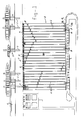
- the storage and trans-shipment site for containers shown in top view in Figures 1, 2 and 3 shows a quay 1 at which ships have been moored, a number of loading and unloading cranes 2 for containers known per se located on said quay, and a container storage depot with a number of ways 4 for gantry cranes.
- Each gantry craneway 4 in the embodiment shown in Figure 7 is rather more than five container widths in width, although obviously another multiple of the container width may also be used.
- two containers can be stacked on top of each other, while no containers are placed on top of each other in the intervening three storage places. Where there are six containers, two containers can be stacked on top of each other at the four (two x two) outermost storage places.
- Each car 5 has a lifting platform 6 that can be raised and lowered with respect to the chassis by a mechanical, pneumatic or hydraulic lifting mechanism.
- the containers are placed on a lifting platform 6 of the cars by a quay crane 2 ( Figure 5).
- Supporting tables 8 which are supported by legs 9 are placed in the buffer area between the cars and the container storage depot. The distance between the supporting tables 8 is smaller than the width of a container, whereas the distance between the legs 9 is larger than the widths of the cars 5.
- Each car can move through between the leg 9 with the lifting platform 6 raised and, by letting said platform down, puts a container down on two tables 8, where the container can be picked up by a gantry crane 11 at an arbitrary point in time.
- gantry-type skids ( Figure 6) may be used.
- the containers are placed on a skid 7 by the quay crane, a car 5 drives into a skid 7 with its chassis 5a lowered and the chassis with skid 7 and container are raised.
- the chassis is lowered again for putting down the gantry-type skid 7 with the container.
- the two alternative embodiments being the one with a lifting platform 6 and supporting tables 8 and the one with a vertically movable chassis respectively, have the advantage that each container can be stored temporarily at the start of the gantry craneways 4 so that said area can form a buffer.
- the possibility that the gantry cranes 11 lift the containers directly from the cars 5 or place them on top is not excluded, in which case the tables 8 and the gantry-type pallets 7 are not required and there is no buffer between the car system and the container storage depot.
- a buffer may also be formed where the quay cranes are located, for example because of the fact that supporting tables are hung on the quay cranes.
- Each car is provided with a navigation system, housed in a case 12, that is intended for automatic control of the car with the help of a freely programmable route selection system.
- This system is able to make the car drive along pre-programmed positions.
- the positions will usually be part of a system of co-ordinates.
- Figure 2 shows a part of such a system of co-ordinates, for which the pre-programmed command was: E3, B3, B12, M12, M15.
- the navigation means determine the path taken with the help of facilities known per se such as acceleration sensors, steering angle transducers, encoders (pulse counters for determining the number of revolutions of a wheel), radar, a laser gyro, or a combination of these, and compare the path taken with the path to be followed.
- facilities known per se such as acceleration sensors, steering angle transducers, encoders (pulse counters for determining the number of revolutions of a wheel), radar, a laser gyro, or a combination of these, and compare the path taken with the path to be followed.
- the control elements of the car (means of starting, fuel supply, braking, angle of the wheels and such like) are controlled such that the car will take the desired path.
- This position-determining system comprises a reference grid in, on or underneath the ground of the quay area and, on each car, one or more transmitter-receiver units that can interact with the reference grid in order to determine the exact position of the car. If this position deviates from the desired position, correction signals are sent to the control means of the car.
- This position-determining system comprises a reference grid in, on or underneath the ground of the quay area and, on each car, one or more transmitter-receiver units that can interact with the reference grid in order to determine the exact position of the car. If this position deviates from the desired position, correction signals are sent to the control means of the car.
- the transmitter-receiver units 14 In the case of a transponder grid the transmitter-receiver units 14 generate a wave signal that is broadcast via a transmission-detection spool. A transmission area is formed in which a transponder can be activated. The receiver receives a signal coded by registration of the change in impedance via the spool of the activated transponder, which signal is identified. The said detection spool forms in fact the connecting link between the transmitter-receiver and the transponder.
- the transponder system is a means for correcting errors in the navigation carried out by the cars themselves.
- the transponders are the control beacons.
- the receiver units of the cars can scan an electromagnetic field.
- the transmitter-receiver units consist of the metal detectors.
- transponders 13 are placed at the junctions of a grid of active or passive inductive wires. These wires could promote the accuracy and/or fluency of the movements of the cars. In this it can therefore be a matter of the combination of the possibilities mentioned above under 1 and 2.
- the successive co-ordinates of the co-ordinate system mentioned above are 8 metres apart, such that each rectangle has dimensions of 8 x 8 metres.
- transponders 13 are used, these are, for example, ordered as shown in Figure 2.
- the cars 5 will be provided with sensors to detect obstacles within braking distance and to bring the cars to a stop automatically if an obstacle is detected. This serves to prevent accidents.
- a central traffic guidance system will have to prevent the cars colliding with each other at paths which cross, or dead-lock situations arising.
- the cars are constructed symmetrically, there being no difference between driving forwards and backwards. They are intended for the transport of only one container.
- the containers may have different lengths.
- the lengths of the loading floor of the cars is adapted to the length of the longest container to be transported.
- the two sets of wheels of each car can be controlled independently, for example with hydraulic cylinders with electrically operated valves.
- Control of the gantry cranes 11 is similarly completely automatic. This applies to the movement of the whole crane along its rails, to the movement of the travelling trolley 10 across the direction of the rails and to the movements of the yoke 15 upwards and downwards, and to the hooking-on and -off of the container with the latter.
- Control of the cars includes distribution of the vehicle orders, traffic regulation, collision safeguards and route optimization. It also encompasses data communication with the cars.
- the process control is linked with a container control system that passes on the data on the containers to be loaded and unloaded and the identification data on incoming and departing containers to the process control.
- the process control comprises a traffic guidance system that receives information on the position, speed and direction of all deployed vehicles, and that calculates the room to be taken up by the car for each car path and determines the priority of one car over another. Further strictlymore the process control contains a vehicle control system that determines the vehicles which are available and regulates the even deployment of those vehicles.
- An order-regulation system issues orders to cars, gantry cranes and land side cranes.
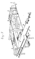
- Figure 7 shows the despatch of containers on the land side.
- the land side cranes 16 are movable along railways perpendicular to the tracks 4 of the gantry cranes 11. These railways of the land side cranes have one rail 17a at ground level and one raised rail 17b. The lorries to be loaded and unloaded can drive through underneath the raised rail 17b to a position within reach of the travelling trolley 18 of the crane 16. Next to the rail 17a there is in addition a part of a lane 19 for container transport means consisting of various container wagons 20 (multi-trailer system).
- the travelling trolley 18 of the land side cranes 16 has a turntable 21 with which the lifted containers can be turned through 90° or 180°.
- the picking-up or putting-down of the containers from or in, respectively, the buffer area between the land side cranes and the gantry cranes is done completely automatically, the process control for the whole system being switched on.
- the picking-up or putting-down of containers from or on, respectively, a lorry or multi-trailer system (MTS) is done partly manually.
- the containers are stored randomly in the warehouse.
- the lorry driver checking in gets an order to drive to a particular loading bay opposite a gantry craneway and in the meantime an order is given to the gantry crane in question to pick up a particular container from the storage depot and to bring it to the buffer area between the gantry crane and the land side crane, where the latter crane automatically picks up the container and brings it above the lorry.
Landscapes
- Engineering & Computer Science (AREA)
- Radar, Positioning & Navigation (AREA)
- Remote Sensing (AREA)
- Aviation & Aerospace Engineering (AREA)
- Physics & Mathematics (AREA)
- General Physics & Mathematics (AREA)
- Automation & Control Theory (AREA)
- Ship Loading And Unloading (AREA)
- Warehouses Or Storage Devices (AREA)
- Control And Safety Of Cranes (AREA)
Applications Claiming Priority (2)
| Application Number | Priority Date | Filing Date | Title |
|---|---|---|---|
| NL8701823 | 1987-08-03 | ||
| NL8701823A NL8701823A (nl) | 1987-08-03 | 1987-08-03 | Op- en overslagsysteem voor containers. |
Publications (2)
| Publication Number | Publication Date |
|---|---|
| EP0302569A1 true EP0302569A1 (de) | 1989-02-08 |
| EP0302569B1 EP0302569B1 (de) | 1991-05-15 |
Family
ID=19850406
Family Applications (1)
| Application Number | Title | Priority Date | Filing Date |
|---|---|---|---|
| EP88201671A Expired - Lifetime EP0302569B1 (de) | 1987-08-03 | 1988-08-02 | Lagerungs- und Verschiffungsanlage für Container |
Country Status (8)
| Country | Link |
|---|---|
| EP (1) | EP0302569B1 (de) |
| JP (1) | JPH01133820A (de) |
| DE (1) | DE3862825D1 (de) |
| ES (1) | ES2022596B3 (de) |
| GR (1) | GR3002200T3 (de) |
| HK (1) | HK95291A (de) |
| NL (1) | NL8701823A (de) |
| PT (1) | PT88176B (de) |
Cited By (23)
| Publication number | Priority date | Publication date | Assignee | Title |
|---|---|---|---|---|
| EP0341889A2 (de) * | 1988-05-13 | 1989-11-15 | Cegelec Controls Ltd. | Automatische Fahrzeugsteuerung |
| EP0388288A1 (de) * | 1989-03-14 | 1990-09-19 | Renault Automation | Robotisiertes System für Förderung |
| WO1990011561A1 (en) * | 1989-03-22 | 1990-10-04 | Caterpillar Industrial Inc. | System for loading and unloading trailers using automatic guided vehicles |
| FR2653416A1 (fr) * | 1989-10-24 | 1991-04-26 | Sncf | Installation et procede de manutention automatique de boites transportees par wagons de chemins de fer. |
| NL9300597A (nl) * | 1993-04-05 | 1994-11-01 | Terberg Benschop B V | Onbemand voertuig met schamelsturing. |
| DE29513080U1 (de) * | 1995-08-16 | 1996-11-21 | Wilms, Peter, 45731 Waltrop | Vorrichtung zur Aufnahme eines Containers |
| WO1998058861A1 (en) * | 1997-06-19 | 1998-12-30 | Rolux Transport Systems Ltd. | Method and apparatus for loading a vessel with containers and for unloading the vessel |
| WO2000018671A1 (en) * | 1998-09-30 | 2000-04-06 | Abb Ab | Horizontal reference marker |
| NL1030501C2 (nl) * | 2005-11-23 | 2007-05-24 | Univ Delft Tech | Regelsysteem, alsmede een in dit regelsysteem te gebruiken sensor en actuator. |
| EP1798169A2 (de) | 2005-12-14 | 2007-06-20 | Shanghai Zhenhua Port Machinery Co. Ltd. | System mit einem niedrigen Brückengestell und Trägern zum Umsetzen von Containern zwischen einem seeseitigen Kran und einem Kran eines Containerlagers |
| EP1861866A2 (de) | 2005-02-25 | 2007-12-05 | Maersk, Inc. | System und prozess zum verbessern des containerflusses in einer hafenanlage |
| EP2082981A1 (de) * | 2008-01-24 | 2009-07-29 | Shanghai Zhenhua Port Machinery Co., Ltd. | Belade-/Entladesystem für ein Containerterminal |
| EP2157041A1 (de) * | 2008-08-20 | 2010-02-24 | Siemens Aktiengesellschaft | Verfahren und System zur Ermittlung einer Position eines Objekts in einer Containerkrananlage und Steuerungsprogramm für eine Meßvorrichtung |
| US7686558B2 (en) * | 2006-04-20 | 2010-03-30 | Shanghai Zhenhua Port Machinery Co., Ltd. | Arrangement scheme of a container wharf and the container loading/unloading process |
| WO2010066602A1 (de) * | 2008-12-09 | 2010-06-17 | Gottwald Port Technology Gmbh | Verfahren und eine anlage zum umschlag von normierten ladungsträgern, insbesondere iso-containern und wechselaufbauten, zwischen schiene und strasse |
| DE102011089858A1 (de) * | 2011-12-23 | 2013-06-27 | Krones Ag | System zum Transport von auf Hilfsmitteln angeordneten Gütern |
| US20140086709A1 (en) * | 2011-03-29 | 2014-03-27 | Mitsui Engineering & Shipbuilding Co., Ltd. | Container terminal and control method thereof |
| WO2014207350A3 (fr) * | 2013-06-24 | 2015-03-12 | Batterie Mobile | Procédé de guidage d'un véhicule aéroportuaire |
| US9522623B2 (en) | 2010-11-11 | 2016-12-20 | Terex Mhps Gmbh | Heavy duty transport vehicle for ISO containers |
| US20180005181A1 (en) * | 2015-01-15 | 2018-01-04 | Batterie Mobile | Method of loading/unloading containers in a port facility |
| CN107826787A (zh) * | 2017-10-11 | 2018-03-23 | 广州蓝圣智能科技有限公司 | 门框上条堆垛自动化线 |
| JP6413158B1 (ja) * | 2017-07-10 | 2018-10-31 | 株式会社ベイビッグ | 位置管理システム及び位置管理方法 |
| WO2019218785A1 (zh) * | 2018-05-16 | 2019-11-21 | 青岛港国际股份有限公司 | 自动化集装箱装卸码头 |
Families Citing this family (11)
| Publication number | Priority date | Publication date | Assignee | Title |
|---|---|---|---|---|
| JPH04271453A (ja) * | 1991-02-27 | 1992-09-28 | Toshiba Corp | 複合電子計算機 |
| JP3820166B2 (ja) * | 2001-12-26 | 2006-09-13 | 三菱重工業株式会社 | 荷役システムおよび荷役システムの制御方法 |
| JP2005272144A (ja) * | 2004-02-24 | 2005-10-06 | Nippon Fruehauf Co Ltd | 海上コンテナ用ヤードシャーシ |
| JP4895678B2 (ja) * | 2006-05-22 | 2012-03-14 | 株式会社デンソー | 集積回路装置 |
| DE102007039778A1 (de) | 2007-08-23 | 2009-02-26 | Gottwald Port Technology Gmbh | Flurgebundenes Transportfahrzeug, insbesondere für den Transport von Containern |
| EP2079607B1 (de) | 2006-10-19 | 2010-07-07 | Gottwald Port Technology GmbH | Flurgebundenes transportfahrzeug, insbesondere für den transport von containern |
| DE102007039780A1 (de) | 2007-08-23 | 2009-02-26 | Gottwald Port Technology Gmbh | Vorrichtung zum Sichern eines Containers auf einer Plattform eines Transportfahrzeugs |
| DE102010060504A1 (de) | 2010-11-11 | 2012-05-16 | Gottwald Port Technology Gmbh | System für den Umschlag von Containern |
| DE102013114841A1 (de) * | 2013-12-23 | 2015-06-25 | Terex Mhps Gmbh | Flurgebundenes Transportfahrzeug für Container mit einer Hubfunktion |
| JP2015193435A (ja) * | 2014-03-31 | 2015-11-05 | 三井造船株式会社 | コンテナターミナル及びコンテナターミナルの運用方法 |
| JP6863746B2 (ja) * | 2017-01-04 | 2021-04-21 | 株式会社三井E&Sマシナリー | コンテナターミナル及びその運用方法 |
Citations (4)
| Publication number | Priority date | Publication date | Assignee | Title |
|---|---|---|---|---|
| NL6912396A (de) * | 1968-08-21 | 1970-02-24 | ||
| GB2042217A (en) * | 1979-02-05 | 1980-09-17 | Volvo Ab | Self-piloting vehicle |
| FR2526181A1 (fr) * | 1982-04-30 | 1983-11-04 | Traitement Information Tech Nl | Installation de transport automatique par chariots autonomes, et chariots autonomes pour une telle installation |
| DE3544705A1 (de) * | 1984-12-27 | 1986-07-17 | Mannesmann Demag Corp., Grand Rapids, Mich. | Passive programmierbare responder fuer fuehrungssysteme |
-
1987
- 1987-08-03 NL NL8701823A patent/NL8701823A/nl not_active Application Discontinuation
-
1988
- 1988-08-02 EP EP88201671A patent/EP0302569B1/de not_active Expired - Lifetime
- 1988-08-02 DE DE8888201671T patent/DE3862825D1/de not_active Expired - Fee Related
- 1988-08-02 PT PT88176A patent/PT88176B/pt not_active IP Right Cessation
- 1988-08-02 ES ES88201671T patent/ES2022596B3/es not_active Expired - Lifetime
- 1988-08-03 JP JP63195293A patent/JPH01133820A/ja active Pending
-
1991
- 1991-06-27 GR GR91400891T patent/GR3002200T3/el unknown
- 1991-11-28 HK HK952/91A patent/HK95291A/xx not_active IP Right Cessation
Patent Citations (4)
| Publication number | Priority date | Publication date | Assignee | Title |
|---|---|---|---|---|
| NL6912396A (de) * | 1968-08-21 | 1970-02-24 | ||
| GB2042217A (en) * | 1979-02-05 | 1980-09-17 | Volvo Ab | Self-piloting vehicle |
| FR2526181A1 (fr) * | 1982-04-30 | 1983-11-04 | Traitement Information Tech Nl | Installation de transport automatique par chariots autonomes, et chariots autonomes pour une telle installation |
| DE3544705A1 (de) * | 1984-12-27 | 1986-07-17 | Mannesmann Demag Corp., Grand Rapids, Mich. | Passive programmierbare responder fuer fuehrungssysteme |
Non-Patent Citations (1)
| Title |
|---|
| LE NOUVEL AUTOMATISME, vol. 28, no. 33, January/February 1983, pages 57-65; F. LEPAGE et al.: "Liaisons et protocoles d'information intra-entreprises" * |
Cited By (41)
| Publication number | Priority date | Publication date | Assignee | Title |
|---|---|---|---|---|
| EP0341889A2 (de) * | 1988-05-13 | 1989-11-15 | Cegelec Controls Ltd. | Automatische Fahrzeugsteuerung |
| EP0341889A3 (en) * | 1988-05-13 | 1990-12-19 | The General Electric Company, P.L.C. | Automated vehicle control |
| EP0388288A1 (de) * | 1989-03-14 | 1990-09-19 | Renault Automation | Robotisiertes System für Förderung |
| FR2644599A1 (fr) * | 1989-03-14 | 1990-09-21 | Renault Automation | Systeme robotise de manutention |
| WO1990011561A1 (en) * | 1989-03-22 | 1990-10-04 | Caterpillar Industrial Inc. | System for loading and unloading trailers using automatic guided vehicles |
| FR2653416A1 (fr) * | 1989-10-24 | 1991-04-26 | Sncf | Installation et procede de manutention automatique de boites transportees par wagons de chemins de fer. |
| EP0426528A2 (de) * | 1989-10-24 | 1991-05-08 | Societe Nationale Des Chemins De Fer Francais | Einrichtung und Verfahren zum Handhaben von Behältern, die auf Eisenbahnwagen transportiert werden |
| EP0426528A3 (en) * | 1989-10-24 | 1991-08-21 | Societe Nationale Des Chemins De Fer Francais | Installation and procedure for handling containers transported on railway cars |
| NL9300597A (nl) * | 1993-04-05 | 1994-11-01 | Terberg Benschop B V | Onbemand voertuig met schamelsturing. |
| DE29513080U1 (de) * | 1995-08-16 | 1996-11-21 | Wilms, Peter, 45731 Waltrop | Vorrichtung zur Aufnahme eines Containers |
| WO1998058861A1 (en) * | 1997-06-19 | 1998-12-30 | Rolux Transport Systems Ltd. | Method and apparatus for loading a vessel with containers and for unloading the vessel |
| WO2000018671A1 (en) * | 1998-09-30 | 2000-04-06 | Abb Ab | Horizontal reference marker |
| US6535834B1 (en) | 1998-09-30 | 2003-03-18 | Abb Ab | Horizontal reference marker |
| EP1861866A2 (de) | 2005-02-25 | 2007-12-05 | Maersk, Inc. | System und prozess zum verbessern des containerflusses in einer hafenanlage |
| US8306649B2 (en) | 2005-02-25 | 2012-11-06 | Apm Terminals North America, Inc. | System and process for improving container flow in a port facility |
| US7987017B2 (en) | 2005-02-25 | 2011-07-26 | Apm Terminals North America, Inc. | System and process for improving container flow in a port facility |
| EP1861866A4 (de) * | 2005-02-25 | 2010-05-26 | Maersk Inc | System und prozess zum verbessern des containerflusses in einer hafenanlage |
| NL1030501C2 (nl) * | 2005-11-23 | 2007-05-24 | Univ Delft Tech | Regelsysteem, alsmede een in dit regelsysteem te gebruiken sensor en actuator. |
| WO2007061306A1 (en) * | 2005-11-23 | 2007-05-31 | Technische Universiteit Delft | Control system, and a sensor and actuator to be used in this control system |
| EP1798169A2 (de) | 2005-12-14 | 2007-06-20 | Shanghai Zhenhua Port Machinery Co. Ltd. | System mit einem niedrigen Brückengestell und Trägern zum Umsetzen von Containern zwischen einem seeseitigen Kran und einem Kran eines Containerlagers |
| EP1798169A3 (de) * | 2005-12-14 | 2009-01-14 | Shanghai Zhenhua Port Machinery Co. Ltd. | System mit einem niedrigen Brückengestell und Trägern zum Umsetzen von Containern zwischen einem seeseitigen Kran und einem Kran eines Containerlagers |
| US7686558B2 (en) * | 2006-04-20 | 2010-03-30 | Shanghai Zhenhua Port Machinery Co., Ltd. | Arrangement scheme of a container wharf and the container loading/unloading process |
| US8087867B2 (en) | 2008-01-24 | 2012-01-03 | Shanhai Zhenhua Port Machinery Co. Ltd. | Loading/unloading system for container terminal |
| EP2082981A1 (de) * | 2008-01-24 | 2009-07-29 | Shanghai Zhenhua Port Machinery Co., Ltd. | Belade-/Entladesystem für ein Containerterminal |
| EP2157041A1 (de) * | 2008-08-20 | 2010-02-24 | Siemens Aktiengesellschaft | Verfahren und System zur Ermittlung einer Position eines Objekts in einer Containerkrananlage und Steuerungsprogramm für eine Meßvorrichtung |
| CN101655348B (zh) * | 2008-08-20 | 2012-04-11 | 西门子公司 | 测定集装箱起重机设备中对象位置的方法和系统 |
| US8651793B2 (en) | 2008-12-09 | 2014-02-18 | Gottwald Port Technology, GmbH | Method and system for transferring standard cargo holders, especially ISO containers and swap bodies, between railways and roads |
| WO2010066602A1 (de) * | 2008-12-09 | 2010-06-17 | Gottwald Port Technology Gmbh | Verfahren und eine anlage zum umschlag von normierten ladungsträgern, insbesondere iso-containern und wechselaufbauten, zwischen schiene und strasse |
| US9522623B2 (en) | 2010-11-11 | 2016-12-20 | Terex Mhps Gmbh | Heavy duty transport vehicle for ISO containers |
| US20140086709A1 (en) * | 2011-03-29 | 2014-03-27 | Mitsui Engineering & Shipbuilding Co., Ltd. | Container terminal and control method thereof |
| US9452900B2 (en) * | 2011-03-29 | 2016-09-27 | Mitsui Engineering & Shipbuilding Co., Ltd. | Container terminal and control method thereof |
| US8989918B2 (en) | 2011-12-23 | 2015-03-24 | Krones Ag | System for transporting goods arranged on auxiliary devices |
| DE102011089858A1 (de) * | 2011-12-23 | 2013-06-27 | Krones Ag | System zum Transport von auf Hilfsmitteln angeordneten Gütern |
| WO2014207350A3 (fr) * | 2013-06-24 | 2015-03-12 | Batterie Mobile | Procédé de guidage d'un véhicule aéroportuaire |
| US9446918B2 (en) | 2013-06-24 | 2016-09-20 | Batterie Mobile | Method for steering an airport vehicle |
| US20180005181A1 (en) * | 2015-01-15 | 2018-01-04 | Batterie Mobile | Method of loading/unloading containers in a port facility |
| JP6413158B1 (ja) * | 2017-07-10 | 2018-10-31 | 株式会社ベイビッグ | 位置管理システム及び位置管理方法 |
| JP2019014593A (ja) * | 2017-07-10 | 2019-01-31 | 株式会社ベイビッグ | 位置管理システム及び位置管理方法 |
| CN107826787A (zh) * | 2017-10-11 | 2018-03-23 | 广州蓝圣智能科技有限公司 | 门框上条堆垛自动化线 |
| CN107826787B (zh) * | 2017-10-11 | 2024-01-12 | 湖北敏实汽车零部件有限公司 | 门框上条堆垛自动化线 |
| WO2019218785A1 (zh) * | 2018-05-16 | 2019-11-21 | 青岛港国际股份有限公司 | 自动化集装箱装卸码头 |
Also Published As
| Publication number | Publication date |
|---|---|
| HK95291A (en) | 1991-12-06 |
| DE3862825D1 (de) | 1991-06-20 |
| GR3002200T3 (en) | 1992-12-30 |
| NL8701823A (nl) | 1989-03-01 |
| PT88176A (pt) | 1989-06-30 |
| EP0302569B1 (de) | 1991-05-15 |
| ES2022596B3 (es) | 1991-12-01 |
| PT88176B (pt) | 1993-09-30 |
| JPH01133820A (ja) | 1989-05-25 |
Similar Documents
| Publication | Publication Date | Title |
|---|---|---|
| EP0302569B1 (de) | Lagerungs- und Verschiffungsanlage für Container | |
| KR101923744B1 (ko) | 선택적으로 무인 또는 유인 방식으로 동작될 수 있는 지상에서 주행하는 고무 타이어를 구비하는 컨테이너 운반 차량 | |
| KR102625918B1 (ko) | 컨테이너 자동 안내 운송 차량 및 그 작동 방법, 및 자동 운전 운송 차량을 갖는 시스템 | |
| US3669206A (en) | Container transporting system | |
| CN109952267B (zh) | 用于装卸集装箱的跨运车形式的门式起重装置的导航系统 | |
| CN110622082B (zh) | 用于操作用于集装箱的自动引导的运输车辆的方法和系统 | |
| US3700128A (en) | Intermodal transfer system | |
| CN109661362B (zh) | 通过重型车辆运输集装箱、尤其是iso集装箱的系统 | |
| AU2009200433A1 (en) | Fully automatic straddle carrier with local radio detection and laser steering | |
| KR102366916B1 (ko) | 대형 수송 차량을 이용한 컨테이너 특히, iso 컨테이너 운송 시스템 | |
| JP2001512259A (ja) | 車両の制御システムおよび方法 | |
| US7044247B2 (en) | Device at Ro-Ro vessel | |
| US20210147192A1 (en) | Automatically guided lifting gantry device for containers and method for operating such a lifting gantry device | |
| CN111094159B (zh) | 用于在集装箱集散终端中控制运输车辆的在集装箱的转运区域内的行进的方法、其控制系统和包括这种控制系统的集散终端 | |
| CN101269751A (zh) | 用于集装箱装载设备的定位系统 | |
| CN110446674B (zh) | 集装箱的仓储和在这种类型的仓储中操作运输车辆的方法 | |
| JP6492324B2 (ja) | コンテナターミナル | |
| AU675241B2 (en) | Process for transferring goods load units on or from a train and device for implementing the process | |
| CN111606200B (zh) | 传感器小车以及对应的集装箱起重机 | |
| JP2001322720A (ja) | コンテナ荷役方法およびコンテナ荷役システム | |
| CN110944926A (zh) | 用于无线电定位用于集装箱的运输车辆的系统 | |
| EP1594782B1 (de) | Umschlagsystem für container | |
| JPH0561538A (ja) | 運搬台車の走行制御方法 | |
| FI109242B (fi) | Automaattinen suoraanajojärjestelmä kontinkäsittelykonetta varten | |
| JPS5854049B2 (ja) | 長尺物の積層保管装置 |
Legal Events
| Date | Code | Title | Description |
|---|---|---|---|
| PUAI | Public reference made under article 153(3) epc to a published international application that has entered the european phase |
Free format text: ORIGINAL CODE: 0009012 |
|
| AK | Designated contracting states |
Kind code of ref document: A1 Designated state(s): BE DE ES FR GB GR IT NL SE |
|
| 17P | Request for examination filed |
Effective date: 19890202 |
|
| 17Q | First examination report despatched |
Effective date: 19901022 |
|
| GRAA | (expected) grant |
Free format text: ORIGINAL CODE: 0009210 |
|
| AK | Designated contracting states |
Kind code of ref document: B1 Designated state(s): BE DE ES FR GB GR IT NL SE |
|
| REF | Corresponds to: |
Ref document number: 3862825 Country of ref document: DE Date of ref document: 19910620 |
|
| ET | Fr: translation filed | ||
| ITF | It: translation for a ep patent filed | ||
| PLBE | No opposition filed within time limit |
Free format text: ORIGINAL CODE: 0009261 |
|
| STAA | Information on the status of an ep patent application or granted ep patent |
Free format text: STATUS: NO OPPOSITION FILED WITHIN TIME LIMIT |
|
| 26N | No opposition filed | ||
| REG | Reference to a national code |
Ref country code: GR Ref legal event code: FG4A Free format text: 3002200 |
|
| EAL | Se: european patent in force in sweden |
Ref document number: 88201671.0 |
|
| PGFP | Annual fee paid to national office [announced via postgrant information from national office to epo] |
Ref country code: GR Payment date: 19970806 Year of fee payment: 10 |
|
| PGFP | Annual fee paid to national office [announced via postgrant information from national office to epo] |
Ref country code: ES Payment date: 19970812 Year of fee payment: 10 |
|
| PGFP | Annual fee paid to national office [announced via postgrant information from national office to epo] |
Ref country code: SE Payment date: 19970818 Year of fee payment: 10 |
|
| PG25 | Lapsed in a contracting state [announced via postgrant information from national office to epo] |
Ref country code: SE Free format text: LAPSE BECAUSE OF NON-PAYMENT OF DUE FEES Effective date: 19980803 Ref country code: ES Free format text: LAPSE BECAUSE OF EXPIRATION OF PROTECTION Effective date: 19980803 |
|
| PG25 | Lapsed in a contracting state [announced via postgrant information from national office to epo] |
Ref country code: GR Free format text: LAPSE BECAUSE OF NON-PAYMENT OF DUE FEES Effective date: 19980831 |
|
| EUG | Se: european patent has lapsed |
Ref document number: 88201671.0 |
|
| PGFP | Annual fee paid to national office [announced via postgrant information from national office to epo] |
Ref country code: DE Payment date: 20000729 Year of fee payment: 13 |
|
| PGFP | Annual fee paid to national office [announced via postgrant information from national office to epo] |
Ref country code: GB Payment date: 20000802 Year of fee payment: 13 |
|
| PGFP | Annual fee paid to national office [announced via postgrant information from national office to epo] |
Ref country code: FR Payment date: 20000811 Year of fee payment: 13 |
|
| PGFP | Annual fee paid to national office [announced via postgrant information from national office to epo] |
Ref country code: NL Payment date: 20000831 Year of fee payment: 13 |
|
| PGFP | Annual fee paid to national office [announced via postgrant information from national office to epo] |
Ref country code: BE Payment date: 20001025 Year of fee payment: 13 |
|
| REG | Reference to a national code |
Ref country code: ES Ref legal event code: FD2A Effective date: 20010201 |
|
| PG25 | Lapsed in a contracting state [announced via postgrant information from national office to epo] |
Ref country code: GB Free format text: LAPSE BECAUSE OF NON-PAYMENT OF DUE FEES Effective date: 20010802 |
|
| PG25 | Lapsed in a contracting state [announced via postgrant information from national office to epo] |
Ref country code: BE Free format text: LAPSE BECAUSE OF NON-PAYMENT OF DUE FEES Effective date: 20010831 |
|
| BERE | Be: lapsed |
Owner name: EUROPE CONTAINER TERMINUS B.V. Effective date: 20010831 |
|
| PG25 | Lapsed in a contracting state [announced via postgrant information from national office to epo] |
Ref country code: NL Free format text: LAPSE BECAUSE OF NON-PAYMENT OF DUE FEES Effective date: 20020301 |
|
| GBPC | Gb: european patent ceased through non-payment of renewal fee |
Effective date: 20010802 |
|
| PG25 | Lapsed in a contracting state [announced via postgrant information from national office to epo] |
Ref country code: FR Free format text: LAPSE BECAUSE OF NON-PAYMENT OF DUE FEES Effective date: 20020430 |
|
| NLV4 | Nl: lapsed or anulled due to non-payment of the annual fee |
Effective date: 20020301 |
|
| PG25 | Lapsed in a contracting state [announced via postgrant information from national office to epo] |
Ref country code: DE Free format text: LAPSE BECAUSE OF NON-PAYMENT OF DUE FEES Effective date: 20020501 |
|
| REG | Reference to a national code |
Ref country code: FR Ref legal event code: ST |
|
| PG25 | Lapsed in a contracting state [announced via postgrant information from national office to epo] |
Ref country code: IT Free format text: LAPSE BECAUSE OF NON-PAYMENT OF DUE FEES;WARNING: LAPSES OF ITALIAN PATENTS WITH EFFECTIVE DATE BEFORE 2007 MAY HAVE OCCURRED AT ANY TIME BEFORE 2007. THE CORRECT EFFECTIVE DATE MAY BE DIFFERENT FROM THE ONE RECORDED. Effective date: 20050802 |