EP0302446A2 - Gasregelventil - Google Patents
Gasregelventil Download PDFInfo
- Publication number
- EP0302446A2 EP0302446A2 EP88112534A EP88112534A EP0302446A2 EP 0302446 A2 EP0302446 A2 EP 0302446A2 EP 88112534 A EP88112534 A EP 88112534A EP 88112534 A EP88112534 A EP 88112534A EP 0302446 A2 EP0302446 A2 EP 0302446A2
- Authority
- EP
- European Patent Office
- Prior art keywords
- valve
- closure member
- outlet
- control
- valve seat
- Prior art date
- Legal status (The legal status is an assumption and is not a legal conclusion. Google has not performed a legal analysis and makes no representation as to the accuracy of the status listed.)
- Withdrawn
Links
Images

Classifications
-
- F—MECHANICAL ENGINEERING; LIGHTING; HEATING; WEAPONS; BLASTING
- F23—COMBUSTION APPARATUS; COMBUSTION PROCESSES
- F23N—REGULATING OR CONTROLLING COMBUSTION
- F23N5/00—Systems for controlling combustion
- F23N5/02—Systems for controlling combustion using devices responsive to thermal changes or to thermal expansion of a medium
- F23N5/10—Systems for controlling combustion using devices responsive to thermal changes or to thermal expansion of a medium using thermocouples
- F23N5/107—Systems for controlling combustion using devices responsive to thermal changes or to thermal expansion of a medium using thermocouples using mechanical means, e.g. safety valves
-
- F—MECHANICAL ENGINEERING; LIGHTING; HEATING; WEAPONS; BLASTING
- F23—COMBUSTION APPARATUS; COMBUSTION PROCESSES
- F23N—REGULATING OR CONTROLLING COMBUSTION
- F23N2235/00—Valves, nozzles or pumps
- F23N2235/12—Fuel valves
- F23N2235/14—Fuel valves electromagnetically operated
-
- F—MECHANICAL ENGINEERING; LIGHTING; HEATING; WEAPONS; BLASTING
- F23—COMBUSTION APPARATUS; COMBUSTION PROCESSES
- F23N—REGULATING OR CONTROLLING COMBUSTION
- F23N2235/00—Valves, nozzles or pumps
- F23N2235/12—Fuel valves
- F23N2235/18—Groups of two or more valves
-
- F—MECHANICAL ENGINEERING; LIGHTING; HEATING; WEAPONS; BLASTING
- F23—COMBUSTION APPARATUS; COMBUSTION PROCESSES
- F23N—REGULATING OR CONTROLLING COMBUSTION
- F23N2235/00—Valves, nozzles or pumps
- F23N2235/12—Fuel valves
- F23N2235/24—Valve details
-
- Y—GENERAL TAGGING OF NEW TECHNOLOGICAL DEVELOPMENTS; GENERAL TAGGING OF CROSS-SECTIONAL TECHNOLOGIES SPANNING OVER SEVERAL SECTIONS OF THE IPC; TECHNICAL SUBJECTS COVERED BY FORMER USPC CROSS-REFERENCE ART COLLECTIONS [XRACs] AND DIGESTS
- Y10—TECHNICAL SUBJECTS COVERED BY FORMER USPC
- Y10T—TECHNICAL SUBJECTS COVERED BY FORMER US CLASSIFICATION
- Y10T137/00—Fluid handling
- Y10T137/7722—Line condition change responsive valves
- Y10T137/7781—With separate connected fluid reactor surface
- Y10T137/7835—Valve seating in direction of flow
- Y10T137/7836—Flexible diaphragm or bellows reactor
-
- Y—GENERAL TAGGING OF NEW TECHNOLOGICAL DEVELOPMENTS; GENERAL TAGGING OF CROSS-SECTIONAL TECHNOLOGIES SPANNING OVER SEVERAL SECTIONS OF THE IPC; TECHNICAL SUBJECTS COVERED BY FORMER USPC CROSS-REFERENCE ART COLLECTIONS [XRACs] AND DIGESTS
- Y10—TECHNICAL SUBJECTS COVERED BY FORMER USPC
- Y10T—TECHNICAL SUBJECTS COVERED BY FORMER US CLASSIFICATION
- Y10T137/00—Fluid handling
- Y10T137/8593—Systems
- Y10T137/87917—Flow path with serial valves and/or closures
Definitions
- the present invention relates to fluid pressure operated valves in particular gas valves. It is the main object of the invention to provide an improved gas control apparatus having separately characterized opening and closing operations; in particular it is desired to open the valve slowly but to close it quickly. These objects are accomplished by the invention as characterized in claim 1.
- the inlet gas pressure on the one side opens the main valve but on the other side is used to delay such opening so that the main valve opens slowly. For closing the valve this inlet pressure again is used for generating a force quickly closing the main valve by assisting the force of a bias spring acting in closing direction of the main valve closure member.
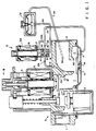
- a gas valve structure A having an inlet 1 and an outlet 2.
- a safety valve device 3 using a thermocouple is located in the gas flow path within the valve A.
- a first electromagnetic control valve B comprises an armature 4, a valve closure member 4A mounted on the armature 4, a valve seat 4B facing the closure member 4A and a solenoid winding 5.
- a diaphragm operated control valve C having a valve closure member or diaphragm 6 urged by a spring 10 against a valve seat 6A is located subsequent to the aforesaid valve B and prior to the outlet 2.
- the spring 10 is located in a chamber 11 beneath the diaphragm 10.
- the valve structure A is a well-known valve which is sold by Honeywell Inc. and identified as VR8200 Dual Valve Standing Pilot Gas Valve and is described in U.S. Patent No. 4,543,974.
- valve closure member 6 is ordinarily held against the valve seat 6A by the spring 10 to interrupt the gas flow through the valve C to the outlet 2.
- This valving action is in series with that provided by the aforesaid electromagnetically controlled armature 4 and solenoid coil 5.
- the armature 4 is actuated to open the associated valve seat 4B and allow an inlet gas from the inlet 1 to enter an internal chamber 7 leading to the valve seat 6A and closure member 6.
- An outlet port 12 is provided in the chamber 7 and is connected by a gas line 13 having an internal flow restriction 13A to an inlet of a second electromagnetically controlled valve D having an armature 15 and a solenoid winding 15A.
- An extension 17 of armature 15 is connected to a valve closure member 16.
- the valve closure member 16 is arranged to be operatively associated with a first valve seat 18 in a deenergized state of the winding 15A and a second valve seat 20 in an energized state of the winding 15A.
- valve D In the deenergized state of valve D, the gas flow through the port 12 and the gas pipe 13 is able to enter the space between the valve seats 18,20 and flow out to a second pipeline 24 through a restricted pipe line segment 26 having an internal restriction 28 connected to the space between the valve seats 18,20 and to flow along the armature extension 17 to an unrestricted bypass line 24A which is connected to the gas line 24.
- the flow of the gas into the gas line 24 is effective to fill the chamber 11 below the valve closure member 6.
- a high gas pressure is established on both sides of the valve closure member 6, and the area of exposure to the gas on the underside of the valve closure member 6 is arranged to maintain the valve closure member 6 against the valve seat 6A in combination with the spring 10.
- the armature 15 Upon an energization of the winding 15A of the valve D, the armature 15 is actuated to transfer the valve closure member 16 from the first valve seat 18 to the second valve seat 20. In this position, the gas flow path through the gas line 24, the restricted pipe segment 26 is directed through the valve seat 18 to allow a gas flow into a gas pipeline 30.
- the gas pipeline 30 is connected through a gas pressure regulator 32 to a gas pipeline 34, and ultimately, to a port 36 located in the outlet 2 from the gas valve A. This position of the closure member 16 enables the gas beneath the closure member 6 in the chamber 11 to bleed-off through the pipeline 24 and the restriction 28 in pipeline 26 to pipeline 30 leading to the pressure regulator 32.
- valve closure member 6 This slow bleeding of the gas from the underside of the valve closure member 6 causes this valve closure member to open slowly in response to the gas pressure exerted on the other side of the valve closure member 6 from the inlet 1.
- the valve closure member 6 maintains a final position depending upon the calibration of the regulator 32 to provide a desired gas flow from the outlet 2.
- the purpose of having the valve open slowly is to prevent a puffing or blow back of the gas ignition in a combustion chamber (not shown) supplied by the valve A.
- valve closure member 16 When the valve D is deenergized by a deenergization of the solenoid 15A, the valve closure member 16 is reapplied against the valve seat 18. This position of the valve closure member 16 is effective to open the valve seat 20 which allows the gas entering the port 12 to be conducted through the bypass 24A and the pipeline 24 to the underside of the valve closure member 6. This is effective to rapidly fill the chamber 11 below the valve closure member 6 and close the valve closure member 6 against the valve seat 6A at a fast rate.
- the purpose of the fast closure is to ensure that valve C is completely closed since should the solenoid 5 in valve B be recycled at a fast rate for a short cycle and if the valve C remains open it would be possible for the inlet gas to enter the appliance combustion chamber through the valve A without ignition to create a potentially explosive gas accumulation.
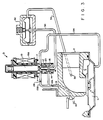
- FIG. 2 there is shown a partial cross-sectional illustration of a gas valve embodying a second example of the present invention.
- the port 12 and gas line 13 are connected to an inlet of the electromagnetically controlled valve D which is above the valve seat 20.
- An internal gas passage 21 in valve D is arranged to connect line 13 to the space between the valve seats 18 and 20.
- the bypass line 24A is connected within the valve D to the valve seat 20 and is arranged to be closed by the closure member 16 when solenoid 15A is energized.
- the gas pressure through line 13 is conducted through gas conduit 21 to fill chamber 11 through bypass 24A and pipeline 24 when solenoid coil 15A is deenergized.
- bypass line 24A is closed by valve closure member 16 after transfer thereof to the valve seat 23 while gas from the chamber 11 is allowed to bleed-off through pipeline 24 and pipeline 26 containing restriction 28 to pipeline 30 through the open valve seat 18.
- This enables a slow opening of the valve closure member 6 from the valve seat 6A.
- the valve closure member 16 is returned to the valve seat 18 to close-off the pipeline 30, and the gas from the port 12 and pipeline 13 is allowed to pass through conduit 21, bypass 24A and pipeline 24 to quickly fill chamber 11 and urge a fast closure of the valve closure member 6 against valve seat 6A.
- this structure is also effective to provide slow opening and fast closure operations of the valve structure.
- FIG. 3 there is shown a partial cross-section illustration of a third example of the present invention wherein pipeline 13 which is connected to one side of valve seat 20 as shown in Fig. 1 is also connected by an added bypass line 13B to the other side of valve seat 20 past the armature 17.
- the bypass line 13B has the internal restriction 28 therein and connects to the pipe line 13 after the flow control element 13A, i.e., on the valve D side of element 13A.
- armature 17 is provided with a plurality of surface grooves to enable a gas flow to be established therethrough.
- pipeline 24 is connected only to the same side of valve seat 20 as the bypass line 13B.
- valve closure member 16 allows a gas flow through the bypass 13A, past the valve seat 20 and the grooves around the armature extension 17 to produce a fast closure of valve C by quickly filling chamber 11.
- valve closure member 16 is transferred from the first valve seat 16 to the second valve seat 20.
- the gas flow path from gas line 24 is through bypass line 13B and restriction 28 to pipeline 13 and, ultimately, past the valve seat 18 to pipeline 30 to regulator 32 and pipeline 34 leading to exit port 36.
- This allows a slow bleed-off of the pressure in chamber 11 which causes the valve C to open slowly in response to the inlet gas pressure.
- the embodiment shown in Fig. 3 also provides slow opening and fast closure operations of the valve.
- an improved gas valve having separately characterized opening and closing rates.
Landscapes
- Engineering & Computer Science (AREA)
- Chemical & Material Sciences (AREA)
- Combustion & Propulsion (AREA)
- Mechanical Engineering (AREA)
- General Engineering & Computer Science (AREA)
- Magnetically Actuated Valves (AREA)
- Safety Valves (AREA)
Applications Claiming Priority (2)
| Application Number | Priority Date | Filing Date | Title |
|---|---|---|---|
| US82457 | 1987-08-07 | ||
| US07/082,457 US4790352A (en) | 1987-08-07 | 1987-08-07 | Slow opening and fast closure gas valve |
Publications (2)
| Publication Number | Publication Date |
|---|---|
| EP0302446A2 true EP0302446A2 (de) | 1989-02-08 |
| EP0302446A3 EP0302446A3 (de) | 1990-03-14 |
Family
ID=22171342
Family Applications (1)
| Application Number | Title | Priority Date | Filing Date |
|---|---|---|---|
| EP88112534A Withdrawn EP0302446A3 (de) | 1987-08-07 | 1988-08-02 | Gasregelventil |
Country Status (5)
| Country | Link |
|---|---|
| US (1) | US4790352A (de) |
| EP (1) | EP0302446A3 (de) |
| JP (1) | JPS6449780A (de) |
| CA (1) | CA1296237C (de) |
| DK (1) | DK271788A (de) |
Families Citing this family (15)
| Publication number | Priority date | Publication date | Assignee | Title |
|---|---|---|---|---|
| US5345963A (en) * | 1993-03-31 | 1994-09-13 | Honeywell Inc. | Modulating pressure regulator with shape memory alloy actuator |
| US5413141A (en) * | 1994-01-07 | 1995-05-09 | Honeywell Inc. | Two-stage gas valve with natural/LP gas conversion capability |
| US5944257A (en) | 1996-11-15 | 1999-08-31 | Honeywell Inc. | Bulb-operated modulating gas valve with minimum bypass |
| KR20010081220A (ko) * | 2000-02-11 | 2001-08-29 | 호메 윌리암 | 비례 조절 가스 밸브 |
| US6923204B2 (en) * | 2003-04-10 | 2005-08-02 | Honeywell International Inc. | Diaphragm-operated fluid flow control valve providing a plurality of flow levels |
| US20080268388A1 (en) * | 2005-11-23 | 2008-10-30 | Sit La Precisa S.P.A, | Device for Controlling the Delivery of a Combustible Gas to a Burner Apparatus |
| US7789657B2 (en) * | 2007-10-03 | 2010-09-07 | Honeywell International Inc. | Pressure regulator with bleed orifice |
| WO2009136715A2 (ko) * | 2008-05-06 | 2009-11-12 | 주식회사 대우일렉트로닉스 | 가스히터용 밸브 |
| US8381760B2 (en) | 2008-07-14 | 2013-02-26 | Emerson Electric Co. | Stepper motor valve and method of control |
| US8746275B2 (en) | 2008-07-14 | 2014-06-10 | Emerson Electric Co. | Gas valve and method of control |
| US8235064B2 (en) * | 2009-05-08 | 2012-08-07 | Honeywell International Inc. | Single coil redundant valve |
| US10006664B2 (en) * | 2015-05-11 | 2018-06-26 | Emerson Electric Co. | Slow opening and fast closing gas valves and related methods |
| US10993546B2 (en) | 2016-10-28 | 2021-05-04 | Sleep Number Corporation | Noise reducing plunger |
| CN107795279B (zh) * | 2017-12-06 | 2024-07-30 | 江苏徐工工程机械研究院有限公司 | 钻井机和工程车辆 |
| US11832728B2 (en) | 2021-08-24 | 2023-12-05 | Sleep Number Corporation | Controlling vibration transmission within inflation assemblies |
Family Cites Families (12)
| Publication number | Priority date | Publication date | Assignee | Title |
|---|---|---|---|---|
| US2902052A (en) * | 1954-03-22 | 1959-09-01 | Clark Controller Co | Magnetic valves |
| US3090592A (en) * | 1959-05-18 | 1963-05-21 | White Rodgers Company | Stepped-opening diaphragm gas valve |
| DE1208960B (de) * | 1962-11-09 | 1966-01-13 | Fr Buschjost O H G | Absperrventil mit Antrieb durch das abzusperrende Druckmittel, einem Hilfsventil und einem Rueckschlagventil |
| US3300174A (en) * | 1963-05-10 | 1967-01-24 | Emerson Electric Co | Gas valve |
| US3282556A (en) * | 1964-06-12 | 1966-11-01 | Hoffman Specialty Mfg Corp | Throttling button for diaphragm valve |
| US3304002A (en) * | 1965-01-18 | 1967-02-14 | Itt | Dual-piloted thermostatically controlled diaphragm valve |
| US3447775A (en) * | 1965-03-25 | 1969-06-03 | Robertshaw Controls Co | Diaphragm valve control |
| US3525355A (en) * | 1967-10-13 | 1970-08-25 | Robertshaw Controls Co | Flow control apparatus |
| US3526360A (en) * | 1968-10-18 | 1970-09-01 | Itt | Main line valve with pilot regulator |
| FR2250059B1 (de) * | 1973-10-31 | 1976-10-01 | Sefa Sa | |
| US4254796A (en) * | 1979-10-18 | 1981-03-10 | Robertshaw Controls Company | Gas regulator valve with step opening characteristic |
| US4543974A (en) * | 1982-09-14 | 1985-10-01 | Honeywell Inc. | Gas valve with combined manual and automatic operation |
-
1987
- 1987-08-07 US US07/082,457 patent/US4790352A/en not_active Expired - Lifetime
-
1988
- 1988-05-18 DK DK271788A patent/DK271788A/da not_active Application Discontinuation
- 1988-07-07 CA CA000571373A patent/CA1296237C/en not_active Expired - Fee Related
- 1988-07-22 JP JP63183420A patent/JPS6449780A/ja active Pending
- 1988-08-02 EP EP88112534A patent/EP0302446A3/de not_active Withdrawn
Also Published As
| Publication number | Publication date |
|---|---|
| JPS6449780A (en) | 1989-02-27 |
| EP0302446A3 (de) | 1990-03-14 |
| CA1296237C (en) | 1992-02-25 |
| DK271788A (da) | 1989-02-08 |
| US4790352A (en) | 1988-12-13 |
| DK271788D0 (da) | 1988-05-18 |
Similar Documents
| Publication | Publication Date | Title |
|---|---|---|
| EP0302446A2 (de) | Gasregelventil | |
| US5735503A (en) | Servo pressure regulator for a gas valve | |
| EP0744047B1 (de) | Absperr- und regelventil | |
| US6092545A (en) | Magnetic actuated valve | |
| US3957244A (en) | Valve | |
| CA2113024A1 (en) | High Pressure Relief System | |
| US2799293A (en) | Quick exhaust valve | |
| JPH1182763A (ja) | 空気圧駆動用の開閉制御弁及びその制御装置 | |
| US3721263A (en) | Stepped opening fluid pressure operated valve | |
| US3111960A (en) | Three way valve | |
| US3502101A (en) | Thermostatic control device with a pressure regulated stepped opened diaphragm valve | |
| JPH05158552A (ja) | 圧力制御弁 | |
| JP3025395B2 (ja) | 流量制御弁装置 | |
| GB1232445A (de) | ||
| US4457328A (en) | Combined positive seal and repetitive actuation isolation valve | |
| JPS5618173A (en) | Solenoid valve | |
| US3477462A (en) | High capacity pressure regulated gas diaphragm valve | |
| JP2757212B2 (ja) | 緊急遮断弁 | |
| JP4017280B2 (ja) | 流体供給遮断設備 | |
| RU2093748C1 (ru) | Отсечной клапан | |
| GB672696A (en) | A fluid pressure operated valve device | |
| JPS626150B2 (de) | ||
| GB1576677A (en) | Gas valve assembly | |
| JPH03620Y2 (de) | ||
| JPH03619Y2 (de) |
Legal Events
| Date | Code | Title | Description |
|---|---|---|---|
| PUAI | Public reference made under article 153(3) epc to a published international application that has entered the european phase |
Free format text: ORIGINAL CODE: 0009012 |
|
| AK | Designated contracting states |
Kind code of ref document: A2 Designated state(s): BE DE FR GB IT NL |
|
| PUAL | Search report despatched |
Free format text: ORIGINAL CODE: 0009013 |
|
| AK | Designated contracting states |
Kind code of ref document: A3 Designated state(s): BE DE FR GB IT NL |
|
| 17P | Request for examination filed |
Effective date: 19900830 |
|
| 17Q | First examination report despatched |
Effective date: 19920117 |
|
| STAA | Information on the status of an ep patent application or granted ep patent |
Free format text: STATUS: THE APPLICATION HAS BEEN WITHDRAWN |
|
| 18W | Application withdrawn |
Withdrawal date: 19930213 |