EP0302091B1 - Polarisationsregler - Google Patents
Polarisationsregler Download PDFInfo
- Publication number
- EP0302091B1 EP0302091B1 EP88901626A EP88901626A EP0302091B1 EP 0302091 B1 EP0302091 B1 EP 0302091B1 EP 88901626 A EP88901626 A EP 88901626A EP 88901626 A EP88901626 A EP 88901626A EP 0302091 B1 EP0302091 B1 EP 0302091B1
- Authority
- EP
- European Patent Office
- Prior art keywords
- polarisation
- controller
- cell
- liquid crystal
- radiation
- Prior art date
- Legal status (The legal status is an assumption and is not a legal conclusion. Google has not performed a legal analysis and makes no representation as to the accuracy of the status listed.)
- Expired - Lifetime
Links
- 210000004027 cell Anatomy 0.000 claims abstract description 73
- 230000005855 radiation Effects 0.000 claims abstract description 27
- 210000002858 crystal cell Anatomy 0.000 claims abstract description 21
- 230000003287 optical effect Effects 0.000 claims abstract description 19
- 239000004988 Nematic liquid crystal Substances 0.000 claims abstract description 9
- 230000008859 change Effects 0.000 claims abstract description 8
- 230000001360 synchronised effect Effects 0.000 claims abstract description 7
- 239000004973 liquid crystal related substance Substances 0.000 claims description 27
- 230000005684 electric field Effects 0.000 claims description 7
- 239000000835 fiber Substances 0.000 description 13
- 238000006243 chemical reaction Methods 0.000 description 7
- 239000013078 crystal Substances 0.000 description 6
- 238000010586 diagram Methods 0.000 description 4
- 239000011521 glass Substances 0.000 description 4
- 239000011159 matrix material Substances 0.000 description 4
- LIVNPJMFVYWSIS-UHFFFAOYSA-N silicon monoxide Chemical compound [Si-]#[O+] LIVNPJMFVYWSIS-UHFFFAOYSA-N 0.000 description 4
- 238000004891 communication Methods 0.000 description 3
- 238000003780 insertion Methods 0.000 description 3
- 230000037431 insertion Effects 0.000 description 3
- 239000004094 surface-active agent Substances 0.000 description 3
- VYPSYNLAJGMNEJ-UHFFFAOYSA-N Silicium dioxide Chemical compound O=[Si]=O VYPSYNLAJGMNEJ-UHFFFAOYSA-N 0.000 description 2
- 230000015572 biosynthetic process Effects 0.000 description 2
- 238000001514 detection method Methods 0.000 description 2
- 230000000694 effects Effects 0.000 description 2
- 238000005562 fading Methods 0.000 description 2
- 239000007788 liquid Substances 0.000 description 2
- 238000000034 method Methods 0.000 description 2
- 230000004044 response Effects 0.000 description 2
- 230000002441 reversible effect Effects 0.000 description 2
- OKTJSMMVPCPJKN-UHFFFAOYSA-N Carbon Chemical compound [C] OKTJSMMVPCPJKN-UHFFFAOYSA-N 0.000 description 1
- 238000013459 approach Methods 0.000 description 1
- 230000004888 barrier function Effects 0.000 description 1
- 238000005452 bending Methods 0.000 description 1
- 230000008901 benefit Effects 0.000 description 1
- 230000005540 biological transmission Effects 0.000 description 1
- 238000004364 calculation method Methods 0.000 description 1
- 229910052799 carbon Inorganic materials 0.000 description 1
- 239000004568 cement Substances 0.000 description 1
- 238000000576 coating method Methods 0.000 description 1
- 229910052681 coesite Inorganic materials 0.000 description 1
- 230000001427 coherent effect Effects 0.000 description 1
- 238000010276 construction Methods 0.000 description 1
- 230000010485 coping Effects 0.000 description 1
- 229910052906 cristobalite Inorganic materials 0.000 description 1
- 230000007547 defect Effects 0.000 description 1
- 238000013461 design Methods 0.000 description 1
- 238000005516 engineering process Methods 0.000 description 1
- 230000008020 evaporation Effects 0.000 description 1
- 238000001704 evaporation Methods 0.000 description 1
- AMGQUBHHOARCQH-UHFFFAOYSA-N indium;oxotin Chemical compound [In].[Sn]=O AMGQUBHHOARCQH-UHFFFAOYSA-N 0.000 description 1
- GQYHUHYESMUTHG-UHFFFAOYSA-N lithium niobate Chemical compound [Li+].[O-][Nb](=O)=O GQYHUHYESMUTHG-UHFFFAOYSA-N 0.000 description 1
- 239000000463 material Substances 0.000 description 1
- 238000013508 migration Methods 0.000 description 1
- 230000005012 migration Effects 0.000 description 1
- 239000013307 optical fiber Substances 0.000 description 1
- 239000002245 particle Substances 0.000 description 1
- 229920000642 polymer Polymers 0.000 description 1
- 238000012552 review Methods 0.000 description 1
- 230000035945 sensitivity Effects 0.000 description 1
- 239000000377 silicon dioxide Substances 0.000 description 1
- 235000012239 silicon dioxide Nutrition 0.000 description 1
- 229910001415 sodium ion Inorganic materials 0.000 description 1
- 125000006850 spacer group Chemical group 0.000 description 1
- 229910052682 stishovite Inorganic materials 0.000 description 1
- 230000002123 temporal effect Effects 0.000 description 1
- 229910052905 tridymite Inorganic materials 0.000 description 1
Images

Classifications
-
- G—PHYSICS
- G02—OPTICS
- G02F—OPTICAL DEVICES OR ARRANGEMENTS FOR THE CONTROL OF LIGHT BY MODIFICATION OF THE OPTICAL PROPERTIES OF THE MEDIA OF THE ELEMENTS INVOLVED THEREIN; NON-LINEAR OPTICS; FREQUENCY-CHANGING OF LIGHT; OPTICAL LOGIC ELEMENTS; OPTICAL ANALOGUE/DIGITAL CONVERTERS
- G02F1/00—Devices or arrangements for the control of the intensity, colour, phase, polarisation or direction of light arriving from an independent light source, e.g. switching, gating or modulating; Non-linear optics
- G02F1/01—Devices or arrangements for the control of the intensity, colour, phase, polarisation or direction of light arriving from an independent light source, e.g. switching, gating or modulating; Non-linear optics for the control of the intensity, phase, polarisation or colour
- G02F1/13—Devices or arrangements for the control of the intensity, colour, phase, polarisation or direction of light arriving from an independent light source, e.g. switching, gating or modulating; Non-linear optics for the control of the intensity, phase, polarisation or colour based on liquid crystals, e.g. single liquid crystal display cells
- G02F1/133—Constructional arrangements; Operation of liquid crystal cells; Circuit arrangements
- G02F1/1333—Constructional arrangements; Manufacturing methods
- G02F1/1347—Arrangement of liquid crystal layers or cells in which the final condition of one light beam is achieved by the addition of the effects of two or more layers or cells
- G02F1/13471—Arrangement of liquid crystal layers or cells in which the final condition of one light beam is achieved by the addition of the effects of two or more layers or cells in which all the liquid crystal cells or layers remain transparent, e.g. FLC, ECB, DAP, HAN, TN, STN, SBE-LC cells
-
- G—PHYSICS
- G02—OPTICS
- G02F—OPTICAL DEVICES OR ARRANGEMENTS FOR THE CONTROL OF LIGHT BY MODIFICATION OF THE OPTICAL PROPERTIES OF THE MEDIA OF THE ELEMENTS INVOLVED THEREIN; NON-LINEAR OPTICS; FREQUENCY-CHANGING OF LIGHT; OPTICAL LOGIC ELEMENTS; OPTICAL ANALOGUE/DIGITAL CONVERTERS
- G02F1/00—Devices or arrangements for the control of the intensity, colour, phase, polarisation or direction of light arriving from an independent light source, e.g. switching, gating or modulating; Non-linear optics
- G02F1/01—Devices or arrangements for the control of the intensity, colour, phase, polarisation or direction of light arriving from an independent light source, e.g. switching, gating or modulating; Non-linear optics for the control of the intensity, phase, polarisation or colour
- G02F1/0136—Devices or arrangements for the control of the intensity, colour, phase, polarisation or direction of light arriving from an independent light source, e.g. switching, gating or modulating; Non-linear optics for the control of the intensity, phase, polarisation or colour for the control of polarisation, e.g. state of polarisation [SOP] control, polarisation scrambling, TE-TM mode conversion or separation
-
- G—PHYSICS
- G02—OPTICS
- G02F—OPTICAL DEVICES OR ARRANGEMENTS FOR THE CONTROL OF LIGHT BY MODIFICATION OF THE OPTICAL PROPERTIES OF THE MEDIA OF THE ELEMENTS INVOLVED THEREIN; NON-LINEAR OPTICS; FREQUENCY-CHANGING OF LIGHT; OPTICAL LOGIC ELEMENTS; OPTICAL ANALOGUE/DIGITAL CONVERTERS
- G02F1/00—Devices or arrangements for the control of the intensity, colour, phase, polarisation or direction of light arriving from an independent light source, e.g. switching, gating or modulating; Non-linear optics
- G02F1/01—Devices or arrangements for the control of the intensity, colour, phase, polarisation or direction of light arriving from an independent light source, e.g. switching, gating or modulating; Non-linear optics for the control of the intensity, phase, polarisation or colour
- G02F1/13—Devices or arrangements for the control of the intensity, colour, phase, polarisation or direction of light arriving from an independent light source, e.g. switching, gating or modulating; Non-linear optics for the control of the intensity, phase, polarisation or colour based on liquid crystals, e.g. single liquid crystal display cells
- G02F1/137—Devices or arrangements for the control of the intensity, colour, phase, polarisation or direction of light arriving from an independent light source, e.g. switching, gating or modulating; Non-linear optics for the control of the intensity, phase, polarisation or colour based on liquid crystals, e.g. single liquid crystal display cells characterised by the electro-optical or magneto-optical effect, e.g. field-induced phase transition, orientation effect, guest-host interaction or dynamic scattering
- G02F1/139—Devices or arrangements for the control of the intensity, colour, phase, polarisation or direction of light arriving from an independent light source, e.g. switching, gating or modulating; Non-linear optics for the control of the intensity, phase, polarisation or colour based on liquid crystals, e.g. single liquid crystal display cells characterised by the electro-optical or magneto-optical effect, e.g. field-induced phase transition, orientation effect, guest-host interaction or dynamic scattering based on orientation effects in which the liquid crystal remains transparent
- G02F1/1393—Devices or arrangements for the control of the intensity, colour, phase, polarisation or direction of light arriving from an independent light source, e.g. switching, gating or modulating; Non-linear optics for the control of the intensity, phase, polarisation or colour based on liquid crystals, e.g. single liquid crystal display cells characterised by the electro-optical or magneto-optical effect, e.g. field-induced phase transition, orientation effect, guest-host interaction or dynamic scattering based on orientation effects in which the liquid crystal remains transparent the birefringence of the liquid crystal being electrically controlled, e.g. ECB-, DAP-, HAN-, PI-LC cells
Definitions
- This invention relates to polarisation controllers.
- Polarisation controllers are used in optical communication systems utilising monomode optical fibres.
- monomode optical fibres In such systems, in order to enhance the receiver sensitivity compared to the direct detection methods used at present in optical fibre systems, it is desirable to use coherent detection techniques.
- coherent detection techniques require the matching of the state of polarisation of the optical signal at the output of the transmission fibre to that of the local oscillator beam at the receiver.
- the problem arises for long lengths of optical fibres, i.e. kilometres, that the state of polarisation of the light emerging from the fibre will vary with time due to the inherent birefringence of the fibre, defects and strains either inherent or introduced by bending etc. of the fibre, temperature and pressure changes along the length of the fibre etc.
- a linear polarised input beam will emerge from the fibre with elliptical polarisation.
- Polarisation controllers must therefore be used in such systems in order to match the state of polarisation of the output and local oscillator beams.
- a number of polarisation controllers have been proposed over the years, a review of such controllers being given in Journal of Lightwave Technology, volume LT-3, No. 6 published in December 1985. These include electromagnetic fibre squeezers, rotatable fibre coils, Faraday rotators, electro-optic crystals, phase plates and rotatable fibre cranks.
- a polarisation controller comprising a stack of at least two electro-optical modulators arranged such that radiation incident on the stack will pass through the modulators in sequence; and means for applying synchronised fields across the modulators so as to change the phase retardation of the radiation transmitted through each modulator by a chosen amount, the optical axes of the modulators being oriented with respect to each other, such that the polarisation of radiation transmitted through the controller is changed from a first polarisation state in which the radiation impinges upon the controller to a second polarisation state in which the radiation leaves the controller, said means for applying synchronised fields including feedback means effective to change the values of said fields in dependence upon said second state; characterised in that the electro-optical modulators are nematic liquid crystal cells.
- a polarisation controller comprising two stacks of at least two nematic liquid crystal cells arranged such that radiation incident on each stack will pass through each cell in the stack in sequence, said stacks constituting two alternative optical paths; means for applying synchronized fields across the cells and operative to change the phase retardation of the radiation transmitted through each cell by a chosen variable amount so that the phase retardation along each path varies periodically, the optical axes of the cells being oriented with respect to each other such that the polarisation of radiation transmitted through the controller is changed from a continuously varying first polarisation state in which the radiation impinges upon the controller to a second polarisation state in which the radiation leaves the controller, one of said states being a first arbitrary polarisation and the other of said states being a pre-selected fixed polarisation or a second arbitrary polarisation; and means for periodically varying the proportions of said incident radiation passing along each path.
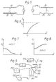
- the first controller to be described which is designed to convert incident radiation of arbitrary elliptical polarisation into linear polarisation of known azimuth, or vice versa, comprises a stack of two liquid crystal cells 1, 3, these cells being arranged with their slow axes 5, 7, i.e. polarisation direction of the extraordinary ray within the cell, set at 45 o .
- each cell 1, 3 comprises a sandwich comprising a nematic liquid crystal film 9 confined between two plates 11, 13 of glass, the nematic film being typically between 5 ⁇ m and 10 ⁇ m thick.
- the plates 11, 13 are spaced from each other and sealed by a seal 15 incorporating spacer particles of glass or carbon fibres.
- the two plates 11, 13 each carry on their inner surface a respective thin transparent electrode 16, 17, generally formed from indium tin oxide, respective barrier layers of SiO2 19, 21 being interposed between each plate 11, 13 and the corresponding electrode 16, 17 so as to prevent migration of sodium ions from the glass plates into the liquid crystal film 9.
- respective thin alignment layers 23, 25 On the inner surface of each electrode 16, 17 there are formed respective thin alignment layers 23, 25. These layers cause the optic axis of the liquid crystal to align parallel to, or tilted at a small angle to, the plates 11, 13, i.e. they cause the crystal to adopt a homogenous alignment. The tilted arrangement is preferred since it resolves a degeneracy which might otherwise cause formation of domains when an electric field is applied across the cell.
- Suitable alignment layers include rubbed polymer surfaces which impart a tilt of typically 2°, or obliquely evaporated silicon monoxide films which impart either zero tilt or a tilt of, typically, about 30°, according to the geometry of the evaporation.
- the cell is assembled with the alignment directions, 10, antiparallel so that in the absence of an applied voltage the optic axis 12 in the bulk of the liquid 9 adopts uniform configuration throughout the cell. If the liquid crystal has a positive dielectric anisotropy, on application of an AC voltage to the cell the configuration of the optic axis will become distorted as shown in Figure 3. As a result, the phase retardation between ordinary and extraordinary rays transmitted normally through the birefringent cell will vary with RMS applied voltage V as shown in Figure 4.
- a beam of incident light 101 enters the cell 1 with arbitrary polarisation, shown in Figure 1 by the elliptical representation 103.
- the voltage applied to the cell 1 via the electrodes 16, 17 is chosen so that both the azimuth and ellipticity of the polarisation are changed, with the principal axes of the ellipse, 105, parallel and perpendicular to the slow axis 5 of the cell 1 as represented by the elliptical representation 105.
- the voltage on the second cell 3 is then set so that the light emerging from the stack is linearly polarised as shown in the representation 107.
- the electronic feedback circuitry required for this purpose is not shown but will be evident to those skilled in the art of polarisation controllers.
- phase retardations required of the cells 1, 3 are given below:
- Premultiplying phase factors are never given explicity. When, in the course of a calculation, the phase factor changes this is denoted by use of an equivalence symbol, ⁇ , in place of the equals sign.
- Linearly polarised light is incident with its plane of polarisation inclined at 45° to the slow axis 5 of the first cell 1, thereby achieving conversion to elliptical polarisation with principal axes parallel and perpendicular to the slow axis 7 of the second cell 3. Conversion to the desired azimuth and ellipticity is then completed by the second cell 3.
- the polariser described herebefore by way of example incorporates two homogeneously aligned nematic liquid crystal cells, the polariser may equally include liquid crystal cells of alternative alignments.
- the cells 1, 3 may alternatively incorporate a nematic liquid crystal film having a homeotropic alignment.
- both plates 11, 13 will bear alignment layers of a type which cause the optic axis of the liquid crystal to align perpendicular to, or tilted at a small angle to the perpendicular to, the plate.
- the latter arrangement is preferred since it resolves a degeneracy which might otherwise cause formation of domains when an electric field is applied across the cell.
- Preferred alignment layers include surfactants (which impart perpendicular alignment) or surfactants applied over obliquely evaporated silicon monoxide films of the type which alone would give 30° tilt (the surfactants thus imparting a tilt to perpendicular alignment).
- each cell is assembled with the alignment directions 30 antiparallel so that in the absence of an applied voltage the optic axis in the bulk of the liquid 32 adopts a uniform configuration throughout the cell.
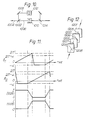
- the configuration of the optic axis becomes distorted as shown in Figure 5.
- the phase retardation between ordinary and extraordinary rays transmitted normally through the birefringent cell varies with RMS applied voltage V as shown in Figure 6.
- a further alternative alignment for the cells 1, 3 is a hybrid alignment in which one plate bears an alignment layer of homogeneous type while the other bears a layer of homeotropic type.
- the liquid crystal may have either positive or negative dielectric anisotropy.
- the phase retardation between ordinary and extraordinary rays transmitted normally through the birefringent cell will decrease in the former case and increase in the later case, as shown in Figures 7 and 8 respectively.
- a further alternative alignment for the cells 1, 3 is a hybrid alignment in which one plate bears an alignment layer of homogeneous type in which the optic axis makes a particular angle with the plate while the other bears an alignment layer of homogeneous type in which the optic axis makes a different angle with the plate, the cell being assembled with the alignment directions antiparallel.
- each cell 1, 3 within the above controller may include a liquid crystal having any one of the above alignments, i.e. homogeneous, homeotropic or hybrid.
- the two cells, 1, 3 may be separated by a single glass plate with electrode and alignment layers applied to both sides, or may be fabricated from two plates joined with optical cement.
- threshold voltages V o shown in Figures 4 and 6 typically lie in the range one to three volts.
- the operating voltage of a controller in accordance with the invention will be typically 2 to 4 volts.
- each liquid crystal layer in a controller in accordance with the invention will be short, typically a few ⁇ m. With proper attention to antireflection coatings insertion losses will therefore be very small, typically fractions of a dB per liquid crystal layer, and the power required to operate the controller will be in the microwatt range.
- the thickness and relative refractive indices of layers used in the construction of the controller may be chosen such that interference effects serve to reduce insertion losses. Alternatively, interference effects may be reduced or eliminated by use of layers of wedged shape.
- liquid crystal cells described above by way of example incorporate liquid crystal films of between 5 ⁇ m and 10 ⁇ m thickness, thinner films may be used with appropriate materials in order to obtain particularly fast response time.
- polarisation controllers in accordance with the first aspect of the invention may be free space devices, or they may be fabricated integral with source or detector devices, or may be incorporated into integrated optical devices.
- an arbitrary to linear controller followed by a linear to arbitrary controller can function as an arbitrary to arbitrary controller, provided that the output polarisation of the arbitrary to linear controller coincides with the input polarisation of the linear to arbitrary controller.
- a controller needs a total of 4 liquid crystal cells of any combination of homogeneous, homeotropic and hybrid alignments.
- the second controller to be described functions as an arbitrary to arbitrary controller using only three cells 90, 92, 94 as shown in Figure 9, each cell being of the form as described in relation to the first controller.
- the beam of light 912 with arbitrary polarisation 914 is converted by the first cell 90 into a beam with elliptical polarisation 916 with principal axes parallel and perpendicular to the slow axis 96 of the cell 90.
- the second and third cells 92 and 94 then act as a known-azimuth to arbitrary convertor as described above in relation to the first controller.
- the cell 92 having its slow axis 98 inclined at ⁇ 45° to the axis 96, changes the ellipticity but not the azimuth of the incident radiation 912 and the third device 94, the slow axis 910 of which is either parallel or perpendicular to the axis 96 the former being shown in Figure 9, completes the conversion to the desired output polarisation 920.
- the third controller comprises a routing device 1002 effective to route an incoming beam 1004 the polarisation of which it is sought to control partly or entirely into two alternative paths 1006, 1008.
- Each path 1006, 1008 contains a respective stack of liquid crystal cells 1010, 1012 each of the general form described herebefore in relation to either the first or second controller.
- a recombining device 1014 effective to combine the two paths 1006, 1008 is also provided.
- ⁇ 1 represents the phase retardation produced by a particular cell in the stack 1010
- ⁇ 2 represents the phase retardation produced by the corresponding cell in the stack 1012
- the routing device in use of the controller the routing device is initially arranged such that the incoming light is routed exclusively along the path 1006, i.e. the intensity I (1008) of the light transmitted along the path 1008 is zero as indicated in Figure 11.
- the phase retardation produced by the cell in the stack 1010 is arranged to increase until it approaches within an amount ⁇ of a convenient unit which here is taken to be 2 ⁇ , the cell in the stack 1012 being set such that it imposes a phase retardation of - ⁇ , i.e. the same modulo 2 ⁇ .
- the routing device 1002 is now arranged to fade the beam 1004 out of the path 1006 and into the path 1008, the overall intensity I (1008) plus I (1006) of course being a constant.
- routing and fading devices may themselves introduce changes in the polarisation of the beam. If these changes are unsymmetrical between branches 1 and 2 then the simple relationship between ⁇ 1 and ⁇ 2 shown in Figure 11 will be modified.
- the fourth controller comprises four cells 1201, 1202, 1203, 1204 in which the slow axes 1205, 1207 of the first and third cells are parallel and perpendicular and the slow axes of the second and fourth cells 1206, 1208 are oriented at ⁇ 45° to the axis of the first cell.
- Algorithms for the control of such a controller will be readily understood by those skilled in the art from the algorithms published for fibre squeezer devices.
- the cells are controlled by electric fields applied thereto, alternatively the cells may be magnetically controlled.
Landscapes
- Physics & Mathematics (AREA)
- Nonlinear Science (AREA)
- General Physics & Mathematics (AREA)
- Optics & Photonics (AREA)
- Mathematical Physics (AREA)
- Chemical & Material Sciences (AREA)
- Crystallography & Structural Chemistry (AREA)
- Liquid Crystal (AREA)
Claims (7)
- Polarisationsregler, aufweisend einen Stapel von zumindest zwei elektrooptischen Modulatoren (1,3), die derart angeordnet sind, daß auf den Stapel auftreffende Strahlung aufeinanderfolgend durch die Modulatoren treten wird; und eine Einrichtung (16,17), die über die Modulatoren synchronisierte Felder legt, um so die Phasenverzögerung der durch jeden Modulator hindurchgelassenen Strahlung um einen ausgewählten Betrag zu ändern, wobei die optischen Achsen der Modulatoren bezüglich einander derart orientiert sind, daß die Polarisation von durch den Regler hinduchgelassener Strahlung von einem ersten Polarisationszustand, in dem die Strahlung auf den Regler auftritt, in einen zweiten Polarisationszustand geändert wird, in dem die Strahlung den Regler verläßt, wobei die Einrichtung zum Anlegen synchronisierter Felder eine Rückkopplungseinrichtung umfaßt, die so wirksam ist, daß sie die Werte dieser Felder in Abhängigkeit vom zweiten Zustand ändert, dadurch gekennzeichnet, daß die elektrooptischen Modulatoren nematische Flüssigkristallzellen sind.
- Regler nach Anspruch 1, bei dem einer der Zustände eine beliebige elliptische Polarisation ist und der andere Zustand eine lineare Polarisation bekannten Azimuts ist, dadurch gekennzeichnet, daß die elektrooptischen Modulatoren (1,3) zwei solcher Flüssigkristallzellen umfassen, die so angeordnet sind, daß ihre langsamen Achsen (5,7) bezüglich einander auf im wesentlichen 45° eingestellt sind.
- Regler nach Anspruch 1, bei dem der erste und zweite Zustand beide beliebige elliptische Polarisationen sind, dadurch gekennzeichnet, daß die elektrooptischen Modulatoren (90,92,94) drei Flüssigkristallzellen umfassen, wobei die langsamen Achsen (96,910) der ersten und letzten Flüssigkristallzelle (90,94) entweder senkrecht oder parallel zueinander sind, die langsame Achse (98) der dazwischenliegenden Flüssigkristallzelle (92) unter einem Winkel von im wesentlichen ±45° zur langsamen Achse der ersten Zelle geneigt ist.
- Regler nach Anspruch 1, bei dem der erste Zustand eine kontinuierlich variierende, beliebige Polarisation ist, gekennzeichnet durch einen Stapel von vier solchen nematischen Flüssigkristallzellen (1201-1204), wobei die langsamen Achsen (1205,1207) der ersten und dritten Zelle innerhalb des Stapels entweder parallel oder senkrecht zueinander sind und die langsamen Achsen (1206, 1208) der zweiten und vierten Zelle unter einem Winkel von im wesentlichen ±45° zur langsamen Achse der ersten Zelle geneigt sind.
- Regler nach einem vorhergehenden Anspruch, dadurch gekennzeichnet, daß jedes Feld ein elektrisches Feld ist.
- Regler nach einem vorhergehenden Anspruch, dadurch gekennzeichnet, daß der Phasenverzögerungsbereich jeder Zelle zumindest 3π rad beträgt.
- Polarisationsregler, aufweisend zwei Stapel (1010,1012) von zumindest zwei nematische Flüssigkristallzellen, die derart angeordnet sind, daß auf jeden Stapel auftreffende Strahlung aufeinanderfolgend durch jede Zelle im Stapel treten wird, wobei die Stapel zwei alternative optische Wege (1006,1008) darstellen; eine Einrichtung, die synchronisierte Felder über die Zellen legt und so wirksam ist, daß sie die Phasenverzögerung der durch jede Zelle hindurchgelassenen Strahlung um einen ausgewählten variablen Betrag derart ändert, daß die Phasenverzögerung entlang jedes Weges periodisch variiert, wobei die optischen Achsen der Zellen bezüglich einander derart orientiert sind, daß die Polarisation von durch den Regler hindurchgelassener Strahlung aus einem kontinuierlich variierenden ersten Polarisationszustand, in dem die Strahlung auf den Regler auftrifft, in einen zweiten Polarisationszustand geändert wird, in dem die Strahlung den Regler verläßt, wobei einer der Zustände eine erste beliebige Polarisation ist und der andere der Zustände eine vorselektierte feste Polarisation oder eine zweite beliebige Polarisation ist; und eine Einrichtung zur periodischen Variation der sich entlang jedes Weges ausbreitenden Anteilsproportionen der auftreffenden Strahlung.
Applications Claiming Priority (2)
| Application Number | Priority Date | Filing Date | Title |
|---|---|---|---|
| GB8703795 | 1987-02-18 | ||
| GB878703795A GB8703795D0 (en) | 1987-02-18 | 1987-02-18 | Polarisation controller |
Publications (2)
| Publication Number | Publication Date |
|---|---|
| EP0302091A1 EP0302091A1 (de) | 1989-02-08 |
| EP0302091B1 true EP0302091B1 (de) | 1993-06-16 |
Family
ID=10612525
Family Applications (1)
| Application Number | Title | Priority Date | Filing Date |
|---|---|---|---|
| EP88901626A Expired - Lifetime EP0302091B1 (de) | 1987-02-18 | 1988-02-18 | Polarisationsregler |
Country Status (6)
| Country | Link |
|---|---|
| US (1) | US5005952A (de) |
| EP (1) | EP0302091B1 (de) |
| JP (1) | JPH01502462A (de) |
| DE (1) | DE3881780T2 (de) |
| GB (2) | GB8703795D0 (de) |
| WO (1) | WO1988006303A1 (de) |
Families Citing this family (29)
| Publication number | Priority date | Publication date | Assignee | Title |
|---|---|---|---|---|
| GB2255193B (en) * | 1991-04-24 | 1994-10-12 | Marconi Gec Ltd | Optical device |
| EP0528542B1 (de) * | 1991-07-19 | 1998-09-16 | SHARP Corporation | Optisches Modulationselement und Vorrichtungen mit einem solchen Element |
| US5260719A (en) * | 1992-01-24 | 1993-11-09 | Polaroid Corporation | Laminar electrooptic assembly for modulator and printer |
| US5347382A (en) * | 1992-04-23 | 1994-09-13 | Rumbaugh Scott H | Liquid crystal cell retarder with driving beyond retardance value and two cells for high speed |
| US6693696B1 (en) | 1992-06-30 | 2004-02-17 | Semiconductor Energy Laboratory Co., Ltd. | Electro-optical device |
| JPH0618887A (ja) * | 1992-06-30 | 1994-01-28 | Semiconductor Energy Lab Co Ltd | 液晶電気光学装置 |
| US5463312A (en) * | 1994-03-03 | 1995-10-31 | Minnesota Mining And Manufacturing Company | Faraday-effect sensing coil with stable birefringence |
| WO1996007951A1 (en) * | 1994-09-08 | 1996-03-14 | British Telecommunications Plc | Polarisation modulation |
| US6437762B1 (en) | 1995-01-11 | 2002-08-20 | William A. Birdwell | Dynamic diffractive optical transform |
| US5986815A (en) * | 1998-05-15 | 1999-11-16 | Optical Coating Laboratory, Inc. | Systems, methods and apparatus for improving the contrast ratio in reflective imaging systems utilizing color splitters |
| DE19833312A1 (de) * | 1998-07-24 | 2000-02-03 | Deutsche Telekom Ag | Vorrichtung zum Regeln der Polarisation einfallenden Lichtes und Polarisations-Stellvorrichtung für eine solche Regelvorrichtung |
| DE19833330C2 (de) * | 1998-07-24 | 2001-03-15 | Deutsche Telekom Ag | Quantenkryptographiesystem zur gesicherten Übertragung zufälliger Schlüssel unter Verwendung des Polarisationsstellverfahrens |
| NO321724B1 (no) | 1999-06-15 | 2006-06-26 | Optoplan As | Framgangsmate og anordning for malinger av de ortogonalt polariserte Bragg-bolgelengdene fra fiber-Bragg-gitter |
| US6398364B1 (en) | 1999-10-06 | 2002-06-04 | Optical Coating Laboratory, Inc. | Off-axis image projection display system |
| US20020015547A1 (en) * | 2000-01-07 | 2002-02-07 | Patel Jay S. | Compact multi-channel polarization mode dispersion compensator |
| US6686984B1 (en) * | 2000-02-29 | 2004-02-03 | Agilent Technologies, Inc. | Polarization control device |
| US6404537B1 (en) | 2000-03-06 | 2002-06-11 | Corning Applied Technologies Corporation | Polarization transformer |
| US6717706B2 (en) * | 2000-08-31 | 2004-04-06 | Cambridge Research And Instrumentation, Inc. | State of polarization detector |
| US6373614B1 (en) | 2000-08-31 | 2002-04-16 | Cambridge Research Instrumentation Inc. | High performance polarization controller and polarization sensor |
| US6526187B1 (en) * | 2001-05-17 | 2003-02-25 | Optronx, Inc. | Polarization control apparatus and associated method |
| EP1412808B1 (de) * | 2001-08-03 | 2013-07-10 | Google, Inc. | Polarisationsregelung |
| US7085052B2 (en) * | 2002-03-14 | 2006-08-01 | Optellios, Inc. | Over-parameterized polarization controller |
| US6888659B2 (en) | 2002-12-10 | 2005-05-03 | Jds Uniphase Inc. | Polarization controller |
| US7035009B1 (en) | 2003-11-26 | 2006-04-25 | Coadna Photonics, Inc. | Apparatus and method for controlling polarization in an optical communications medium |
| US7315665B1 (en) | 2004-02-10 | 2008-01-01 | Meadowlark Optics, Inc. | Liquid-crystal planar-waveguide apparatus and method for fast control of polarization and other properties of light |
| US20060262396A1 (en) * | 2005-05-19 | 2006-11-23 | Smith Irl W | Optical diplexer with liquid crystal tunable waveplate |
| US7880863B2 (en) * | 2008-01-22 | 2011-02-01 | Infineon Technologies Ag | Lithography system with illumination monitor |
| JP2011186331A (ja) * | 2010-03-10 | 2011-09-22 | Seiko Epson Corp | 液晶装置および液晶メガネ |
| JP6817623B2 (ja) * | 2016-11-28 | 2021-01-20 | 公立大学法人兵庫県立大学 | 偏光制御装置および偏光制御方法 |
Family Cites Families (18)
| Publication number | Priority date | Publication date | Assignee | Title |
|---|---|---|---|---|
| NL6713762A (de) * | 1967-10-10 | 1969-04-14 | ||
| SE358740B (de) * | 1967-10-10 | 1973-08-06 | Philips Nv | |
| NL6715244A (de) * | 1967-11-09 | 1969-05-13 | ||
| DE1806729A1 (de) * | 1967-11-09 | 1969-06-26 | Philips Nv | Vorrichtung zur Umwandlung linear Polarisierter Strahlung mit einer beliebigen Polarisationsebene in linear polarisierte Strahlung,deren Polarisationsebene sich mit konstanter Winkelgeschwindigkeit dreht |
| NL6716351A (de) * | 1967-12-01 | 1969-06-03 | ||
| NL7005295A (de) * | 1970-04-13 | 1971-10-15 | ||
| US3753608A (en) * | 1971-04-15 | 1973-08-21 | Honeywell Inc | Optical polarization spot size changing devices |
| US3956626A (en) * | 1973-06-14 | 1976-05-11 | Mcdonnell Douglas Corporation | Pulse quaternary communication means |
| US3890628A (en) * | 1973-10-23 | 1975-06-17 | Motorola Inc | Liquid crystal light control device and circuit |
| US4394069A (en) * | 1979-06-05 | 1983-07-19 | Beckman Instruments, Inc. | Liquid crystal tuned birefringent filter |
| US4443065A (en) * | 1980-12-09 | 1984-04-17 | Sharp Kabushiki Kaisha | Interference color compensation double layered twisted nematic display |
| US4408839A (en) * | 1981-04-01 | 1983-10-11 | Hughes Aircraft Company | Twisted nematic liquid light valve with birefringence compensation |
| US4466702A (en) * | 1981-04-01 | 1984-08-21 | Hughes Aircraft Company | Liquid crystal light valve with birefringence compensation |
| JPS5834429A (ja) * | 1981-08-24 | 1983-02-28 | Seiko Epson Corp | 偏光素子 |
| JP2725765B2 (ja) * | 1983-04-18 | 1998-03-11 | 富士通株式会社 | 光スイッチ用偏光換装置 |
| DE3671986D1 (de) * | 1985-03-18 | 1990-07-19 | Nec Corp | Vorrichtung zur regelung der polarisation mit einem strahlteiler. |
| FR2584521B1 (fr) * | 1985-07-02 | 1989-10-06 | Renault | Dispositif d'affichage electro-optique a cristal liquide |
| GB2184251B (en) * | 1985-12-13 | 1990-02-07 | Stc Plc | Optical state of polarisation modulator |
-
1987
- 1987-02-18 GB GB878703795A patent/GB8703795D0/en active Pending
-
1988
- 1988-02-18 JP JP63501665A patent/JPH01502462A/ja active Pending
- 1988-02-18 US US07/264,952 patent/US5005952A/en not_active Expired - Lifetime
- 1988-02-18 DE DE88901626T patent/DE3881780T2/de not_active Expired - Fee Related
- 1988-02-18 EP EP88901626A patent/EP0302091B1/de not_active Expired - Lifetime
- 1988-02-18 WO PCT/GB1988/000105 patent/WO1988006303A1/en not_active Ceased
- 1988-02-18 GB GB8803783A patent/GB2202643B/en not_active Expired - Lifetime
Non-Patent Citations (1)
| Title |
|---|
| PATENT ABSTRACTS OF JAPAN, vol. 7, no. 113 (P-197)(1258), 18 May 1983, & JP-A-5834429 (SUWA SEIKOSHA KK), 28 February 1983. * |
Also Published As
| Publication number | Publication date |
|---|---|
| DE3881780D1 (de) | 1993-07-22 |
| WO1988006303A1 (en) | 1988-08-25 |
| GB2202643A (en) | 1988-09-28 |
| US5005952A (en) | 1991-04-09 |
| DE3881780T2 (de) | 1993-10-07 |
| GB8803783D0 (en) | 1988-03-16 |
| EP0302091A1 (de) | 1989-02-08 |
| JPH01502462A (ja) | 1989-08-24 |
| GB8703795D0 (en) | 1987-03-25 |
| GB2202643B (en) | 1991-03-27 |
Similar Documents
| Publication | Publication Date | Title |
|---|---|---|
| EP0302091B1 (de) | Polarisationsregler | |
| US3272988A (en) | Polarization modulation system for transmitting and receiving two independent signals over a single electromagnetic carrier | |
| EP0680619B1 (de) | Ein polarisationsunabhaengiges optisches schaltelement/daempfungsglied | |
| US3876287A (en) | Birefringent liquid crystal structure | |
| EP0054411B1 (de) | Optische Anordnung zur optischen Kopplung von Lichtfasern | |
| US5187603A (en) | High contrast light shutter system | |
| EP0814361B1 (de) | Optische Vorrichtung | |
| US6490076B2 (en) | Optical phased array for depolarized optical beam control | |
| US4439014A (en) | Low voltage electro-optic modulator | |
| US6931165B2 (en) | Variable polarization plane rotator and optical device using same | |
| EP0075015A4 (de) | Flüssigkristallichtventil mit doppelbrechungskompensation. | |
| KR20010074479A (ko) | 고속 전기광학 변조기 | |
| EP0699938A2 (de) | Flüssigkristallanzeige | |
| Sterzer et al. | Cuprous chloride light modulators | |
| JPS6378124A (ja) | 偏極調整装置 | |
| CN102096206B (zh) | 电光可变光衰减器 | |
| US4522468A (en) | Information display device having a liquid crystal cell | |
| US7019724B2 (en) | Liquid crystal optical switch | |
| US6765635B1 (en) | Apparatus and method for achromatic liquid crystal electro-optic modulation | |
| EP0463723A2 (de) | Lichtventilvorrichtung mit hohem Kontrast | |
| JP3149120B2 (ja) | 可変波長光フィルタ | |
| US3440424A (en) | Optical system for transmitting and receiving two independent signals over a single electromagnetic carrier wherein the rotational orientation of the receiver is independent of the angular position of the transmitter | |
| US6686984B1 (en) | Polarization control device | |
| US3957340A (en) | Electrooptical amplitude modulator | |
| Ohtera et al. | Liquid crystal rotatable waveplates |
Legal Events
| Date | Code | Title | Description |
|---|---|---|---|
| PUAI | Public reference made under article 153(3) epc to a published international application that has entered the european phase |
Free format text: ORIGINAL CODE: 0009012 |
|
| 17P | Request for examination filed |
Effective date: 19881017 |
|
| AK | Designated contracting states |
Kind code of ref document: A1 Designated state(s): BE CH DE FR IT LI NL SE |
|
| RBV | Designated contracting states (corrected) |
Designated state(s): CH DE FR IT LI NL SE |
|
| 17Q | First examination report despatched |
Effective date: 19910507 |
|
| GRAA | (expected) grant |
Free format text: ORIGINAL CODE: 0009210 |
|
| AK | Designated contracting states |
Kind code of ref document: B1 Designated state(s): CH DE FR IT LI NL SE |
|
| PG25 | Lapsed in a contracting state [announced via postgrant information from national office to epo] |
Ref country code: IT Free format text: LAPSE BECAUSE OF FAILURE TO SUBMIT A TRANSLATION OF THE DESCRIPTION OR TO PAY THE FEE WITHIN THE PRE;WARNING: LAPSES OF ITALIAN PATENTS WITH EFFECTIVE DATE BEFORE 2007 MAY HAVE OCCURRED AT ANY TIME BEFORE 2007. THE CORRECT EFFECTIVE DATE MAY BE DIFFERENT FROM THE ONE RECORDED.SCRIBED TIME-LIMIT Effective date: 19930616 Ref country code: LI Effective date: 19930616 Ref country code: CH Effective date: 19930616 |
|
| ET | Fr: translation filed | ||
| REF | Corresponds to: |
Ref document number: 3881780 Country of ref document: DE Date of ref document: 19930722 |
|
| REG | Reference to a national code |
Ref country code: CH Ref legal event code: PL |
|
| PLBE | No opposition filed within time limit |
Free format text: ORIGINAL CODE: 0009261 |
|
| STAA | Information on the status of an ep patent application or granted ep patent |
Free format text: STATUS: NO OPPOSITION FILED WITHIN TIME LIMIT |
|
| 26N | No opposition filed | ||
| EAL | Se: european patent in force in sweden |
Ref document number: 88901626.7 |
|
| PGFP | Annual fee paid to national office [announced via postgrant information from national office to epo] |
Ref country code: SE Payment date: 19990204 Year of fee payment: 12 |
|
| PGFP | Annual fee paid to national office [announced via postgrant information from national office to epo] |
Ref country code: FR Payment date: 19990209 Year of fee payment: 12 |
|
| PGFP | Annual fee paid to national office [announced via postgrant information from national office to epo] |
Ref country code: NL Payment date: 19990224 Year of fee payment: 12 |
|
| PGFP | Annual fee paid to national office [announced via postgrant information from national office to epo] |
Ref country code: DE Payment date: 19990301 Year of fee payment: 12 |
|
| PG25 | Lapsed in a contracting state [announced via postgrant information from national office to epo] |
Ref country code: SE Free format text: LAPSE BECAUSE OF NON-PAYMENT OF DUE FEES Effective date: 20000219 |
|
| PG25 | Lapsed in a contracting state [announced via postgrant information from national office to epo] |
Ref country code: NL Free format text: LAPSE BECAUSE OF NON-PAYMENT OF DUE FEES Effective date: 20000901 |
|
| EUG | Se: european patent has lapsed |
Ref document number: 88901626.7 |
|
| PG25 | Lapsed in a contracting state [announced via postgrant information from national office to epo] |
Ref country code: FR Free format text: LAPSE BECAUSE OF NON-PAYMENT OF DUE FEES Effective date: 20001031 |
|
| NLV4 | Nl: lapsed or anulled due to non-payment of the annual fee |
Effective date: 20000901 |
|
| PG25 | Lapsed in a contracting state [announced via postgrant information from national office to epo] |
Ref country code: DE Free format text: LAPSE BECAUSE OF NON-PAYMENT OF DUE FEES Effective date: 20001201 |
|
| REG | Reference to a national code |
Ref country code: FR Ref legal event code: ST |