EP0301931A2 - Verfahren und Einrichtung zur Feststellung des Verschleisses eines rotierenden Schneidewerkzeuges - Google Patents
Verfahren und Einrichtung zur Feststellung des Verschleisses eines rotierenden Schneidewerkzeuges Download PDFInfo
- Publication number
- EP0301931A2 EP0301931A2 EP88401770A EP88401770A EP0301931A2 EP 0301931 A2 EP0301931 A2 EP 0301931A2 EP 88401770 A EP88401770 A EP 88401770A EP 88401770 A EP88401770 A EP 88401770A EP 0301931 A2 EP0301931 A2 EP 0301931A2
- Authority
- EP
- European Patent Office
- Prior art keywords
- tool
- wear
- rotation
- values
- signal
- Prior art date
- Legal status (The legal status is an assumption and is not a legal conclusion. Google has not performed a legal analysis and makes no representation as to the accuracy of the status listed.)
- Withdrawn
Links
Images

Classifications
-
- G—PHYSICS
- G05—CONTROLLING; REGULATING
- G05B—CONTROL OR REGULATING SYSTEMS IN GENERAL; FUNCTIONAL ELEMENTS OF SUCH SYSTEMS; MONITORING OR TESTING ARRANGEMENTS FOR SUCH SYSTEMS OR ELEMENTS
- G05B19/00—Programme-control systems
- G05B19/02—Programme-control systems electric
- G05B19/18—Numerical control [NC], i.e. automatically operating machines, in particular machine tools, e.g. in a manufacturing environment, so as to execute positioning, movement or co-ordinated operations by means of programme data in numerical form
- G05B19/406—Numerical control [NC], i.e. automatically operating machines, in particular machine tools, e.g. in a manufacturing environment, so as to execute positioning, movement or co-ordinated operations by means of programme data in numerical form characterised by monitoring or safety
- G05B19/4065—Monitoring tool breakage, life or condition
-
- G—PHYSICS
- G05—CONTROLLING; REGULATING
- G05B—CONTROL OR REGULATING SYSTEMS IN GENERAL; FUNCTIONAL ELEMENTS OF SUCH SYSTEMS; MONITORING OR TESTING ARRANGEMENTS FOR SUCH SYSTEMS OR ELEMENTS
- G05B2219/00—Program-control systems
- G05B2219/30—Nc systems
- G05B2219/37—Measurements
- G05B2219/37256—Wear, tool wear
-
- G—PHYSICS
- G05—CONTROLLING; REGULATING
- G05B—CONTROL OR REGULATING SYSTEMS IN GENERAL; FUNCTIONAL ELEMENTS OF SUCH SYSTEMS; MONITORING OR TESTING ARRANGEMENTS FOR SUCH SYSTEMS OR ELEMENTS
- G05B2219/00—Program-control systems
- G05B2219/30—Nc systems
- G05B2219/37—Measurements
- G05B2219/37347—Speed, velocity
-
- G—PHYSICS
- G05—CONTROLLING; REGULATING
- G05B—CONTROL OR REGULATING SYSTEMS IN GENERAL; FUNCTIONAL ELEMENTS OF SUCH SYSTEMS; MONITORING OR TESTING ARRANGEMENTS FOR SUCH SYSTEMS OR ELEMENTS
- G05B2219/00—Program-control systems
- G05B2219/30—Nc systems
- G05B2219/37—Measurements
- G05B2219/37536—Rate of change, derivative
Definitions
- the present invention relates to a method and a device for detecting wear of a rotary cutting tool.
- US Pat. No. 4,471,444 already discloses a wear detection device in which the vibrations produced are measured using an accelerometer and the signal given by said accelerometer is analyzed. The information is analog. It is therefore necessary to go through a digitization step in order to exploit the signal from a microprocessor.
- the invention proposes a method and a device which analyze the variations in instantaneous speed of the rotary cutting tool. It also provides a docking detector that can be used in milling, drilling, boring ...
- the method according to the invention is characterized in that it consists in measuring the speed of rotation of the tool, in calculating values representative of the instantaneous speed several times per revolution, in storing these values representative of the instantaneous speed over several turns and processing these values to provide a factor representative of tool wear.
- the method consists in counting the time intervals between the pulses given by a sensor delivering a pulse at each rotation by a determined angle.
- the method consists in determining from the signal representative of the values of the instantaneous speed the harmonics corresponding to the number of teeth of the tool and to at least a multiple of this number and in determining an identification factor d wear as a function of the quadratic sum of these harmonics.
- the operation thus carried out is a filtering of the signal.
- the device according to the invention is characterized in that it comprises a rotary sensor linked in rotation to the cutting tool and delivering a pulse for each rotation by a determined angle to a unit for calculating and processing the signal at micro processor.
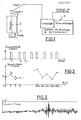
- the device is used to detect the wear of a rotary cutting tool 1 rotating around an axis 2.
- the speed of rotation of the tool is measured by a tachometer sensor 3 delivering its signal to a calculation and processing unit. of the microprocessor signal 4.
- the tool is a cutter mounted on a spindle.
- the sensor 3 delivers a pulse at each rotation by a determined angle. As an indication, it only delivers pulses as shown in FIG. 2, namely 360 pulses per revolution, ie one pulse each time the tool turns one degree.
- the electronic system 4 timed the time interval between each pulse.
- Each measured time interval will be stored in memory and a series of values is thus obtained which represents a sampled signal.
- This signal is not the speed of the tool but its inverse because it expresses times per unit of angle, represented on the lower part of figure 2
- the signal is not sampled in time but in angle. It is directly synchronized with the rotation of the tool and the calculation of the spectral lines is simplified.
- FIG. 3 shows the reverse speed signal.
- the signal processing method is given in FIG. 4 when the variations in speed due to the cut are covered by other variations. The variations in speed due to cutting are drowned out in the other variations.
- the calculation unit 4 times the time intervals separating each top provided by the sensor and stores the different intervals over at least one revolution of the tool.
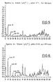
- the calculation unit calculates from the inverse speed signal the harmonics correspond to the number of teeth of the tool and to at least a multiple of this number of teeth of the tool and performs an averaging of these values . As an indication in the process, the first four multiples are taken.
- the calculation unit determines a wear identification factor equal to the quadratic sum of these first harmonics divided by two. This wear identification value is the variance of the signal reconstructed from the harmonic lines.
- This factor which reflects the state of wear is displayed or compared to a limit threshold to give or not the alert.
- Figures 5 and 6 show the first harmonics of the reverse speed signal on the new tool ( Figure 5) and on the used tool ( Figure 6).
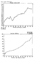
- FIGS. 7 and 8 show the good correlation between the wear identification factor and the wear of the tool evaluated by conventional means.
Landscapes
- Engineering & Computer Science (AREA)
- Human Computer Interaction (AREA)
- Manufacturing & Machinery (AREA)
- Physics & Mathematics (AREA)
- General Physics & Mathematics (AREA)
- Automation & Control Theory (AREA)
- Machine Tool Sensing Apparatuses (AREA)
- Length Measuring Devices With Unspecified Measuring Means (AREA)
Applications Claiming Priority (2)
| Application Number | Priority Date | Filing Date | Title |
|---|---|---|---|
| FR8709610A FR2617747B1 (fr) | 1987-07-07 | 1987-07-07 | Procede et dispositif de detection d'usure d'un outil de coupe rotatif |
| FR8709610 | 1987-07-07 |
Publications (2)
| Publication Number | Publication Date |
|---|---|
| EP0301931A2 true EP0301931A2 (de) | 1989-02-01 |
| EP0301931A3 EP0301931A3 (de) | 1989-02-15 |
Family
ID=9352945
Family Applications (1)
| Application Number | Title | Priority Date | Filing Date |
|---|---|---|---|
| EP88401770A Withdrawn EP0301931A3 (de) | 1987-07-07 | 1988-07-06 | Verfahren und Einrichtung zur Feststellung des Verschleisses eines rotierenden Schneidewerkzeuges |
Country Status (2)
| Country | Link |
|---|---|
| EP (1) | EP0301931A3 (de) |
| FR (1) | FR2617747B1 (de) |
Family Cites Families (2)
| Publication number | Priority date | Publication date | Assignee | Title |
|---|---|---|---|---|
| US4228514A (en) * | 1979-04-16 | 1980-10-14 | Bell Telephone Laboratories, Incorporated | Method and system for determining the wear of a drill bit in real time |
| US4471444A (en) * | 1982-04-02 | 1984-09-11 | The United States Of America As Represented By The Secretary Of Commerce | Rotating tool wear monitoring apparatus |
-
1987
- 1987-07-07 FR FR8709610A patent/FR2617747B1/fr not_active Expired
-
1988
- 1988-07-06 EP EP88401770A patent/EP0301931A3/de not_active Withdrawn
Also Published As
| Publication number | Publication date |
|---|---|
| FR2617747B1 (fr) | 1989-12-15 |
| EP0301931A3 (de) | 1989-02-15 |
| FR2617747A1 (fr) | 1989-01-13 |
Similar Documents
| Publication | Publication Date | Title |
|---|---|---|
| FR2644717A1 (fr) | Procede et dispositif de detection de plusieurs niveaux de rupture d'outil utilisant differents types de capteurs | |
| Lamraoui et al. | Cyclostationarity approach for monitoring chatter and tool wear in high speed milling | |
| US4129276A (en) | Technique for the detection of flat wheels on railroad cars by acoustical measuring means | |
| CA1329848C (en) | Nonsynchronous turbine blade vibration monitoring system | |
| EP2422178B1 (de) | Verfahren zum detektieren eines strukturdefekts in einer mechanischen baugruppe mit einem drehglied | |
| FR2532770A1 (fr) | Detecteur d'outil use et procede de detection de l'etat d'un outil d'une machine automatisee | |
| JPS58500605A (ja) | 周期的機械加工をする工作機械の工具の状況を監視する方法および装置 | |
| FR2551209A1 (fr) | Procede et appareil de mesure de desequilibre | |
| FR2470386A1 (fr) | Capteur de vitesse de rotation ou d'angle de rotation avec montage d'exploitation associe | |
| CN103687696B (zh) | 用于检测旋转元件是否存在于机床中的方法 | |
| EP0301931A2 (de) | Verfahren und Einrichtung zur Feststellung des Verschleisses eines rotierenden Schneidewerkzeuges | |
| EP0163556B1 (de) | Verfahren und Einrichtung zur selektiven Feststellung von Fehlern in einem Prüfstück | |
| EP1777526B1 (de) | Verfahren und System zur Erfassung von Frequenzstörungen bei der Messung der Drehgeschwindigkeit eines Rotors | |
| EP1428081B1 (de) | Steuereinrichtung für die werkzeugabnutzung und/oder werkzeugausfall für ein maschinenwerkzeug | |
| US5691924A (en) | Narrow band spectrum analysis method and apparatus | |
| Girardin et al. | A new method for detecting tool wear and breakage in milling | |
| FR2508165A1 (fr) | Procede et dispositif pour determiner la position angulaire du balourd d'un corps tournant et pour orienter angulairement le corps tournant | |
| WO1996025274A1 (fr) | Equerre universelle | |
| KR910010171A (ko) | 기어의 이 흔들림 측정장치 | |
| CN116147910A (zh) | 回转机构运行状态检测方法、装置、控制器及作业机械 | |
| JPH07253493A (ja) | 原子炉内蔵型再循環ポンプの軸振動監視装置 | |
| EP3807729B1 (de) | Einheit zur überwachung des vorhandenseins von spänen zwischen einem werkzeugaufnahmesitz und einem spindelträger einer werkzeugmaschine, zugehöriges detektionssystem und zugehöriges detektionsverfahren | |
| FR2930183A1 (fr) | Procede et dispositif de determination d'au moins un point de fonctionnement d'une machine-outil, machine-outil comprenant un tel dispositif | |
| US20050006570A1 (en) | Method and system for measuring runout of a rotating tool | |
| JPS5939262B2 (ja) | 切削機械におけるフライスカツタの異常検出装置 |
Legal Events
| Date | Code | Title | Description |
|---|---|---|---|
| PUAI | Public reference made under article 153(3) epc to a published international application that has entered the european phase |
Free format text: ORIGINAL CODE: 0009012 |
|
| PUAL | Search report despatched |
Free format text: ORIGINAL CODE: 0009013 |
|
| AK | Designated contracting states |
Kind code of ref document: A2 Designated state(s): CH DE GB IT LI SE |
|
| AK | Designated contracting states |
Kind code of ref document: A3 Designated state(s): CH DE GB IT LI SE |
|
| 17P | Request for examination filed |
Effective date: 19890705 |
|
| 17Q | First examination report despatched |
Effective date: 19910320 |
|
| STAA | Information on the status of an ep patent application or granted ep patent |
Free format text: STATUS: THE APPLICATION HAS BEEN WITHDRAWN |
|
| 18W | Application withdrawn |
Withdrawal date: 19910712 |
|
| R18W | Application withdrawn (corrected) |
Effective date: 19910712 |