EP0301219A2 - Structure avant formant partie de la structure portante d'un véhicule automobile - Google Patents
Structure avant formant partie de la structure portante d'un véhicule automobile Download PDFInfo
- Publication number
- EP0301219A2 EP0301219A2 EP88109569A EP88109569A EP0301219A2 EP 0301219 A2 EP0301219 A2 EP 0301219A2 EP 88109569 A EP88109569 A EP 88109569A EP 88109569 A EP88109569 A EP 88109569A EP 0301219 A2 EP0301219 A2 EP 0301219A2
- Authority
- EP
- European Patent Office
- Prior art keywords
- plate
- front frame
- arms
- pair
- fact
- Prior art date
- Legal status (The legal status is an assumption and is not a legal conclusion. Google has not performed a legal analysis and makes no representation as to the accuracy of the status listed.)
- Withdrawn
Links
Images


Classifications
-
- B—PERFORMING OPERATIONS; TRANSPORTING
- B60—VEHICLES IN GENERAL
- B60G—VEHICLE SUSPENSION ARRANGEMENTS
- B60G21/00—Interconnection systems for two or more resiliently-suspended wheels, e.g. for stabilising a vehicle body with respect to acceleration, deceleration or centrifugal forces
- B60G21/02—Interconnection systems for two or more resiliently-suspended wheels, e.g. for stabilising a vehicle body with respect to acceleration, deceleration or centrifugal forces permanently interconnected
- B60G21/04—Interconnection systems for two or more resiliently-suspended wheels, e.g. for stabilising a vehicle body with respect to acceleration, deceleration or centrifugal forces permanently interconnected mechanically
- B60G21/05—Interconnection systems for two or more resiliently-suspended wheels, e.g. for stabilising a vehicle body with respect to acceleration, deceleration or centrifugal forces permanently interconnected mechanically between wheels on the same axle but on different sides of the vehicle, i.e. the left and right wheel suspensions being interconnected
- B60G21/055—Stabiliser bars
- B60G21/0551—Mounting means therefor
-
- B—PERFORMING OPERATIONS; TRANSPORTING
- B60—VEHICLES IN GENERAL
- B60G—VEHICLE SUSPENSION ARRANGEMENTS
- B60G21/00—Interconnection systems for two or more resiliently-suspended wheels, e.g. for stabilising a vehicle body with respect to acceleration, deceleration or centrifugal forces
- B60G21/02—Interconnection systems for two or more resiliently-suspended wheels, e.g. for stabilising a vehicle body with respect to acceleration, deceleration or centrifugal forces permanently interconnected
- B60G21/04—Interconnection systems for two or more resiliently-suspended wheels, e.g. for stabilising a vehicle body with respect to acceleration, deceleration or centrifugal forces permanently interconnected mechanically
- B60G21/05—Interconnection systems for two or more resiliently-suspended wheels, e.g. for stabilising a vehicle body with respect to acceleration, deceleration or centrifugal forces permanently interconnected mechanically between wheels on the same axle but on different sides of the vehicle, i.e. the left and right wheel suspensions being interconnected
- B60G21/055—Stabiliser bars
-
- B—PERFORMING OPERATIONS; TRANSPORTING
- B60—VEHICLES IN GENERAL
- B60G—VEHICLE SUSPENSION ARRANGEMENTS
- B60G7/00—Pivoted suspension arms; Accessories thereof
- B60G7/02—Attaching arms to sprung part of vehicle
-
- B—PERFORMING OPERATIONS; TRANSPORTING
- B60—VEHICLES IN GENERAL
- B60G—VEHICLE SUSPENSION ARRANGEMENTS
- B60G99/00—Subject matter not provided for in other groups of this subclass
-
- B—PERFORMING OPERATIONS; TRANSPORTING
- B62—LAND VEHICLES FOR TRAVELLING OTHERWISE THAN ON RAILS
- B62D—MOTOR VEHICLES; TRAILERS
- B62D21/00—Understructures, i.e. chassis frame on which a vehicle body may be mounted
- B62D21/11—Understructures, i.e. chassis frame on which a vehicle body may be mounted with resilient means for suspension, e.g. of wheels or engine; sub-frames for mounting engine or suspensions
-
- B—PERFORMING OPERATIONS; TRANSPORTING
- B60—VEHICLES IN GENERAL
- B60G—VEHICLE SUSPENSION ARRANGEMENTS
- B60G2200/00—Indexing codes relating to suspension types
- B60G2200/10—Independent suspensions
-
- B—PERFORMING OPERATIONS; TRANSPORTING
- B60—VEHICLES IN GENERAL
- B60G—VEHICLE SUSPENSION ARRANGEMENTS
- B60G2204/00—Indexing codes related to suspensions per se or to auxiliary parts
- B60G2204/10—Mounting of suspension elements
- B60G2204/12—Mounting of springs or dampers
- B60G2204/122—Mounting of torsion springs
- B60G2204/1222—Middle mounts of stabiliser on vehicle body or chassis
-
- B—PERFORMING OPERATIONS; TRANSPORTING
- B60—VEHICLES IN GENERAL
- B60G—VEHICLE SUSPENSION ARRANGEMENTS
- B60G2204/00—Indexing codes related to suspensions per se or to auxiliary parts
- B60G2204/10—Mounting of suspension elements
- B60G2204/15—Mounting of subframes
-
- B—PERFORMING OPERATIONS; TRANSPORTING
- B60—VEHICLES IN GENERAL
- B60G—VEHICLE SUSPENSION ARRANGEMENTS
- B60G2206/00—Indexing codes related to the manufacturing of suspensions: constructional features, the materials used, procedures or tools
- B60G2206/01—Constructional features of suspension elements, e.g. arms, dampers, springs
- B60G2206/60—Subframe construction
Definitions
- the present invention relates to a front frame forming part of a supporting structure of a motor vehicle connected resiliently to a central frame of this structure which is adapted to support the passenger compartment of the motor vehicle.
- a supporting structure of this type is described in the patent application filed on the same data by the same applicant and entitled: "A supporting structure for a motor vehicle”.
- the front frame of the invention can conveniently be utilised in a supporting structure of the type described in that Patent application.
- This supporting structure substantially comprises a central frame to define the passenger compartment of the motor vehicle, a front frame connected by first resilient connection means to the front part of the central frame and provided with first attachment means for the front suspension as well as a rear frame connected by second resilient connection means to the rear part of the central frame and provided with second attachment means for the rear suspension.
- the rear frame supports the motor vehicle engine and some of the transmission members whilst the front frame supports the other transmission members.
- the object of the present invention is that of providing a front frame particularly suitable to be used in a supporting structure of this type and which simultaneously has mechanical strength and rigidity sufficient to be able to resist effectively the high stresses which are transmitted to it by the wheels of the motor vehicle during driving thereof, and is of very reduced dimensions and mass.
- Another object of the invention is that of providing a front frame for the first indicated use to which several parts of the transmission and various other parts of the motor vehicle can be connected with ease and safety.
- a front frame forming part of a supporting structure for a motor vehicle and resiliently connected to a central frame of the said structure which is adapted to support the motor vehicle passenger compartment, the said front frame being resiliently connected to each front wheel of the motor vehicle by a resilient suspension , the said central frame comprising a pair of parallel attachment beams projecting from this frame in the direction of its longitudinal axis and the said front frame including a plate adapted to be carried at the ends of the said beams and at least two pairs of first arms substantially orthogonal to the said plate and adapted to lie along the outer lateral surfaces of the said beams, the said front frame being further fixed to the said beams by means of two first series of three sleeves made of a resilient material and disposed on each side of the plate, and two second series of two sleeves connecting each pair of arms to the corresponding beam, characterised by the fact that the said plate comprises a substantially flat wall in which are formed perforations and from which projects a plurality of ribs which form a flat reticular structural element,
- the front frame of the invention is resiliently connected to each front wheel 2 of the motor vehicle by means of a resilient suspension indicated 3, which conveniently comprises a pair of pivoted arms 4 and 5, a coil spring 6, a shock absorber 7 and a torsion bar (not indicated).
- This front frame is also connected resiliently to a central frame forming part of the supporting structure of the motor vehicle as is described in the above mentioned Patent application of the same applicant;
- this central frame which has not been shown in the drawings, substantially comprises a pair of parallel attachment beams 8 ( Figure 3) projecting from the frame itself in the direction of the longitudinal axis thereof;
- the front frame 1 comprises a plate 9 adapted to be carried at the ends of the said beams and at least two pairs of arms 11, 12 substantially orthogonal to the plate 9 and which can rest on the outer lateral surfaces of the beams 8.
- the front frame 1 is fixed to the beams 8 by means of two first series of three sleeves 14 (Figures 1 and 2) made of a resilient material and disposed on each side of the plate 9 as well as two series of two further sleeves 15 ( Figure 3) operable to connect each pair of arms 11 and 12 to the corresponding beam 8.
- Each of the sleeves 14 and 15 is made of a very deformable resilient material, for example rubber or an elastomer, and is housed between a pair of tubular metal elements 16 ( Figures 6 and 4) one of which is housed in a corresponding seat and the other of which is traversed by a rod 17 of a connection member; this latter is, in turn, supported by corresponding bushes 18 fixed to the beam 8.
- a very deformable resilient material for example rubber or an elastomer
- the plate 9 comprises a substantially flat wall 19 ( Figures 1 and 2) in which are formed perforations 20 and from which projects a plurality of ribs 21 which are disposed in such a way as to form a flat reticular structural element.
- the sleeves 14 of the series of sleeves which connect the plate 9 to the beams 8 are disposed substantially in correspondence with nodes of this reticular structural element as is clearly seen from Figures 1 and 2.
- the plate 9 is provided with a pair of arms 24 each of which is disposed on one side of the plate itself and projects laterally and rearwardly with respect thereto as is seen from Figures 1, 2 and 3. Moreover, one end of each of the arms 11 and 12 is connected to the plate 9 by means of threaded connection members 25 and 30 ( Figure 3) and each of the arms 11 is provided with a section 11a which engages on the lateral wall of the corresponding attachment beam 8 and with a further section 11b, substantially orthogonal to the first, and projecting upwardly; the end of the second section 11a ( Figure 3) and the end of a corresponding arm 24 of the beam 9 are shaped and connected together in such a way as to define a portal element able to allow connection of the upper end of a shock absorber 7; the said connection, as is seen in Figure 3, is achieved by means of a threaded rod 26 which traverses corresponding holes formed in the arm 24 and in the arm section 11b, as well as a shock absorber connection ring 27.
- each suspension is able to support a mount 28 ( Figures 1 and 2) of one of the wheels 2; the upper arm 4 is pivoted by the pin 30 ( Figure 4) to the plate 9 of the front frame and by means of one of the pins 17 to the arm 11; the pivoted arm 5 ( Figure 5) is pivoted by a pin 31 to the plate 9 and by one of the pins 17 to the rear end of one of the arms 12.
- the pins 30 which serve as pivots for the upper arms 4 also constitute threaded connection members for connecting the arms 11 to the plate 9; moreover the other pins 17 ( Figures 4 and 5) as well as constituting pivot pins for the arms 4 and 5, also constitute connection elements for the arms 11 and 12 with the sleeves 15 of resilient material.
- the motor vehicle is provided with a front differential unit 33 ( Figures 4 and 7) for driving a pair of half shafts 34 connected to the front wheels 2, the said differential unit and the associated half shafts are positioned between the arms 11 and 12 and rearwardly of the plate 9.
- the differential unit includes a pair of front projections 37 ( Figure 5) which are resiliently connected to the plate 9; conveniently, for this purpose, the projections 37 are traversed by a connection pin 38 and a cylindrical seal 39 is formed on the plate 9 for housing an annular element of deformable material 40 which is traversed by the pin 38.
- the annular element 40 has a pair of diametrically opposite arcuate perforations 41 disposed substantially in a vertical plane in such a way as to reduce the rigidity of the annular element in the plane itself.
- the two arms 5 of the two suspensions 3 are mechanically connected together by means of a transverse stabilising bar 42 ( Figure 5) which is supported in a pair of seats 43 formed in the lower part of the plate 9.
- a transverse stabilising bar 42 Figure 5
- the connection between the ends of the bar 42 and each pivoted arm 5 is made by a crank 44 fixed to the bar itself and a link 44 which is connected by means of terminal ball joints at one end to the crank 44 and at the other end to a bracket 46 fixed to the pivoted arm 5.
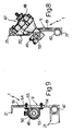
- the steering device generally indicated 47 ( Figures 2 and 4) is also fixed to the plate 9, which steering device comprises a steering box 48 and a casing 49 of elongate form in which a rack 40 ( Figures 8 and 3) is axially movable under the control of the device itself.
- the fixing of this device to the plate 9 is achieved by a pair of bolts 51 ( Figures 2 and 10) which traverse holes formed in suitable tongues 52 of the casing 49 and by means of a bracket 53 ( Figure 9) fixed, by means of screws 54, to the wall 19 and which passes around a suitably shaped part 55 of the casing 49.
- the front frame which has been described has very high rigidity and mechanical strength which are required to support the stresses transmitted by the motor vehicle wheels during driving of this, and simultaneously have a very reduced weight and dimension; this allows a simple and safe connection both of the suspensions to the frame and of this to the central frame of the support structure.
Applications Claiming Priority (2)
| Application Number | Priority Date | Filing Date | Title |
|---|---|---|---|
| IT6751087 | 1987-06-16 | ||
| IT8767510A IT1210804B (it) | 1987-06-16 | 1987-06-16 | Telaio anteriore facente parte di una struttura portante di una autovettura |
Publications (2)
| Publication Number | Publication Date |
|---|---|
| EP0301219A2 true EP0301219A2 (fr) | 1989-02-01 |
| EP0301219A3 EP0301219A3 (fr) | 1990-06-13 |
Family
ID=11303020
Family Applications (1)
| Application Number | Title | Priority Date | Filing Date |
|---|---|---|---|
| EP88109569A Withdrawn EP0301219A3 (fr) | 1987-06-16 | 1988-06-15 | Structure avant formant partie de la structure portante d'un véhicule automobile |
Country Status (3)
| Country | Link |
|---|---|
| US (1) | US4811970A (fr) |
| EP (1) | EP0301219A3 (fr) |
| IT (1) | IT1210804B (fr) |
Cited By (7)
| Publication number | Priority date | Publication date | Assignee | Title |
|---|---|---|---|---|
| DE4127037A1 (de) * | 1991-08-16 | 1993-02-18 | Porsche Ag | Hilfsrahmen fuer eine radaufhaengung eines kraftfahrzeugs |
| DE4408573A1 (de) * | 1993-03-26 | 1994-09-29 | Honda Motor Co Ltd | Hilfsrahmen und Hilfsrahmenkonstruktion |
| FR2710583A1 (fr) * | 1993-09-29 | 1995-04-07 | Peugeot | Train avant pour véhicule automobile. |
| US5560651A (en) * | 1993-03-26 | 1996-10-01 | Honda Giken Kogyo Kabushiki Kaisha | Subframe and subframe assembly |
| US6866295B2 (en) * | 2000-12-28 | 2005-03-15 | Dana Corporation | Modular cast independent front suspension subframe |
| WO2007029413A1 (fr) * | 2005-09-09 | 2007-03-15 | Toyota Jidosha Kabushiki Kaisha | Stabilisateur |
| FR2922160A1 (fr) * | 2007-10-15 | 2009-04-17 | Peugeot Citroen Automobiles Sa | Fixation de barre anti-devers sur un train avant de vehicule automobile |
Families Citing this family (14)
| Publication number | Priority date | Publication date | Assignee | Title |
|---|---|---|---|---|
| EP0873249B1 (fr) * | 1996-01-12 | 2004-04-21 | Mattel, Inc. | Systeme reglable de montage d'essieu destine a des vehicules pour enfants |
| US5718454A (en) * | 1996-01-12 | 1998-02-17 | Mattel, Inc. | Roll bar coupler for child's ride-on vehicle |
| US6470991B1 (en) * | 2000-09-14 | 2002-10-29 | Deere & Company | Tractor with front suspension |
| JP4202791B2 (ja) * | 2003-03-12 | 2008-12-24 | 本田技研工業株式会社 | 不整地走行車の車体フレーム構造 |
| US7854357B2 (en) * | 2005-07-01 | 2010-12-21 | Oms Investments, Inc. | Dispensing apparatus with locking cap |
| DE102006009300A1 (de) * | 2006-03-01 | 2007-09-06 | Daimlerchrysler Ag | Einzelradaufhängung für eine Hochlenkerachse |
| US8827028B2 (en) * | 2006-07-28 | 2014-09-09 | Polaris Industries Inc. | Side-by-side ATV |
| US7819220B2 (en) * | 2006-07-28 | 2010-10-26 | Polaris Industries Inc. | Side-by-side ATV |
| US7862085B2 (en) * | 2006-11-28 | 2011-01-04 | Gm Global Technologies Operations, Inc. | Three-dimensional vehicle frame |
| US7744104B2 (en) * | 2007-01-26 | 2010-06-29 | Honda Motor Co., Ltd. | Suspension arm and cushion arm structure for vehicle |
| US9676415B2 (en) * | 2015-03-13 | 2017-06-13 | GM Global Technology Operations LLC | Rear drive module assembly and system for mounting to a vehicle |
| DE102016214532A1 (de) | 2015-08-20 | 2017-02-23 | Ford Global Technologies, Llc | Hilfsrahmen für ein Kraftfahrzeug |
| JP6274187B2 (ja) * | 2015-11-11 | 2018-02-07 | マツダ株式会社 | リヤサブフレーム構造 |
| EP3480036A1 (fr) * | 2017-11-07 | 2019-05-08 | Volvo Car Corporation | Système de suspension de roues d'un véhicule |
Citations (3)
| Publication number | Priority date | Publication date | Assignee | Title |
|---|---|---|---|---|
| GB763794A (en) * | 1954-01-21 | 1956-12-19 | Daimler Benz Ag | Improvements relating to a combined body and frame for motor vehicles |
| DE966500C (de) * | 1939-04-20 | 1957-08-14 | Daimler Benz Ag | Elastische Verbindung eines Achsaggregattraegers von Fahrzeugen mit dem Rahmen oder Wagenkasten |
| DE1278855B (de) * | 1964-04-06 | 1968-09-26 | Sachsenring Automobilwerke | Hilfsrahmen fuer die Vorderradaufhaengung frontgetriebener Personenkraftwagen mit selbsttragender Karosserie |
Family Cites Families (6)
| Publication number | Priority date | Publication date | Assignee | Title |
|---|---|---|---|---|
| US2817557A (en) * | 1950-01-25 | 1957-12-24 | Chrysler Corp | Unitary body and frame structure for automobiles |
| DE2421207A1 (de) * | 1974-05-02 | 1975-11-20 | Daimler Benz Ag | Personenkraftwagen |
| US4240517A (en) * | 1979-04-13 | 1980-12-23 | General Motors Corporation | Powertrain and independent suspension mounting arrangement for front-wheel-drive vehicle |
| EP0087270B1 (fr) * | 1982-02-22 | 1988-08-03 | Robert Joseph Knight | Modifications au montage des ensembles de l'unité motrice et des organes de suspension de véhicules à traction avant |
| DE3635612A1 (de) * | 1985-10-21 | 1987-05-21 | Toyota Motor Co Ltd | Fahrzeugaufhaengung |
| JPS62105709A (ja) * | 1985-11-05 | 1987-05-16 | Toyota Motor Corp | 車両のサスペンシヨン |
-
1987
- 1987-06-16 IT IT8767510A patent/IT1210804B/it active
-
1988
- 1988-06-15 EP EP88109569A patent/EP0301219A3/fr not_active Withdrawn
- 1988-06-16 US US07/207,643 patent/US4811970A/en not_active Expired - Fee Related
Patent Citations (3)
| Publication number | Priority date | Publication date | Assignee | Title |
|---|---|---|---|---|
| DE966500C (de) * | 1939-04-20 | 1957-08-14 | Daimler Benz Ag | Elastische Verbindung eines Achsaggregattraegers von Fahrzeugen mit dem Rahmen oder Wagenkasten |
| GB763794A (en) * | 1954-01-21 | 1956-12-19 | Daimler Benz Ag | Improvements relating to a combined body and frame for motor vehicles |
| DE1278855B (de) * | 1964-04-06 | 1968-09-26 | Sachsenring Automobilwerke | Hilfsrahmen fuer die Vorderradaufhaengung frontgetriebener Personenkraftwagen mit selbsttragender Karosserie |
Non-Patent Citations (1)
| Title |
|---|
| AUTOMOTIVE ENGINEERING. vol. 85, no. 6, June 1977, WARRENDALE US pages 18 - 19; "Porsche 928" * |
Cited By (13)
| Publication number | Priority date | Publication date | Assignee | Title |
|---|---|---|---|---|
| DE4127037A1 (de) * | 1991-08-16 | 1993-02-18 | Porsche Ag | Hilfsrahmen fuer eine radaufhaengung eines kraftfahrzeugs |
| US5240279A (en) * | 1991-08-16 | 1993-08-31 | Dr. Ing. H.C.F. Porsche Ag | Auxiliary frame for a wheel suspension system of a motor vehicle |
| DE4408573A1 (de) * | 1993-03-26 | 1994-09-29 | Honda Motor Co Ltd | Hilfsrahmen und Hilfsrahmenkonstruktion |
| US5560651A (en) * | 1993-03-26 | 1996-10-01 | Honda Giken Kogyo Kabushiki Kaisha | Subframe and subframe assembly |
| DE4408573C2 (de) * | 1993-03-26 | 2000-11-23 | Honda Motor Co Ltd | Hilfsrahmenanordnung und Hilfsrahmen |
| FR2710583A1 (fr) * | 1993-09-29 | 1995-04-07 | Peugeot | Train avant pour véhicule automobile. |
| US6866295B2 (en) * | 2000-12-28 | 2005-03-15 | Dana Corporation | Modular cast independent front suspension subframe |
| US7380831B2 (en) | 2000-12-28 | 2008-06-03 | Dana Heavy Vehicle Systems Group, Llc | Modular cast independent front suspension subframe |
| WO2007029413A1 (fr) * | 2005-09-09 | 2007-03-15 | Toyota Jidosha Kabushiki Kaisha | Stabilisateur |
| US7946602B2 (en) | 2005-09-09 | 2011-05-24 | Toyota Jidosha Kabushiki Kaisha | Stabilizer |
| CN101263019B (zh) * | 2005-09-09 | 2011-12-14 | 丰田自动车株式会社 | 包括稳定器的悬架装置 |
| FR2922160A1 (fr) * | 2007-10-15 | 2009-04-17 | Peugeot Citroen Automobiles Sa | Fixation de barre anti-devers sur un train avant de vehicule automobile |
| EP2050597A1 (fr) * | 2007-10-15 | 2009-04-22 | Peugeot Citroën Automobiles S.A. | Fixation de barre anti-devers sur un train de véhicule automobile |
Also Published As
| Publication number | Publication date |
|---|---|
| IT8767510A0 (it) | 1987-06-16 |
| IT1210804B (it) | 1989-09-29 |
| US4811970A (en) | 1989-03-14 |
| EP0301219A3 (fr) | 1990-06-13 |
Similar Documents
| Publication | Publication Date | Title |
|---|---|---|
| EP0301219A2 (fr) | Structure avant formant partie de la structure portante d'un véhicule automobile | |
| US4811812A (en) | Rear frame forming part of a supporting structure of a motor vehicle | |
| US5368118A (en) | Torsion bar suspension for operator's platform | |
| EP1042133B1 (fr) | Bras de suspension en v destine a des vehicules | |
| GB2154966A (en) | Suspension arrangement for driven wheels | |
| US6499754B1 (en) | Vehicle suspension system | |
| CA1057780A (fr) | Systeme de suspension avant independante pour vehicule automobile | |
| EP3698998B1 (fr) | Unité de suspension arrière pour un véhicule doté d'un essieu rigide et unité de moteur électrique montée sur l'essieu | |
| US3210092A (en) | Pivotal wheel suspension for motor vehicles | |
| US2730375A (en) | Independent wheel suspensions for the steerable wheels of motor vehicles | |
| US6102416A (en) | Mount for rack and pinion steering gear | |
| US4758019A (en) | Vehicle suspension | |
| EP0301782B1 (fr) | Unité de suspension pour roue de véhicule | |
| US6322090B1 (en) | Suspension system with an oscillating, rigid axle, particularly for tractors | |
| US4087115A (en) | Motor vehicle rear wheel suspension | |
| US4982978A (en) | Rear suspension system | |
| US2856201A (en) | Independent wheel suspension for motor vehicles | |
| US4072322A (en) | Axle suspension systems for a vehicle | |
| EP0318438A1 (fr) | Dispositif de suspension pour cabines basculantes de camions commerciaux | |
| US3869015A (en) | Motor vehicle suspension | |
| JPS58112814A (ja) | 車輌サスペンシヨン・システム | |
| US3625300A (en) | Suspension of an axle unit in motor vehicles by means of a support member | |
| HU212319B (en) | Axle with longitudinal arms for motor vehicles and trailers | |
| EP0045411A2 (fr) | Suspension équilibrée à quatre ressorts pour essieux en tandem | |
| EP0217261B1 (fr) | Sous-ensemble pour suspendre élastiquement les roues d'un véhicule automobile par rapport à la caisse de ce véhicule |
Legal Events
| Date | Code | Title | Description |
|---|---|---|---|
| PUAI | Public reference made under article 153(3) epc to a published international application that has entered the european phase |
Free format text: ORIGINAL CODE: 0009012 |
|
| AK | Designated contracting states |
Kind code of ref document: A2 Designated state(s): DE ES FR GB SE |
|
| PUAL | Search report despatched |
Free format text: ORIGINAL CODE: 0009013 |
|
| AK | Designated contracting states |
Kind code of ref document: A3 Designated state(s): DE ES FR GB SE |
|
| 17P | Request for examination filed |
Effective date: 19901203 |
|
| STAA | Information on the status of an ep patent application or granted ep patent |
Free format text: STATUS: THE APPLICATION IS DEEMED TO BE WITHDRAWN |
|
| 18D | Application deemed to be withdrawn |
Effective date: 19920102 |