EP0300577A1 - Steam bath with steam generator system located in a dome applied above the cabinet - Google Patents
Steam bath with steam generator system located in a dome applied above the cabinet Download PDFInfo
- Publication number
- EP0300577A1 EP0300577A1 EP88201528A EP88201528A EP0300577A1 EP 0300577 A1 EP0300577 A1 EP 0300577A1 EP 88201528 A EP88201528 A EP 88201528A EP 88201528 A EP88201528 A EP 88201528A EP 0300577 A1 EP0300577 A1 EP 0300577A1
- Authority
- EP
- European Patent Office
- Prior art keywords
- steam
- cabinet
- generating device
- water
- boiler
- Prior art date
- Legal status (The legal status is an assumption and is not a legal conclusion. Google has not performed a legal analysis and makes no representation as to the accuracy of the status listed.)
- Granted
Links
- 238000009434 installation Methods 0.000 claims abstract description 18
- 238000010438 heat treatment Methods 0.000 claims abstract description 6
- XLYOFNOQVPJJNP-UHFFFAOYSA-N water Substances O XLYOFNOQVPJJNP-UHFFFAOYSA-N 0.000 claims description 31
- 239000011347 resin Substances 0.000 claims description 3
- 229920005989 resin Polymers 0.000 claims description 3
- 239000012528 membrane Substances 0.000 claims description 2
- 230000000382 dechlorinating effect Effects 0.000 claims 1
- 230000000694 effects Effects 0.000 claims 1
- 230000006870 function Effects 0.000 description 9
- 150000003839 salts Chemical class 0.000 description 5
- 230000008901 benefit Effects 0.000 description 4
- OKTJSMMVPCPJKN-UHFFFAOYSA-N Carbon Chemical compound [C] OKTJSMMVPCPJKN-UHFFFAOYSA-N 0.000 description 2
- 238000005452 bending Methods 0.000 description 2
- 230000000994 depressogenic effect Effects 0.000 description 2
- 238000010348 incorporation Methods 0.000 description 2
- 239000000203 mixture Substances 0.000 description 2
- 230000037452 priming Effects 0.000 description 2
- 238000004326 stimulated echo acquisition mode for imaging Methods 0.000 description 2
- NWUYHJFMYQTDRP-UHFFFAOYSA-N 1,2-bis(ethenyl)benzene;1-ethenyl-2-ethylbenzene;styrene Chemical compound C=CC1=CC=CC=C1.CCC1=CC=CC=C1C=C.C=CC1=CC=CC=C1C=C NWUYHJFMYQTDRP-UHFFFAOYSA-N 0.000 description 1
- NIXOWILDQLNWCW-UHFFFAOYSA-N acrylic acid group Chemical group C(C=C)(=O)O NIXOWILDQLNWCW-UHFFFAOYSA-N 0.000 description 1
- 230000004913 activation Effects 0.000 description 1
- 238000001816 cooling Methods 0.000 description 1
- 230000009849 deactivation Effects 0.000 description 1
- 238000006298 dechlorination reaction Methods 0.000 description 1
- 238000009792 diffusion process Methods 0.000 description 1
- 239000006185 dispersion Substances 0.000 description 1
- 239000011796 hollow space material Substances 0.000 description 1
- 238000005342 ion exchange Methods 0.000 description 1
- 239000003456 ion exchange resin Substances 0.000 description 1
- 229920003303 ion-exchange polymer Polymers 0.000 description 1
- 239000004973 liquid crystal related substance Substances 0.000 description 1
- 238000012423 maintenance Methods 0.000 description 1
- 230000007257 malfunction Effects 0.000 description 1
- 238000004519 manufacturing process Methods 0.000 description 1
- 239000000463 material Substances 0.000 description 1
- 238000000034 method Methods 0.000 description 1
- 238000000746 purification Methods 0.000 description 1
- 230000003134 recirculating effect Effects 0.000 description 1
- 230000001172 regenerating effect Effects 0.000 description 1
- 230000008439 repair process Effects 0.000 description 1
- 238000004092 self-diagnosis Methods 0.000 description 1
- 230000000153 supplemental effect Effects 0.000 description 1
Images


Classifications
-
- A—HUMAN NECESSITIES
- A61—MEDICAL OR VETERINARY SCIENCE; HYGIENE
- A61H—PHYSICAL THERAPY APPARATUS, e.g. DEVICES FOR LOCATING OR STIMULATING REFLEX POINTS IN THE BODY; ARTIFICIAL RESPIRATION; MASSAGE; BATHING DEVICES FOR SPECIAL THERAPEUTIC OR HYGIENIC PURPOSES OR SPECIFIC PARTS OF THE BODY
- A61H33/00—Bathing devices for special therapeutic or hygienic purposes
- A61H33/06—Artificial hot-air or cold-air baths; Steam or gas baths or douches, e.g. sauna or Finnish baths
-
- A—HUMAN NECESSITIES
- A61—MEDICAL OR VETERINARY SCIENCE; HYGIENE
- A61H—PHYSICAL THERAPY APPARATUS, e.g. DEVICES FOR LOCATING OR STIMULATING REFLEX POINTS IN THE BODY; ARTIFICIAL RESPIRATION; MASSAGE; BATHING DEVICES FOR SPECIAL THERAPEUTIC OR HYGIENIC PURPOSES OR SPECIFIC PARTS OF THE BODY
- A61H33/00—Bathing devices for special therapeutic or hygienic purposes
- A61H33/06—Artificial hot-air or cold-air baths; Steam or gas baths or douches, e.g. sauna or Finnish baths
- A61H33/063—Heaters specifically designed therefor
-
- A—HUMAN NECESSITIES
- A61—MEDICAL OR VETERINARY SCIENCE; HYGIENE
- A61H—PHYSICAL THERAPY APPARATUS, e.g. DEVICES FOR LOCATING OR STIMULATING REFLEX POINTS IN THE BODY; ARTIFICIAL RESPIRATION; MASSAGE; BATHING DEVICES FOR SPECIAL THERAPEUTIC OR HYGIENIC PURPOSES OR SPECIFIC PARTS OF THE BODY
- A61H33/00—Bathing devices for special therapeutic or hygienic purposes
- A61H33/06—Artificial hot-air or cold-air baths; Steam or gas baths or douches, e.g. sauna or Finnish baths
- A61H33/10—Devices on tubs for steam baths
Definitions
- the location of the steam generator separate and, frequently, a considerable distance from the cabinet means that the lines conveying the steam to the cabinet run a course that facilitates heat dispersion and thus jeopardizes the performance of the sauna as a whole.
- the overall object of the present invention is to obviate the above-mentioned difficulties by embodying a steam generator which, complete with its control devices, can be installed directly above a steam bath cabinet, thus minimizing the number of electrical and hydraulic linkages external to the whole and necessary for its functioning, and also minimizing the lenght run by the electrical and hydraulic linkages between steam generator and cabinet, in this way embodying a steam bath cabinet installation which is both compact and without other visible elements.
- the present invention embodies a steam generator of the type comprising an electric steam boiler for steam generation and a pipe connecting the said boiler to steam inlet ports within a steam bath cabinet, wherein the whole is completely contained in a generally box-shaped container the dimensions of the base of which are the same as those of the upper portion of the said cabinet onto the top of which the said container is applied, forming with it a single whole.
- a sauna or steam bath cabinet installation embodied in accordance with the innovative principles of the invetion, comprises a generally box-like container 10 which holds all the control and steam generation devices and which is realized, for example, with fibreglass-reinforced acrylic material and is disposed on the top of a cabinet (shower cubicle) into which the steam produced by the said generating devices is conveyed.
- the generally box-like container 10 has base dimensions that cover, with a perfect closure, the upper part of the cabinet.
- the said system consists of an electric steam boiler 12 featuring armoured electrical resistances 13 and connected by means of a pipe 14 to water-purification cartridges 15 which are connected in series (e.g. three in number: two being ion-exchange resin cartridges for water decalcification and the third containing activated charcoal for water dechlorination).
- a pipe 16 leads to a container 17 for salt (for regenerating the resins in the ion-exchange cartridges) and from this to a supply solenoid 18 which by means of a pipe 19 supplies the above-described system with cold water from the mains.
- a pipe 20 from the boiler 12 connects the boiler to a drain-trap 21 which is in turn connected by a pipe 22 to a drain 23 and, by a pipe 24, to a second discharge or drain solenoid 25, also connected to the pipe 19.
- An air intake 26 is located intermediately between the drain-trap 21 and the drain 23.
- cartridges 15 and the drain-trap 21 are supplemental components of the steam generation and control system proper, they are not incorporated in the container 10; given their small bulk, they can readily be hidden from view by replacing them for example in a hollow space between the back wall of the steam bath cabinet and the wall abutting this; such components are in any case the only ones external to the container 10 and, moreover, in any embodiment different from that here given as an exemplification of application of the innovative principles of the invention, they can either not feature at all or else be replaced by functionally equivalent devices placed within the container 10.
- a tube 27 conveys the steam generated in the boiler 12 to a delivery port 28 communicating with the interior of the cabinet 11.
- a system for recirculating the atmosphere in the cabinet 11 consisting of a duct 29 containing a fan 30 and series-connected electrical resistances 31.
- the duct 29 communicates with the interior of the cabinet 11: the first end (closest to the fan) communicates directly therewith and the second end communicates with the interior of the cabinet proximally to the steam delivery port 28.
- the manner of operating of the entire installation in question is controlled by an electronic control unit 32 operated by a device 33 inside the cabinet 11.
- the unit 32 and the operating device 33 are fed, through an electric switch 34 controlled by a mechanical pushbutton 35 located on the ceiling of the steam bath cabinet, through the intermediary of an electrical connection 36 to an external electric line.
- the unit 32 and the corresponding operating device 33 can be realized in any manner and can operate with any desired cycle, compatibly with the operational requirements of the steam generator system.
- the manner of operating of the steam bath cabinet installation will for the sake of convenience be referred to a specific embodiment on an electronic control unit and of a corresponding operating device embodied incorporating a microprocessor system to the programmed special functions of which reference will be made, though this is not limiting as regards the invention overall or as regards the scope of its claims and should be understood as exemplifying a possible practical embodiment.
- the armoured electrical resistances 13 are activated by the electronic control unit 32.
- the electronic control unit 32 de-energizes the supply solenoid 18, so interrupting the mains water supply to the boiler.
- the water thus present in the boiler is heated by the armoured resistances 13 and, after a certain time (approximately 6 to 7 minutes), steam begins to form in the boiler 12. This steam, flowing through the pipe 27, is introduced through the delivery port 28 into the cabinet 11.
- the fan 30, activated by the electronic control unit 42 aspirates the mixture of steam and air in the cabinet and conveys it to the inside of the duct 29 where it is heated on coming into contact with the electrical resistances 31 and is then delivered once again to the interior of the steam bath cabinet from the other end of the duct proximal to the delivery port 28 and thus mixes with the steam coming from the boiler 12.
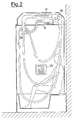
- air/steam mixture similar to that diagrammatically illustrated in Figure 2, which shows how the said forced-circulation system enables the steam to pervade the entire interior of the cabinet in an evenly distributed manner.
- a sauna cycle with steam generation terminates either when the water in the boiler reaches the minimum level (detected by the first sensor of suitable type) or when the electronic control unit 32 is informed of the depression of a key marked STOP on the keyboard of the operating device 33.
- the electronic control unit 32 then deactivates all the heating resistances in the system and starts-up a system rinsing cycle.
- This cycle consists of activation of the drain solenoid 25 which permits the mains water from the pipe 19 to reach the drain-trap 21 through the pipe 24.
- the drain-trap 21 is composed (as is shown in Figure 1 and, more clarly, in Figure 3, 4 and 5) of three pipes 20, 22, 24 interconnected by a T-joint and bent upwards so as to be parallel and vertical for a certain section before again bending so as to reach, as already stated, the following: the pipe 20 reaches the boiler 12; the pipe 24 the discharge or drain solenoid 25; the pipe 22, by its downward bend, the drain 23.
- Figure 3 which illustrates the drain-trap in the unprimed condition when the sauna or steam bath cabinet installation is inoperative (switched off), a condition of equilibrium is obtained in the three pipes forming the drain-trap, which remain filled with water up to the level indicated by A-A.
- Figure 3 also illustrates the condition existing when the steam bath cabinet installation is in operation, when the pressure set-up by the steam in the boiler is transmitted through the pipe 20 to the drain-trap and the water-levels in the drain-trap are modified, reaching the levels indicated by B-B.
- the condition illustrated in Figure 4 subsists: flowing through the pipe 24, the water reaches the drain-trap 21 and branches off into the pipes 20 and 22, in this way reaching, through the pipe 20, the boiler 12 which it rinses; then, through the pipe 22, it reaches the discharge system at 25, priming the drain-trap 21.
- the discharge or drain solenoid 25 remains activated for sufficiently long to ensure that the priming takes place (for example 10 seconds) and then the electronic control unit 32 deactivates it. When this occurs the drain-trap system 25 enters the water discharge phase as illustrated in Figure 5.
- the pipe 24 is closed at its upper end by the solenoid 25 and is therefore extraneous to the functioning of the drain trap while the water in the pipes 20 and 22 flows (as a result also of the air intake 26 in the descending section of the pipe 22) to the drain 23, at the same time drawing off the water present in the boiler 12 and so emptying it.
- the system is in this way rinsed out and emptied of all residual water in an effective and completely automatic manner.
- the system is therefore at once ready for providing another steam bath cycle or else for total deactivation, i.e. by depression of the pushbutton 35 on the ceiling of the cabinet so as completely to cut-out the power feed to the steam bath electrical system. This is done through the agency of the switch 34.
- the duct 29 containing the fan 30 and the electrical resistances provides other useful and convenient possibilities: it is for example thereby possible to activate the fan and the resistances separately from the steam generation system and so cause warm air to circulate in the cabinet, which is useful for pre-heating the cabinet pending the start of steam generation (i.e. while the water in the boiler 12 is being heated), or, on completion of the steam bath cycle, to dry the bather and/or the interior of the cabinet.
- the microprocessor operated electronic control system makes readily available an entire series of functions additional to the basic functions for steam bath operation simply by storing in the memory of the system, during manufacture, the appropriate programme. Such additional functions augment practicality and facility of use.
- the type of climate selected and the instantaneous temperature inside the steam bath cabinet (measured by a suitable sensor located in the cabinet and connected to the electronic control unit 32).
- the container 17 requires to be periodically topped up with salt to regenerate the resins in the cartridges 15.
- a low salt level in the container 17 can be automatically indicated on the alphanumeric display by means of a suitable phrase that appears after a certain number of steam bath cycles. This prevents personnel oversights and ensures timely salt refurnishment.
- control unit employing a microprocessor permits, at low cost, a wide range of additional functions which the bather can make use of without difficulty.
- additional functions previously described, is the reading of the internal temperature of the steam bath cabinet.
- a container is available immediately above the cabinet makes it possible to add, readily and with a minimum of connections, various other devices that can be disposed in the space within the said container that is not occupied by the steam generation system and its control devices.
- a radio receiver system controllable by the microprocessor system capable, for instance, of memorizing a certain number of radio channels through the agency of the previously mentioned operating device 33 with keyboard; the sound diffusion can be readily disposed in the ceiling of the steam bath cabinet.
- Another possible device is a lamp 37 for lighting the interior of the steam bath cabinet that can for instance be fed through the intermediary of the switch 34 and will also seve as a clearly visible indication that the steam bath cabinet installation electrical system is on.
Landscapes
- Health & Medical Sciences (AREA)
- Public Health (AREA)
- Epidemiology (AREA)
- Pain & Pain Management (AREA)
- Physical Education & Sports Medicine (AREA)
- Rehabilitation Therapy (AREA)
- Life Sciences & Earth Sciences (AREA)
- Animal Behavior & Ethology (AREA)
- General Health & Medical Sciences (AREA)
- Veterinary Medicine (AREA)
- Devices For Medical Bathing And Washing (AREA)
Abstract
Description
- When installating cabinets equipped for use as saunas, or steam baths, one of the chief problems is how best to lay out the ensemble represented by the steam generator and its various control devices. The said ensemble is generally separate from the structure of the cabinet and, for its installation and connection to the cabinet, a considerable amount of building work is often necessary in order to dispose the different lines conveying the steam from the steam generator to the cabinet and also the electric wiring permitting control and regulation of the steam generator. So as not to have to perform such building work, the lines and wiring are, alternatively, disposed externally and thus, remaining in view, give a very unsatisfactory result in point of general appearance.
- In addition, the location of the steam generator separate and, frequently, a considerable distance from the cabinet means that the lines conveying the steam to the cabinet run a course that facilitates heat dispersion and thus jeopardizes the performance of the sauna as a whole.
- The overall object of the present invention is to obviate the above-mentioned difficulties by embodying a steam generator which, complete with its control devices, can be installed directly above a steam bath cabinet, thus minimizing the number of electrical and hydraulic linkages external to the whole and necessary for its functioning, and also minimizing the lenght run by the electrical and hydraulic linkages between steam generator and cabinet, in this way embodying a steam bath cabinet installation which is both compact and without other visible elements.
- To attain the said object, the present invention embodies a steam generator of the type comprising an electric steam boiler for steam generation and a pipe connecting the said boiler to steam inlet ports within a steam bath cabinet, wherein the whole is completely contained in a generally box-shaped container the dimensions of the base of which are the same as those of the upper portion of the said cabinet onto the top of which the said container is applied, forming with it a single whole.
- The object of the invention, and its advantages over the known art, will become more apparent from an examination of the following description thereof, with reference to the appended drawings, in which:
- - Figure 1 is a vertically sectioned diagrammatic view of a steam bath cabinet embodied according to the innovative principles of the invention;
- - Figure 2 is a vertically sectioned diagrammatic view of a steam bath cabinet embodied according to the invention, showing the circulation of a steam within it;
- - Figure 3 is a diagrammatic illustration of an automatic drain-trap type water discharde device in the unprimed condition;
- - Figure 4 is a diagrammatic illustration of the water discharge device of Figure 3 with the drain-trap in the primed condition;
- - Figure 5 is a diagrammatic illustration of the water discharge device of Figure 3 in the discharge condition.
- With reference to the Figures, a sauna or steam bath cabinet installation, embodied in accordance with the innovative principles of the invetion, comprises a generally box-
like container 10 which holds all the control and steam generation devices and which is realized, for example, with fibreglass-reinforced acrylic material and is disposed on the top of a cabinet (shower cubicle) into which the steam produced by the said generating devices is conveyed. - The generally box-
like container 10 has base dimensions that cover, with a perfect closure, the upper part of the cabinet. - For the sake convenience, reference will hereinafter be made to a particular system for generating and controlling steam, such system being contained in the
container 10, without thereby in any way limiting the scope of the invention. - As Figure 1 shows, the said system consists of an
electric steam boiler 12 featuring armouredelectrical resistances 13 and connected by means of apipe 14 to water-purification cartridges 15 which are connected in series (e.g. three in number: two being ion-exchange resin cartridges for water decalcification and the third containing activated charcoal for water dechlorination). From the cartridges 15 apipe 16 leads to acontainer 17 for salt (for regenerating the resins in the ion-exchange cartridges) and from this to asupply solenoid 18 which by means of apipe 19 supplies the above-described system with cold water from the mains. Apipe 20 from theboiler 12 connects the boiler to a drain-trap 21 which is in turn connected by apipe 22 to adrain 23 and, by apipe 24, to a second discharge ordrain solenoid 25, also connected to thepipe 19. Anair intake 26 is located intermediately between the drain-trap 21 and thedrain 23. As thecartridges 15 and the drain-trap 21 are supplemental components of the steam generation and control system proper, they are not incorporated in thecontainer 10; given their small bulk, they can readily be hidden from view by replacing them for example in a hollow space between the back wall of the steam bath cabinet and the wall abutting this; such components are in any case the only ones external to thecontainer 10 and, moreover, in any embodiment different from that here given as an exemplification of application of the innovative principles of the invention, they can either not feature at all or else be replaced by functionally equivalent devices placed within thecontainer 10. - In the exemplifying embodiment here described, a
tube 27 conveys the steam generated in theboiler 12 to adelivery port 28 communicating with the interior of thecabinet 11. Within thecontainer 10 there is also a system for recirculating the atmosphere in thecabinet 11, consisting of a duct 29 containing afan 30 and series-connectedelectrical resistances 31. At its ends, the duct 29 communicates with the interior of the cabinet 11: the first end (closest to the fan) communicates directly therewith and the second end communicates with the interior of the cabinet proximally to thesteam delivery port 28. - The manner of operating of the entire installation in question is controlled by an
electronic control unit 32 operated by adevice 33 inside thecabinet 11. Theunit 32 and theoperating device 33 are fed, through anelectric switch 34 controlled by amechanical pushbutton 35 located on the ceiling of the steam bath cabinet, through the intermediary of anelectrical connection 36 to an external electric line. - The
unit 32 and thecorresponding operating device 33 can be realized in any manner and can operate with any desired cycle, compatibly with the operational requirements of the steam generator system. Hereinafter the manner of operating of the steam bath cabinet installation will for the sake of convenience be referred to a specific embodiment on an electronic control unit and of a corresponding operating device embodied incorporating a microprocessor system to the programmed special functions of which reference will be made, though this is not limiting as regards the invention overall or as regards the scope of its claims and should be understood as exemplifying a possible practical embodiment. - The manner of operating of the steam bath cabinet installation in question, employing the said microprocessor system, is as follows.
- When the mechanically operated
pushbutton 35 is depressed, voltage is supplied to theelctronic control unit 32 and to thecorresponding operating device 33 which, for example, consists of a membrane keyboard (which is thus impermeable as required) and an alphanumeric display, for example employing liquid crystals. When thepushbutton 35 has been depressed so as to supply the system with voltage, depression of a pushbutton marked SAUNA on the keyboard of theelectronic control unit 32 activates thesupply solenoid 18 and thus flowing through thepipe 16 the mains water reaches, through thepipe 19, thesalt container 17, passes through this and through thecartridges 15 where it is dechlorinated and decalcified and, lastly, reaches theboiler 12. When a minimum water level has been attained in theboiler 12, so that the armouredelectrical resistances 13 are covered (which level is detected by an appropriate first sensor, not shown, inside the boiler, which sends the information to the electronic control unit 42), the armouredelectrical resistances 13 are activated by theelectronic control unit 32. When a maximum water level is reached (this also being detected by a suitable sensor, not shown), theelectronic control unit 32 de-energizes thesupply solenoid 18, so interrupting the mains water supply to the boiler. The water thus present in the boiler is heated by thearmoured resistances 13 and, after a certain time (approximately 6 to 7 minutes), steam begins to form in theboiler 12. This steam, flowing through thepipe 27, is introduced through thedelivery port 28 into thecabinet 11. Once the steam has been delivered into the cabinet, to prevent it from cooling and condensing, thefan 30, activated by the electronic control unit 42, aspirates the mixture of steam and air in the cabinet and conveys it to the inside of the duct 29 where it is heated on coming into contact with theelectrical resistances 31 and is then delivered once again to the interior of the steam bath cabinet from the other end of the duct proximal to thedelivery port 28 and thus mixes with the steam coming from theboiler 12. There is in this way obtained and air/steam mixture similar to that diagrammatically illustrated in Figure 2, which shows how the said forced-circulation system enables the steam to pervade the entire interior of the cabinet in an evenly distributed manner. - Through the agency of the
operating device 33 it is then possible to select the desired climate inside the steam bath cabinet (for example: temperate, medium, hot, etc.); this selection is carried out by theelectronic control unit 32 which appropriately controls the different electrical resistances (13, 31) in the system so as to keep the selected climate constant inside the steam bath cabinet. A sauna cycle with steam generation terminates either when the water in the boiler reaches the minimum level (detected by the first sensor of suitable type) or when theelectronic control unit 32 is informed of the depression of a key marked STOP on the keyboard of theoperating device 33. Alternatively, provision can be made for a timer in theelectronic control unit 32, which timer is programmable through the agency of theoperating device 33 for a desired operating period. On expiry of the pre-set time, the said timer starts-up the same procedure obtained by the depression of the STOP key. - In whatever manner the end of the said sauna cycle is brought about (minimum water level in the boiler, depression of the STOP key, expiry of the pre-set timer time), the
electronic control unit 32 then deactivates all the heating resistances in the system and starts-up a system rinsing cycle. This cycle consists of activation of thedrain solenoid 25 which permits the mains water from thepipe 19 to reach the drain-trap 21 through thepipe 24. The drain-trap 21 is composed (as is shown in Figure 1 and, more clarly, in Figure 3, 4 and 5) of threepipes pipe 20 reaches theboiler 12; thepipe 24 the discharge ordrain solenoid 25; thepipe 22, by its downward bend, thedrain 23. As can be seen from Figure 3, which illustrates the drain-trap in the unprimed condition when the sauna or steam bath cabinet installation is inoperative (switched off), a condition of equilibrium is obtained in the three pipes forming the drain-trap, which remain filled with water up to the level indicated by A-A. Figure 3 also illustrates the condition existing when the steam bath cabinet installation is in operation, when the pressure set-up by the steam in the boiler is transmitted through thepipe 20 to the drain-trap and the water-levels in the drain-trap are modified, reaching the levels indicated by B-B. The length of the sections of thepipes - When the discharge or
drain solenoid 25 is activated by theelectronic control unit 32, the condition illustrated in Figure 4 subsists: flowing through thepipe 24, the water reaches the drain-trap 21 and branches off into thepipes pipe 20, theboiler 12 which it rinses; then, through thepipe 22, it reaches the discharge system at 25, priming the drain-trap 21. The discharge ordrain solenoid 25 remains activated for sufficiently long to ensure that the priming takes place (for example 10 seconds) and then theelectronic control unit 32 deactivates it. When this occurs the drain-trap system 25 enters the water discharge phase as illustrated in Figure 5. In this phase thepipe 24 is closed at its upper end by thesolenoid 25 and is therefore extraneous to the functioning of the drain trap while the water in thepipes air intake 26 in the descending section of the pipe 22) to thedrain 23, at the same time drawing off the water present in theboiler 12 and so emptying it. The system is in this way rinsed out and emptied of all residual water in an effective and completely automatic manner. The system is therefore at once ready for providing another steam bath cycle or else for total deactivation, i.e. by depression of thepushbutton 35 on the ceiling of the cabinet so as completely to cut-out the power feed to the steam bath electrical system. This is done through the agency of theswitch 34. - In addition to improving steam circulation inside the steam bath cabinet, the duct 29 containing the
fan 30 and the electrical resistances provides other useful and convenient possibilities: it is for example thereby possible to activate the fan and the resistances separately from the steam generation system and so cause warm air to circulate in the cabinet, which is useful for pre-heating the cabinet pending the start of steam generation (i.e. while the water in theboiler 12 is being heated), or, on completion of the steam bath cycle, to dry the bather and/or the interior of the cabinet. - The microprocessor operated electronic control system makes readily available an entire series of functions additional to the basic functions for steam bath operation simply by storing in the memory of the system, during manufacture, the appropriate programme. Such additional functions augment practicality and facility of use. In the first place, provision can be made for a wide variety of messages which indicate on the alphanumeric display on the
operating device 33 the different enable functions or functions that can be enabled, for example the phase of the steam bath cycle can be indicated by phrases such as: WAIT FOR STEAM; STEAM READY; PIPE RINSING; etc. In addition, the type of climate selected and the instantaneous temperature inside the steam bath cabinet (measured by a suitable sensor located in the cabinet and connected to the electronic control unit 32). Moreover, should the installation malfunction, provision can be made for self-diagnosis messages which are of great help to technical assistance personnel for rapid identification and repair of the fault. Such messages are also advantageous for the purpose of routine maintenance. For example, thecontainer 17 requires to be periodically topped up with salt to regenerate the resins in thecartridges 15. A low salt level in thecontainer 17 can be automatically indicated on the alphanumeric display by means of a suitable phrase that appears after a certain number of steam bath cycles. This prevents personnel oversights and ensures timely salt refurnishment. - The very considerable advantages brought by the steam bath cabinet installation in accordance with the invention are thus evident.
- The incorporation of all the components forming the steam generation device and related controls in a container to be fitted above the cabinet (the dimensions of the
container 10 can of course vary in relation to the cabinet used, as is also the case with the disposition within thecontainer 10 of the different elements constituting the steam bath system) makes it possible to obtain a steam bath cabinet installation of very moderate dimensions, the necessary surface area for the installation being practically that of the base of the cabinet. The said incorporation also brings considerable aesthetic advantage in that, apart from the cabinet itself, there is no other element in view (and thus no steam pipe in view), this being achieved without the need for building works for installing pipes other than the water discharge system pipes. Installation time and costs are in consequence reduced. Other advantages are an optimal steam circulation obtained by means of the duct 29 which not only keeps the steam circulating, thus aiding even distribution within the cabinet, but also maintains it at the pre-set temperature. The duct 29 can be used, also separately from the steam bath function, to pre-heat the cabinet and to dry it. - The previously described water-discharge system employing a drain-trap means that a steam bath cabinet installation can be embodied that calls for no manual operation for filling and emptying the
boiler 12, at the same time ensuring that after use of the steam bath cabinet the steam generation system can be rinsed, all this being achieved with a very economical drain-trap device. - Lastly, the control unit employing a microprocessor permits, at low cost, a wide range of additional functions which the bather can make use of without difficulty. One of such additional functions, previously described, is the reading of the internal temperature of the steam bath cabinet.
- Further, the fact that a container is available immediately above the cabinet makes it possible to add, readily and with a minimum of connections, various other devices that can be disposed in the space within the said container that is not occupied by the steam generation system and its control devices. For example, provision can be made for a radio receiver system controllable by the microprocessor system capable, for instance, of memorizing a certain number of radio channels through the agency of the previously mentioned
operating device 33 with keyboard; the sound diffusion can be readily disposed in the ceiling of the steam bath cabinet. Another possible device is alamp 37 for lighting the interior of the steam bath cabinet that can for instance be fed through the intermediary of theswitch 34 and will also seve as a clearly visible indication that the steam bath cabinet installation electrical system is on.
Claims (13)
Applications Claiming Priority (2)
| Application Number | Priority Date | Filing Date | Title |
|---|---|---|---|
| IT2207887U | 1987-07-24 | ||
| IT2207887U IT211945Z2 (en) | 1987-07-24 | 1987-07-24 | STEAM SAUNA WITH A VAPORIZER SYSTEM PLACED IN A DOME APPLIED UPPER TO THE CAB. |
Publications (2)
| Publication Number | Publication Date |
|---|---|
| EP0300577A1 true EP0300577A1 (en) | 1989-01-25 |
| EP0300577B1 EP0300577B1 (en) | 1992-03-11 |
Family
ID=11191152
Family Applications (1)
| Application Number | Title | Priority Date | Filing Date |
|---|---|---|---|
| EP19880201528 Expired EP0300577B1 (en) | 1987-07-24 | 1988-07-15 | Steam bath with steam generator system located in a dome applied above the cabinet |
Country Status (6)
| Country | Link |
|---|---|
| EP (1) | EP0300577B1 (en) |
| JP (1) | JP2571829B2 (en) |
| AU (1) | AU610908B2 (en) |
| DE (1) | DE3869005D1 (en) |
| ES (1) | ES2030157T3 (en) |
| IT (1) | IT211945Z2 (en) |
Cited By (22)
| Publication number | Priority date | Publication date | Assignee | Title |
|---|---|---|---|---|
| US5069207A (en) * | 1990-07-23 | 1991-12-03 | Lin Shin Hsiung | Physiotherapy healthy device |
| WO1993009752A1 (en) * | 1991-11-22 | 1993-05-27 | Nordic Saunas Limited | Climate chamber |
| US5224224A (en) * | 1991-01-11 | 1993-07-06 | Kohler Co. | Foot bathing fixture |
| US5255399A (en) * | 1990-12-31 | 1993-10-26 | Park Hun C | Far infrared rays sauna bath assembly |
| US5289599A (en) * | 1991-01-11 | 1994-03-01 | Kohler Co. | Foot bathing fixture |
| EP0534918A3 (en) * | 1991-09-27 | 1994-03-30 | Filipponi A & C Sea Snc | |
| ES2083310A1 (en) * | 1991-04-29 | 1996-04-01 | Millaka S A | Improvements to steam generator apparatus for saunas |
| US5628073A (en) * | 1995-07-27 | 1997-05-13 | Watkins Manufacturing Corp. | Sauna |
| EP0747032A3 (en) * | 1995-05-11 | 1997-12-29 | Kabushiki Kaisha Keibi Seisakusho | Portable sauna |
| EP0779067A3 (en) * | 1995-12-12 | 1998-03-11 | Paul Haslauer | Hot air/steam bath cabinet |
| EP0880960A3 (en) * | 1997-05-26 | 1999-11-17 | Jacuzzi Europe Spa | Steam and hot air generating apparatus for use in shower cubicles or the like |
| US5987662A (en) * | 1997-04-02 | 1999-11-23 | Kiyokawa; Shin | Sauna device |
| WO2000044331A1 (en) * | 1999-01-28 | 2000-08-03 | Vitasalin Ag | Full body atomised bath and method for providing a full body atomised bath |
| EP1219281A1 (en) * | 2000-12-19 | 2002-07-03 | Hermann Kelmayr | Shower cubicle |
| US6681417B2 (en) * | 2002-04-04 | 2004-01-27 | Gestion Ultra International Inc. | Therapeutic shower enclosure |
| EP1484044A3 (en) * | 2003-06-05 | 2005-01-12 | Hansgrohe AG | Steam outlet device from a steam generator to the inner of a steam booth |
| EP1561447A1 (en) * | 2004-02-05 | 2005-08-10 | Hansgrohe AG | Outflow arrangement for a steam cabin |
| US6965097B2 (en) * | 2003-03-26 | 2005-11-15 | Seung Woo Lee | Control device for an infrared ray sauna facility |
| GB2413955A (en) * | 2004-05-13 | 2005-11-16 | John Mcdermott | Shower and dryer |
| CN102670394A (en) * | 2012-05-07 | 2012-09-19 | 林智勇 | Intelligent fumigation therapy instrument for arthritis |
| CN102755243A (en) * | 2012-06-27 | 2012-10-31 | 林智勇 | Intelligent arthritis fumigation cover |
| US9283143B2 (en) | 2011-12-08 | 2016-03-15 | Nikita Krasilnikov | Mobile sauna |
Families Citing this family (3)
| Publication number | Priority date | Publication date | Assignee | Title |
|---|---|---|---|---|
| JP4891489B2 (en) * | 2001-05-16 | 2012-03-07 | 株式会社ハーマン | Mist equipment |
| CN102755247B (en) * | 2012-07-06 | 2014-04-30 | 林智勇 | Temperature regulation device of intelligent fumigation cover |
| KR102360834B1 (en) * | 2015-02-02 | 2022-02-10 | 주식회사 콜러노비타 | Steam generator |
Citations (7)
| Publication number | Priority date | Publication date | Assignee | Title |
|---|---|---|---|---|
| EP0059407A1 (en) * | 1981-02-24 | 1982-09-08 | Günter Schüssler | Bubble bath with integrated compartments for water overflow and level equalization, water conditioning chambers, and automatic or forced back-washing of the filter means |
| DE3319232A1 (en) * | 1983-05-27 | 1984-11-29 | Willi 5208 Eitorf Schiefelbusch | Device for the generation of steam |
| DE3511436A1 (en) * | 1985-03-29 | 1986-10-02 | Wella Ag, 6100 Darmstadt | System for humidifying the air in a sauna |
| DE3615194A1 (en) * | 1985-05-06 | 1986-11-06 | Sven-Olof Halmstad Janson | Apparatus for steam baths |
| DE8631342U1 (en) * | 1986-11-22 | 1987-03-05 | Hoesch Metall + Kunststoffwerk GmbH & Co, 52372 Kreuzau | Remote control element for wet areas |
| WO1987003194A1 (en) * | 1985-12-02 | 1987-06-04 | Yli Kovero Risto T | A method of heating a sauna and a sauna stove |
| DE8711541U1 (en) * | 1987-08-26 | 1987-11-05 | EOS-Werke Günther GmbH, 6349 Driedorf | Sauna service and operating station |
Family Cites Families (2)
| Publication number | Priority date | Publication date | Assignee | Title |
|---|---|---|---|---|
| AU2075470A (en) * | 1970-10-06 | 1972-04-13 | Feil Julius | Improved steambath |
| EP0024714A3 (en) * | 1979-08-30 | 1981-06-03 | Portasauna Limited | Bathing device |
-
1987
- 1987-07-24 IT IT2207887U patent/IT211945Z2/en active
-
1988
- 1988-07-15 DE DE88201528T patent/DE3869005D1/en not_active Expired - Fee Related
- 1988-07-15 ES ES88201528T patent/ES2030157T3/en not_active Expired - Lifetime
- 1988-07-15 EP EP19880201528 patent/EP0300577B1/en not_active Expired
- 1988-07-21 AU AU19280/88A patent/AU610908B2/en not_active Ceased
- 1988-07-22 JP JP63181969A patent/JP2571829B2/en not_active Expired - Lifetime
Patent Citations (7)
| Publication number | Priority date | Publication date | Assignee | Title |
|---|---|---|---|---|
| EP0059407A1 (en) * | 1981-02-24 | 1982-09-08 | Günter Schüssler | Bubble bath with integrated compartments for water overflow and level equalization, water conditioning chambers, and automatic or forced back-washing of the filter means |
| DE3319232A1 (en) * | 1983-05-27 | 1984-11-29 | Willi 5208 Eitorf Schiefelbusch | Device for the generation of steam |
| DE3511436A1 (en) * | 1985-03-29 | 1986-10-02 | Wella Ag, 6100 Darmstadt | System for humidifying the air in a sauna |
| DE3615194A1 (en) * | 1985-05-06 | 1986-11-06 | Sven-Olof Halmstad Janson | Apparatus for steam baths |
| WO1987003194A1 (en) * | 1985-12-02 | 1987-06-04 | Yli Kovero Risto T | A method of heating a sauna and a sauna stove |
| DE8631342U1 (en) * | 1986-11-22 | 1987-03-05 | Hoesch Metall + Kunststoffwerk GmbH & Co, 52372 Kreuzau | Remote control element for wet areas |
| DE8711541U1 (en) * | 1987-08-26 | 1987-11-05 | EOS-Werke Günther GmbH, 6349 Driedorf | Sauna service and operating station |
Cited By (28)
| Publication number | Priority date | Publication date | Assignee | Title |
|---|---|---|---|---|
| US5069207A (en) * | 1990-07-23 | 1991-12-03 | Lin Shin Hsiung | Physiotherapy healthy device |
| US5255399A (en) * | 1990-12-31 | 1993-10-26 | Park Hun C | Far infrared rays sauna bath assembly |
| US5289599A (en) * | 1991-01-11 | 1994-03-01 | Kohler Co. | Foot bathing fixture |
| US5224224A (en) * | 1991-01-11 | 1993-07-06 | Kohler Co. | Foot bathing fixture |
| ES2083310A1 (en) * | 1991-04-29 | 1996-04-01 | Millaka S A | Improvements to steam generator apparatus for saunas |
| EP0534918A3 (en) * | 1991-09-27 | 1994-03-30 | Filipponi A & C Sea Snc | |
| WO1993009752A1 (en) * | 1991-11-22 | 1993-05-27 | Nordic Saunas Limited | Climate chamber |
| EP0747032A3 (en) * | 1995-05-11 | 1997-12-29 | Kabushiki Kaisha Keibi Seisakusho | Portable sauna |
| US5950254A (en) * | 1995-05-11 | 1999-09-14 | Kabushiki Kaisha Keibi Seisakusho | Portable sauna |
| US5628073A (en) * | 1995-07-27 | 1997-05-13 | Watkins Manufacturing Corp. | Sauna |
| EP0779067A3 (en) * | 1995-12-12 | 1998-03-11 | Paul Haslauer | Hot air/steam bath cabinet |
| US5987662A (en) * | 1997-04-02 | 1999-11-23 | Kiyokawa; Shin | Sauna device |
| EP0880960A3 (en) * | 1997-05-26 | 1999-11-17 | Jacuzzi Europe Spa | Steam and hot air generating apparatus for use in shower cubicles or the like |
| US6500197B1 (en) | 1999-01-28 | 2002-12-31 | Vitasalin Ag | Full-body atomised bath and method for providing a full body atomised bath |
| WO2000044331A1 (en) * | 1999-01-28 | 2000-08-03 | Vitasalin Ag | Full body atomised bath and method for providing a full body atomised bath |
| EP1219281A1 (en) * | 2000-12-19 | 2002-07-03 | Hermann Kelmayr | Shower cubicle |
| US6681417B2 (en) * | 2002-04-04 | 2004-01-27 | Gestion Ultra International Inc. | Therapeutic shower enclosure |
| WO2003084456A3 (en) * | 2002-04-04 | 2004-02-05 | Gestion Ultra Internat Inc | Therapeutic shower enclosure |
| EP1719490A3 (en) * | 2002-04-04 | 2006-11-15 | Gestion Ultra International Inc. | Top wall assembly for a shower enclosure |
| CN100353929C (en) * | 2002-04-04 | 2007-12-12 | 超级治理国际公司 | Therapeutic shower enclosure |
| US6965097B2 (en) * | 2003-03-26 | 2005-11-15 | Seung Woo Lee | Control device for an infrared ray sauna facility |
| EP1484044A3 (en) * | 2003-06-05 | 2005-01-12 | Hansgrohe AG | Steam outlet device from a steam generator to the inner of a steam booth |
| EP1561447A1 (en) * | 2004-02-05 | 2005-08-10 | Hansgrohe AG | Outflow arrangement for a steam cabin |
| GB2413955A (en) * | 2004-05-13 | 2005-11-16 | John Mcdermott | Shower and dryer |
| US9283143B2 (en) | 2011-12-08 | 2016-03-15 | Nikita Krasilnikov | Mobile sauna |
| CN102670394A (en) * | 2012-05-07 | 2012-09-19 | 林智勇 | Intelligent fumigation therapy instrument for arthritis |
| CN102755243A (en) * | 2012-06-27 | 2012-10-31 | 林智勇 | Intelligent arthritis fumigation cover |
| CN102755243B (en) * | 2012-06-27 | 2014-03-12 | 林智勇 | Intelligent arthritis fumigation cover |
Also Published As
| Publication number | Publication date |
|---|---|
| AU610908B2 (en) | 1991-05-30 |
| EP0300577B1 (en) | 1992-03-11 |
| IT211945Z2 (en) | 1989-05-25 |
| ES2030157T3 (en) | 1992-10-16 |
| JPS6449560A (en) | 1989-02-27 |
| JP2571829B2 (en) | 1997-01-16 |
| IT8722078V0 (en) | 1987-07-24 |
| AU1928088A (en) | 1989-01-27 |
| DE3869005D1 (en) | 1992-04-16 |
Similar Documents
| Publication | Publication Date | Title |
|---|---|---|
| EP0300577B1 (en) | Steam bath with steam generator system located in a dome applied above the cabinet | |
| GB2052698A (en) | Domestic Hot Water Supply | |
| US4881493A (en) | Steam generator | |
| US4241020A (en) | Apparatus for biological decontamination and subsequent neutralization of a space | |
| US4765351A (en) | Dual temperature water heater | |
| WO2004070286A2 (en) | System to heat liquid with electromagnetic energy | |
| CN101283881A (en) | Drinking machine | |
| JP2919216B2 (en) | Steam generator control | |
| GB2237865A (en) | Maintaining drinking water at a sufficiently high temperature to avoid contamination | |
| KR200211674Y1 (en) | Steam generator for sauna | |
| WO1992003170A1 (en) | Autoclave system | |
| KR0171556B1 (en) | Distilled water | |
| FR2606127B1 (en) | CHASSIS FOR BOILER, ESPECIALLY WALL FOR HEATING AND DOMESTIC WATER | |
| US5535774A (en) | Apparatus for storing and supplying water for use in catering equipment | |
| ES2164823T3 (en) | INSTALLATION FOR HEATING WATER HEATING IN CIRCULATION AND SANITARY WATER. | |
| US20050188457A1 (en) | Electrically heated bathtub | |
| EP0221210A1 (en) | Heating device | |
| RU2156409C1 (en) | Domestic water heater | |
| GB2147979A (en) | Liquid heater | |
| JP2000186827A (en) | Unit bathroom with floor heating | |
| US2464013A (en) | Electric heater of water and other liquids | |
| JPH07275156A (en) | washing machine | |
| LT2001065A (en) | Water heater | |
| FR2374601A1 (en) | REGULATION SYSTEM FOR MIXED WALL-MOUNTED GAS BOILERS WITH DOMESTIC HOT WATER PRODUCTION BY REHEATING AN ACCUMULATION TANK | |
| JPH0315975Y2 (en) |
Legal Events
| Date | Code | Title | Description |
|---|---|---|---|
| PUAI | Public reference made under article 153(3) epc to a published international application that has entered the european phase |
Free format text: ORIGINAL CODE: 0009012 |
|
| AK | Designated contracting states |
Kind code of ref document: A1 Designated state(s): DE ES FR GB IT |
|
| 17P | Request for examination filed |
Effective date: 19890630 |
|
| 17Q | First examination report despatched |
Effective date: 19910125 |
|
| ITF | It: translation for a ep patent filed | ||
| GRAA | (expected) grant |
Free format text: ORIGINAL CODE: 0009210 |
|
| AK | Designated contracting states |
Kind code of ref document: B1 Designated state(s): DE ES FR GB IT |
|
| REF | Corresponds to: |
Ref document number: 3869005 Country of ref document: DE Date of ref document: 19920416 |
|
| ET | Fr: translation filed | ||
| REG | Reference to a national code |
Ref country code: ES Ref legal event code: FG2A Ref document number: 2030157 Country of ref document: ES Kind code of ref document: T3 |
|
| PLBE | No opposition filed within time limit |
Free format text: ORIGINAL CODE: 0009261 |
|
| STAA | Information on the status of an ep patent application or granted ep patent |
Free format text: STATUS: NO OPPOSITION FILED WITHIN TIME LIMIT |
|
| 26N | No opposition filed | ||
| PGFP | Annual fee paid to national office [announced via postgrant information from national office to epo] |
Ref country code: GB Payment date: 19990706 Year of fee payment: 12 |
|
| PGFP | Annual fee paid to national office [announced via postgrant information from national office to epo] |
Ref country code: ES Payment date: 19990707 Year of fee payment: 12 |
|
| PGFP | Annual fee paid to national office [announced via postgrant information from national office to epo] |
Ref country code: FR Payment date: 19990719 Year of fee payment: 12 |
|
| PGFP | Annual fee paid to national office [announced via postgrant information from national office to epo] |
Ref country code: DE Payment date: 19990831 Year of fee payment: 12 |
|
| PG25 | Lapsed in a contracting state [announced via postgrant information from national office to epo] |
Ref country code: GB Free format text: LAPSE BECAUSE OF NON-PAYMENT OF DUE FEES Effective date: 20000715 |
|
| PG25 | Lapsed in a contracting state [announced via postgrant information from national office to epo] |
Ref country code: ES Free format text: LAPSE BECAUSE OF NON-PAYMENT OF DUE FEES Effective date: 20000716 |
|
| GBPC | Gb: european patent ceased through non-payment of renewal fee |
Effective date: 20000715 |
|
| PG25 | Lapsed in a contracting state [announced via postgrant information from national office to epo] |
Ref country code: FR Free format text: LAPSE BECAUSE OF NON-PAYMENT OF DUE FEES Effective date: 20010330 |
|
| REG | Reference to a national code |
Ref country code: FR Ref legal event code: ST |
|
| PG25 | Lapsed in a contracting state [announced via postgrant information from national office to epo] |
Ref country code: DE Free format text: LAPSE BECAUSE OF NON-PAYMENT OF DUE FEES Effective date: 20010501 |
|
| REG | Reference to a national code |
Ref country code: ES Ref legal event code: FD2A Effective date: 20010810 |
|
| PG25 | Lapsed in a contracting state [announced via postgrant information from national office to epo] |
Ref country code: IT Free format text: LAPSE BECAUSE OF NON-PAYMENT OF DUE FEES;WARNING: LAPSES OF ITALIAN PATENTS WITH EFFECTIVE DATE BEFORE 2007 MAY HAVE OCCURRED AT ANY TIME BEFORE 2007. THE CORRECT EFFECTIVE DATE MAY BE DIFFERENT FROM THE ONE RECORDED. Effective date: 20050715 |
|
| PGFP | Annual fee paid to national office [announced via postgrant information from national office to epo] |
Ref country code: IT Payment date: 20070523 Year of fee payment: 20 |
|
| PGRI | Patent reinstated in contracting state [announced from national office to epo] |
Ref country code: IT Effective date: 20091201 |