EP0299697A2 - Semiconductor integrated circuit device - Google Patents
Semiconductor integrated circuit device Download PDFInfo
- Publication number
- EP0299697A2 EP0299697A2 EP88306302A EP88306302A EP0299697A2 EP 0299697 A2 EP0299697 A2 EP 0299697A2 EP 88306302 A EP88306302 A EP 88306302A EP 88306302 A EP88306302 A EP 88306302A EP 0299697 A2 EP0299697 A2 EP 0299697A2
- Authority
- EP
- European Patent Office
- Prior art keywords
- data
- memory
- address
- integrated circuit
- eprom
- Prior art date
- Legal status (The legal status is an assumption and is not a legal conclusion. Google has not performed a legal analysis and makes no representation as to the accuracy of the status listed.)
- Granted
Links
- 239000004065 semiconductor Substances 0.000 title claims abstract description 19
- 239000000872 buffer Substances 0.000 claims description 67
- 238000010586 diagram Methods 0.000 description 11
- 238000010276 construction Methods 0.000 description 6
- 238000000034 method Methods 0.000 description 6
- 230000006870 function Effects 0.000 description 5
- 230000000694 effects Effects 0.000 description 4
- 101001035237 Homo sapiens Integrin alpha-D Proteins 0.000 description 3
- 102100039904 Integrin alpha-D Human genes 0.000 description 3
- 230000003213 activating effect Effects 0.000 description 3
- 238000006243 chemical reaction Methods 0.000 description 3
- 238000004891 communication Methods 0.000 description 3
- 239000011159 matrix material Substances 0.000 description 3
- 230000010365 information processing Effects 0.000 description 2
- 238000012795 verification Methods 0.000 description 2
- 230000015572 biosynthetic process Effects 0.000 description 1
- 230000000295 complement effect Effects 0.000 description 1
- 239000000470 constituent Substances 0.000 description 1
- 238000002347 injection Methods 0.000 description 1
- 239000007924 injection Substances 0.000 description 1
- 238000004806 packaging method and process Methods 0.000 description 1
- 239000000758 substrate Substances 0.000 description 1
Images


Classifications
-
- G—PHYSICS
- G11—INFORMATION STORAGE
- G11C—STATIC STORES
- G11C7/00—Arrangements for writing information into, or reading information out from, a digital store
-
- G—PHYSICS
- G11—INFORMATION STORAGE
- G11C—STATIC STORES
- G11C8/00—Arrangements for selecting an address in a digital store
- G11C8/10—Decoders
-
- G—PHYSICS
- G11—INFORMATION STORAGE
- G11C—STATIC STORES
- G11C8/00—Arrangements for selecting an address in a digital store
Definitions
- the present invention relates to a semiconductor integrated circuit device. It relates to techniques which may be applied with advantage to an address change-over system in a semiconductor memory device (hereinafter referred to as a "memory").
- a semiconductor memory device hereinafter referred to as a "memory”
- the techniques may be utilized in a large-scale integrated circuit (LSI) which has a built-in rewritable Read Only Memory (ROM).
- LSI large-scale integrated circuit
- ROM Read Only Memory
- the internal data bus of the LSI is sometimes configured of 16 bits so that data can be read out of the EPROM in word (16-bit) unit.
- the present invention therefore seeks to provide a memory which is suited to be built in an LSI.
- the present invention seeks to make it possible for data items to be read and written easily and smoothly without altering an external device (for example, the construction of a writer) or preparing software for an external device even when the number of bits of data to be read out of a memory built in an LSI differs between in case of accessing the memory inside the LSI and in case of accessing it from outside the LSI.
- an external device for example, the construction of a writer
- preparing software for an external device even when the number of bits of data to be read out of a memory built in an LSI differs between in case of accessing the memory inside the LSI and in case of accessing it from outside the LSI.
- the present invention proposes that there is address change means for changing a bit order between address signals which are supplied when the memory area is to be accessed from outside the integrated circuit device and address signals which are supplied when the memory area is to be accessed inside the integrated circuit device.
- an address input portion may be provided with means for changing-over address signals so that the order of the signals to be input to an address decoder can be changed in conformity with an external control signal.
- addresses are changed-over in, for example, the way that when an EPROM inside an LSI is to be accessed from outside the LSI, the address signals having been input are supplied unchanged to the EPROM, whereas when the EPROM is to be accessed within the LSI, the address signals are supplied to the EPROM after each of the bits thereof is shifted one bit to the upper bit side.
- the EPROM from which data is read in 16-bit unit in the access operation within the LSI is to be accessed by an EPROM writer from outside the LSI, data can be read and written in 8-bit unit, whereby the objects can be accomplished.
- Another construction of the present invention consists in disposing a reading output circuit which reads data in the unit of the number of bits different from that of a writing input circuit.
- the present invention may further propose that the device has an input circuit which serves to write data into said memory area, and an output circuit which serves to read data in a bit unit different from that of the writing input circuit.
- the present invention makes it possible to change-over the matrix arrayals of the EPROM at will, whereby even when the configuration of the internal data bus of the LSI is altered, data can be written using the existing EPROM writer as it is.
- Fig. 1 Shown in Fig. 1 is an embodiment in the case where the present invention is applied to a single-chip microcomputer which uses an EPROM as an on-chip ROM.
- various circuit blocks enclosed with a dot-and-dash line are formed on a single semiconductor substrate by well-known techniques for semiconductor integrated circuits. That is, the circuit blocks are formed on a single chip.
- the single-chip microcomputer of this embodiment comprises a microprocessor (hereinbelow, termed "CPU") 1 which controls the internal execution unit etc. thereof in accordance with programs, a ROM 2 in which the operation programs of the CPU 1, etc. are stored, a RAM (random access memory) 3 which principally offers the working space of the CPU 1, a timer circuit 4, a serial communication interface circuit (SCI) 5 which performs the serial communications between the microcomputer and external devices, and an input/output port 6.
- CPU microprocessor
- ROM 2 read-only memory
- RAM random access memory
- SCI serial communication interface circuit
- These constituent circuits are interconnected through an internal address bus 7a and an internal data bus 7b.
- control circuit 8 which determines the operation mode of the microcomputer and forms internal control signals corresponding thereto on the basis of a control signal supplied from outside is provided in the chip.
- the CPU 1 is constructed of a program counter in which the address of an instruction or data to be read out next is held, an instruction register into which the instructions of a program are fetched in order, a control portion which is made of a random logic circuit or a micro-ROM storing microprograms and which forms a control signal corresponding to the instruction fetched in the instruction register, and the execution unit which includes various registers such as accumulators, an ALU (arithmetic/logic unit), etc.
- the on-chip ROM 2 is constructed of a rewritable EPROM.
- This EPROM 2 is connected to the data bus 7b of 16 bits, and when accessed with address signals A0 - A n-1 provided from the CPU 1, it delivers data of 16 bits onto the data bus 7b.
- the EPROM 2 can also be accessed through the input/output port 6 by any of an EPROM writer, etc. which are disposed outside the single-chip microcomputer. Indicated by symbols D0 - D7 in Fig. 1 are eight data input/output terminals.
- a write mode for the EPROM 2 when a write mode for the EPROM 2 is designated by mode switching control signals MODE1 and MODE2 applied to the control circuit 8, data is read out of the EPROM 2 and delivered onto the data bus 7b in 8-bit unit with address signals A0 - A n which are supplied from the external EPROM writer.
- the data output terminals of the EPROM connected to, for example, the upper 8 bits of the data bus 7b are connectible also to the lower 8 bits thereof.
- the upper 8 bits in the 16-bit data bus 7b are rendered floating, and data is written into the EPROM 2 or is read therefrom by the use of only the lower 8 bits.
- an EPROM input/output portion 2a which is constructed of an address change-over circuit, sense amplifiers, a train of column switches, etc. to be described later is provided at the connection part of the EPROM 2 with the address bus 7a as well as the data bus 7b.
- Fig. 2A shows an embodiment of the practicable circuit of the EPROM 2 which is included in the single-chip microcomputer.
- the EPROM of this embodiment has an address decoder DCR supplied with complementary address signals a1, a1 - a n , a n which are formed through address buffers ADB1 - ADB n receiving the address signals A0 - A n .
- the address signals A0 can be supplied to a first address buffer ADB0 and the second address buffer ADB1 through respective switch MOSFETs Q10 and Q21.
- the address signal A1 can be supplied to the second address buffer ADB1 and the third address buffer ADB2 through respective switch MOSFETs Q11 and Q22.
- the address signal A n can be supplied to only the address buffer ADB n , and it is not supplied to any of the address buffers when the switch MOSFET Q 2n is turned “on” so as to supply the address signal A n-1 to the address buffer ADB n .
- Each pair of switch MOSFETs Q 1i and Q 2(i+1) have either of them brought into the "on" state by change-over signals epm and epm from the control circuit (CONT) 8.
- the address decoder DCR forms select signals for the word lines W1, W2, .... of a memory array M-ARY and select signals for column switching MOSFETs Q31 - Q 3m on the data lines DL01 - DL 0m , .... and DL71 - DL 7m of the memory array M-ARY in accordance with the address signals which have been selectively supplied.
- the data lines DL01 - DL 0m , .... and DL71 - DL 7m are respectively connected to the corresponding ones of eight common data lines CD0 - CD7 through the column selecting switch MOSFETs Q31 - Q 3m which receive the select signals formed by the address decoder DCR.
- the output signals of writing data input circuits DIB0 - DIB7 which receive write signals applied from corresponding read/write terminals I/O0 - I/O7 are respectively supplied to write circuits PG10 - PG17 through switch MOSFETs Q51, and write signals boosted to a write voltage V pp are supplied to the common data lines CD0 - CD7.
- the output signals of the input circuits DIB0 - DIB7 can also be supplied to the common data lines of another memory mat through MOSFETs Q52 as well as write circuits PG20 - PG27.
- Sense amplifiers SA0 - SA7 are respectively connected to the common data lines CD0 - CD7, and read data items amplified by the sense amplifiers SA0 - SA7 are delivered onto the internal data bus of the LSI through corresponding data buffers LDO0 - LDO7 which are dedicated to the reading.
- the outputs of the sense amplifiers SA0 - SA7 are supplied to output buffers DOB0 - DOB7 through switch MOSFETs Q41 so as to be deliverable to the read/write terminals I/O0 - I/O7, respectively.
- the output buffers DOB0 - DOB7 are respectively supplied with the corresponding ones of the eight sense amplifiers of the other memory mat through switch MOSFETs Q42, alternatively to the output signals of the sense amplifiers SA0 - SA7.
- the output terminals of the data buffers LDO0 - LDO7 and the read/write terminals I/O0 - I/O7 are respectively connected in common to the signal lines b0 - b7 of the lower eight bits in the data bus 7b. It is also possible, however, that the data buffers LDO0 - LDO7 are connected to the internal data bus, while the read/write terminals I/O0 - I/O7 are connected to the external terminals of the IC.
- the memory mats each having the construction of input/output in 8-bit unit as described above are disposed in the number of two, and the two memory mats M-M1 and M-M2 constitute one memory array M-ARY.
- Each memory mat M-M1 (M-M2) is furnished with the eight sense amplifiers SA0 - SA7 (SA8 - SA15), so that 8-bit data items can be read out in parallel as a whole.
- SA0 - SA7 SA8 - SA15
- each of the data buffers LDO0 - LDO15 and the output buffers DOB0 - DOB7 is constructed of a tristate buffer.
- Each of the data buffers LDO0 - LDO15 has its operation controlled by the control signal epm
- each of the output buffers DOB0 - DOB7 has its operation controlled by the control signal epm.
- the data buffers LDO0 - LDO15 deliver output signals conforming to the input signals thereof through the output nodes thereof.
- the data buffers LDO0 - LDO15 bring the output nodes into the high impedance states thereof irrespective of the input signals.
- the output buffers DOB0 - DOB7 deliver output signals conforming to the input signals thereof through the output nodes thereof.
- the output buffers DOB0 - DOB7 bring the output nodes into the high impedance states thereof irrespective of the input signals.
- the control signal epm is set at the high level when the EPROM 2 is to be accessed by an external device (for example, EPROM writer). On this occasion, the control signal epm is set at the low level. On the other hand, when the EPROM 2 is to be accessed by any device inside the LSI, such as the CPU 1, the control signal epm is set at the high level. On this occasion, the control signal epm is set at the low level. In a case where the CPU 1 within the LSI has accessed the EPROM 2 in this way, the data items of the EPROM 2 are transmitted to the data bus 7b (signal lines b0 - b15) through the data buffers LDO0 - LDO15.
- the data bus 7b signal lines b0 - b15
- the data items of the EPROM 2 are transmitted to the data bus 7b (signal lines b0 - b7) through the output buffers DOB0 - DOB7.
- each of the buffers LDO0 - LDO15 and DOB0 - DOB7 is constructed of the tristate buffer as described before.
- MOSFETs to be switched and controlled by the control signal epm are connected between the output nodes of the respective buffers LDO0 - LDO15 and the data bus 7b, while MOSFETs to be switched and controlled by the control signal epm are connected between the output nodes of the respective buffers DOB0 - DOB7 and the data bus 7b.
- the LSI of this embodiment is furnished with the input terminals of the mode switching control signals MODE1 and MODE2 in addition to those of a program control signal PGM , an out signal OE and a chip enable signal CE .
- the control circuit CONT (8) forms internal control signals we, oe, ce, epm, epm etc. for the circuit blocks inside the LSI, on the basis of the aforementioned control signals.
- V pp indicates the write voltage referred to before.
- the supply of the control signal oe to these buffers is omitted for the brevity of the illustration.
- the internal control signals epm and epm are principally formed on the basis of the mode switching control signals MODE1 and MODE2 supplied from outside, and they turn "on" either of the switch MOSFETs Q10 - Q 1n and Q21 - Q 2n as the address change-over means and afford a timing for activating the address buffers ADB0 - ADB n .
- the LSI of this embodiment having the built-in EPROM has the EPROM write mode designated by the mode switching control signals MODE1 and MODE2 when the EPROM writer is connected thereto.
- the internal control signal epm is set at the high level, and the internal control signal epm at the low level. Consequently, the switch MOSFETs Q10 - Q 1n are brought into the "on” states, and the switch MOSFETs Q21 - Q 2n into the "off” states.
- the address signals A0 - A n supplied from the external device (EPROM writer) not shown are respectively input to the address buffers ADB0 - ADB n , to form the internal address signals a0 - a n and a0 - a n .
- the address signals which are shifted one bit to the upper bit side with respect to the address signals in the EPROM writer mode are input to the address buffers of the EPROM 2.
- the address buffer ADB0 is controlled by the internal signals epm and epm to have both the internal address signals a0 and a0 fixed to the low level.
- the output buffers DOB i , write circuits PG i and input buffers DIB i are brought into the non-operating states thereof by the internal control signals oe and we though no special restriction is intended.
- the number of bits of the input/output data of the EPROM namely, the number of bits of the data items to be input/output in parallel can be changed-over between 8 bits and 16 bits in the modes of the EPROM designated by the mode switching control signals MODE1 and MODE2 externally supplied, namely, in the mode of writing data into the EPROM and the normal mode (read mode except the verify mode).
- the internal data bus 7b is configured of 16 bits (bits or signal lines b0 - b15)
- data can be written into the EPROM 2 by the use of the EPROM writer for 8 bits.
- the present invention can also be applied to a case of an internal data bus configured of 32 bits by dividing the memory array into four memory mats by way of example.
- FIG. 3 Shown in Fig. 3 is an example of arrangement of an address change-over portion in the case where the internal data bus 7b is of 32 bits.
- the address signals A0 - A n are shifted two bits to the upper bit side and then input to the address buffers ADB2 - ADB n of the EPROM 2 in the normal mode by the switch MOSFETs Q10- Q 1n and Q22 - Q 2n which are respectively controlled by the internal control signals epm and epm .
- the address signals A0 - A n-2 are respectively input to the address buffers ADB2 - ADB n .
- the memory array M-ARY is constructed of four memory mats M-M1 thru M-M4, from or into each of which data items of 8 bits can be read or written in parallel.
- the address signals A0 and A1 are respectively supplied to the address buffers ADB0 and ADB1 and are used for the formation of select signals for selecting one of the four memory mats. That is, on this occasion, the address signals A0 and A1 are used as address signals for specifying one memory mat from among the memory mats M-M1 thru M-M4.
- the MOSFETs Q10 - Q 1n and Q22 - Q 2n as the address change-over means are disposed at the stages preceding the respective address buffers ADB0 - ADB n .
- the address change-over means may well be disposed at the stages succeeding these address buffers, in other words, between the address buffers and the address decoder DCR.
- the embodiments have been explained as constructing the memory array out of the plurality of mats.
- the construction of the memory array is not restricted thereto, but similar functional effects can be attained even with a memory array constructed of a single mat by applying the concept of the present invention thereto.
- the address signals are shifted to the upper bit side and then input to the address buffers ADB in the normal mode.
- the address input portion may well be constructed as shown in Fig. 4, whereby the address signals are shifted to the lower bit side and then input to the address buffers ADB in the mode of writing data into the EPROM 2.
- the address input portion is furnished with the change-over means for the address signals, so that the order of the signals to be input to the address decoder DCR can be changed according to the external control signals.
- the address signals having been input are supplied to the address decoder as they are, and when the EPROM is to be accessed within the LSI, the address is changed-over so that the respective bits of the address signals may be shifted one bit or two bits to the upper bit side and then supplied to the address decoder.
- the groups of switch MOSFETs Q41 and Q42 for switching the mats are disposed between the sense amplifiers SA and the output buffers DOB, but they may well be interposed between the common data lines CD and the sense amplifiers SA.
- the data buffers LDO0 - LDO7 and the output buffers DOB0 - DOB7 are separately disposed, but they may well be constructed of common buffers.
- the output buffers DOB0 - DOB7 are constructed of tristate buffers whose states are controlled by the signal oe, not by the signal epm.
- FIG. 5 Shown in Fig. 5 is a block diagram of another embodiment of the on-chip EPROM according to the present invention.
- a memory array M-ARY is so constructed that nonvolatile storage elements each having a stacked gate structure provided with a floating gate and a control gate are arranged in the shape of a matrix.
- the control gates of the stacked-gate transistors constituting the memory cells are coupled to word lines which are extended in the lateral direction as viewed in the figure.
- the drains of the stacked-gate transistors are coupled to data lines (bit lines or digit lines) which are extended in the vertical direction as viewed in the figure.
- the memory array M-ARY is formed of the memory matrix which is similar in construction to that of a known EPROM as stated above.
- the word line of the memory array M-ARY is brought into the selected state thereof by an X-selector circuit XSEL.
- the X-selector circuit XSEL is constructed of a decoder circuit which receives X-address signals AX and decodes them.
- the select level of the word line is rendered a high voltage level of, for example, about 12 V necessary for the write operation, whereas in the read operation, it is rendered a comparatively low level of, for example, about 5 V. Therefore, the X-selector circuit XSEL has the level conversion function of forming the different select levels in accordance with the write mode and the read mode of the EPROM.
- This embodiment is furnished with two Y-selector circuits YSEL1 and YSEL2 for writing and reading data in order that, while the write operation with a universal EPROM writer is realized, reading in the unit of any desired number of bits irrespective of the write operation may be permitted. More specifically, the data lines of the memory array M-ARY are subjected to select operations by the Y-selector circuit YSEL1 in the write mode.
- the writing Y-selector circuit YSEL1 is constructed of a decoder circuit (DCR) which receives writing Y-address signals AY1 and decodes them, and a column switching circuit (CW) which selects a plurality of data lines from within the memory array M-ARY in conformity with the outputs of the decoder circuit.
- DCR decoder circuit
- CW column switching circuit
- the universal EPROM writer not shown writes data in 8-bit (1-byte) unit, and hence, an input/output circuit IOB suited thereto is provided.
- the Y-selector circuit YSEL1 performs the select operation of selecting eight of the data lines of the memory array M-ARY and connecting them to the input/output circuit IOB in accordance with the designated Y-address signals AY1.
- the EPROM writer needs to perform the reading of the memory array M-ARY upon designating a verify mode or read mode for checking whether or not desired data has been written into the memory cells.
- the input/output circuit IOB is provided as stated above.
- column select signals which are formed by the decoder circuit (DCR) of the Y-selector circuit YSEL1 are brought for the write operation to a high voltage level of, for example, about 12 V so that write signals of high level can be transmitted to the data lines, and they are brought for the read operation to a comparatively low level of, for example, about 5 V. Therefore, the decoder circuit (DCR) has the level conversion function of forming the different select levels in accordance with the write mode and the read mode.
- the operation of writing data into the memory array M-ARY in 8-bit unit can be performed using the universal EPROM writer. Besides, the read operation in 8-bit unit is possible for the verify mode.
- the reading Y-selector circuit YSEL2 is provided in order that data and information processing procedures such as microprograms, which are stored in the memory array M-ARY, may be read in the unit of any desired number of bits as stated before.
- the data lines of the memory array M-ARY are subjected to select operations by the Y-selector circuit YSEL2 when the read operation is performed by a circuit, such as CPU, formed on the same chip as that of the EPROM.
- the reading Y-selector circuit YSEL2 is constructed of a decoder circuit (DCR) which receives reading Y-address signals AY2 and decodes them, and a column selecting circuit (CW) which selects a plurality of data lines from within the memory array M-ARY in conformity with the output signals of the decoder circuit.
- DCR decoder circuit
- CW column selecting circuit
- the Y-selector circuit YSEL2 suitably selects the data lines in 32-bit unit so as to perform the reading in 32-bit (4-byte) unit in conformity with the program word. That is, in accordance with the designated Y-address signals AY2, the Y-selector circuit YSEL2 selects thirty-two data lines from among the plurality of data lines of the memory array M-ARY, and it supplies the signals of the selected data lines to a read circuit RA so as to transmit them to, e. g., the microprogram decode circuit of the microprocessor CPU.
- the read circuit RA has sense amplifiers for amplifying (detecting) the data items on the selected data lines.
- the operation of selecting the word line in the memory array M-ARY is the same as in the case of the read operation in the verify mode described above.
- the two Y-selector circuits as data line selector circuits are arranged at both the ends of the data lines of the memory array M-ARY as illustrated in the figure, it is possible to perform the write operation employing the universal EPROM writer and the read operation in the unit of any desired number of bits irrespective of the bit unit of the write operation.
- the number of bits of data items which are written in parallel at one time in the write operation, and the number of bits of data items which are read in parallel at one time for the circuit (such as CPU) formed on the same chip as that of the EPROM are unequal as described above.
- the write data items in the write operation are, of course, written into the EPROM as data having a specified significance or in the divided form of the program word. That is, data or a program word of 16-bit length is decomposed into two parts each having 8 bits, and data or a program word of 32-bit length is divided into four parts, whereupon such parts are written in byte unit by, e. g., the EPROM writer from outside.
- symbol CTL denotes a control circuit which forms control signals epm, epm and we respectively similar to the control signals epm, epm and we described in the foregoing embodiments.
- the Y-selector circuit YSEL1 and the input/output circuit IOB are brought into their operating states when the control signal epm is at the high level.
- the Y-selector circuit YSEL2 and the read circuit RA are brought into their operating states when the control signal epm is at the high level.
- the input/output circuit IOB is instructed to perform either the write operation or the read operation by the signal we.
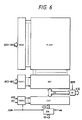
- Fig. 6 shows a block diagram of another embodiment of the semiconductor memory device according to the present invention.
- the circuit of the embodiment in Fig. 5 needs to be provided with the two Y-selector circuits YSEL1 and YSEL2, and therefore enlarges in scale to that extent.
- the writing and reading Y-selector circuits can be made common.
- column switching circuits are constructed in two stages. More specifically, the first column switches CW1 which are disposed in correspondence with the data lines of a memory array M-ARY operate to select the data lines in 32-bit unit (in the number of thirty-two). A first Y-decoder circuit YDCR1 is provided in correspondence with such column switches CW1.
- the Y-decoder circuit YDCR1 decodes address signals AY2 - AY n of upper bits except address signals AY0 and AY1 of the lowest two bits, and forms select signals to be supplied to the first column switches CW1.
- Laid on the output side of the first column switches CW1 are first common data lines CD1 which transmit information of 32 bits.
- the first common data lines CD1 are, on one hand, coupled to the input terminals of a read circuit RA, through which the information can be read in the unit of 32 bits at one time for another circuit (such as CPU) formed on the same chip as that of the EPROM.
- the read circuit RA has its operation controlled by the control signal epm described before, and it is brought into the operating state thereof when the EPROM is accessed from the circuit formed on the same chip as that of this EPROM.
- the first common data lines CD1 are, on the other hand, coupled to the second column switches CW2 in order to perform a write operation (including a read operation for verification) in 8-bit unit.
- the second column switches CW2 operate to select every eight of the thirty-two common data lines CD1. More specifically, the second column switches CW2 select eight common data lines from among the first common data lines CD1 numbering thirty-two and couple the selected lines to second common data lines CD2 consisting of eight signal lines, in accordance with select signals which are formed by a second Y-decoder circuit YDCR2 receiving the address signals AY0 and AY1 of the lowest two bits.
- the second common data lines CD2 are coupled to a writing input/output circuit IOB which transfers data in 8-bit unit.
- the second decoder YDCR2 falls into the operating state thereof when the control signal epm is at the high level. On this occasion, it decodes the address signals AY0 and AY1.
- the input/output circuit IOB is also brought into the operating state thereof when the control signal is at the high level. The selection of either the write operation or the read operation is determined by the control signal we.
- the second and first Y-decoder circuits YDCR2 and YDCR1 are brought into the operating states, and write data items of 8 bits supplied from the EPROM writer disposed outside the LSI are transmitted to the memory array M-ARY through the second column switches CW2 and first column switches CW1, whereby the write operation (including the read operation for the verify mode) in 8-bit unit can be performed.
- the second Y-decoder circuit YDCR2 is brought into the non-operating state thereof, and read signals of 32 bits delivered onto the first common data lines CD1 are output through the read circuit RA.
- the first Y-decoder circuit YDCR1 and the first column switches CW1 can be used for both the write mode and the read mode as described above, the simplification of the Y-address selector circuitry becomes possible.
- Fig. 7 shows a block diagram of another embodiment of the EPROM circuit according to the present invention.
- a memory array M-ARY is divided into two memory blocks.
- One of the memory blocks is constructed of unit memory blocks M100 thru M131.
- Each of the unit memory blocks M100 - M131 is constructed of pluralities of word lines and data lines, and nonvolatile storage elements disposed at the intersection points of the word lines and data lines.
- the word lines are laid in common. Therefore, an X-decoder circuit XDCR1 for selecting the word lines is constructed of a single circuit.
- Two, column switching circuits are disposed in correspondence with the thirty-two memory blocks M100-M131.
- the column switches WCW1 for writing data select the data lines in such a manner that one data line is selected from each of four sets which consist of eight of the unit memory blocks M100 thru M107, M108 - M115, M116 - M123 and M124 - M131, respectively. That is, the data lines numbering eight are selected.
- the selected data lines are respectively connected with eight signal lines D0 thru D7 corresponding to a write circuit WA.
- a Y-decoder circuit YDCR1W for writing data is provided.
- the write circuit WA corresponds to the input/output circuit IOB described before, and transfers signals (data items) between it and a universal EPROM writer.
- the thirty-two unit memory blocks M100 - M131 are furnished with the column switching circuit RCW1 for reading data.
- This column switching circuit RCW1 selects the data lines totaling thirty-two in such a manner that one data line is selected from among the plurality of data lines in each of the unit memory blocks M100 - M131, and it couples the selected data lines to thirty-two output signal lines X32, respectively.
- the read circuit RA (not shown) as described before is connected to the output signal lines X32.
- one memory block constructed of the thirty-two unit memory blocks M100 - M131 can be subjected to the write operation (including the verify/read mode) in 8-bit unit by the use of the X-decoder circuit XDCR1 and the writing decoder circuit YDCR1W as well as the column switching circuit WCW1 corresponding thereto.
- the memory block constructed of the thirty-two unit memory blocks M100 - M131 can be subjected to the operation of reading data for the circuit formed on the same chip as that of the EPROM, in 32-bit unit by the use of the X-decoder circuit XDCR1 and a reading decoder circuit YDCR1R as well as the column switching circuit RCW1 corresponding thereto.
- the other memory block is constructed of unit memory blocks M200 thru M212 similar to the foregoing. Although not especially restricted, the other memory block constructed of these unit memory blocks M200 - M212 is furnished with an X-decoder circuit XDCR2 which serves to select word lines extended in common. Thus, the two memory blocks can be selected with their own X-address signals.
- Two, column switching circuits are disposed in correspondence with the memory block constructed of the thirteen unit memory blocks M200 - M212, likewise to those of the memory block constructed of the thirty-two unit memory blocks M100 - M131.
- the column switching circuit WCW2 for writing data selects data lines in such a manner that one data line is selected from each of eight of the thirteen unit memory blocks M200 - M212, for example, either the unit memory blocks M200 - M207 or M208 - M215 (in which the unit memory blocks M213 - M215 are not actually provided and are therefore regarded as virtual unit memory blocks), and it couples the eight selected data lines to the eight signal lines D0 - D7 corresponding to the write circuit WA described before, respectively.
- the thirteen unit memory blocks M200 thru M212 are furnished with the column switching circuit RCW2 for reading data.
- This column switching circuit RCW2 selects the data lines in such a manner that one of the plurality of data lines in each of the unit memory blocks M200 - M212 is selected, and it couples the selected data lines to thirteen output signal lines X13, respectively.
- the read circuit RA (not shown) as described before is connected to the output signal lines X13.
- the other memory block constructed of the thirteen unit memory blocks M200 - M212 can be subjected to the write operation (including the verify/read mode) in 8-bit unit by the use of the X-decoder circuit XDCR2 and the writing decoder circuit YDCR2W as well as the column switching circuit WCW2 corresponding thereto.
- the memory block constructed of the thirteen unit memory blocks M200 - M212 can be subjected to the read operation in 13-bit unit by the use of the X-decoder circuit XDCR2 and a reading decoder circuit YDCR2R as well as the column switching circuit RCW2 corresponding thereto.
- the write circuit WA is made common to the plurality of memory blocks having the unequal numbers of unit memory blocks, thereby making it possible that, while data items are written into the respective memory blocks in 8-bit unit, data items are read out of the respective memory blocks in the units of any desired numbers of bits.
- the write circuit WA is controlled by the control signal we and is brought into the operating state thereof in the write operation.
- the Y-decoders YDCR1W and YDCR2W are controlled by the control signal epm, and the Y-decoders YDCR1R and YDCR2R are controlled by the control signal epm in this embodiment as in the foregoing embodiments.
- the Y-decoders YDCR1W and YDCR2W are brought into the operating states thereof in the write operation (including the verify operation), whereas the Y-decoders YDCR1R and YDCR2R are brought into the operating states thereof in the read operation.
- the operations of writing the information items into the individual EPROM areas can be performed by a single universal writer. It is also permitted that a circuit (for example, CPU) formed on the same chip as that of the EPROM reads information of required bit configuration from the EPROM at will.
- a circuit for example, CPU
- the data lines of the memory array M-ARY may well be divided into a plurality of blocks so as to read data items or program words having a plurality of sorts of numbers of bits.
- the word lines of the two memory blocks may well be made common so as to perform a select operation by means of a single X-address decoder.
- the number of the memory blocks is set at a number conforming to the sorts of data, program words, etc. to be stored.
- the external device for accessing the EPROM built in the LSI is not restricted to the EPROM writer, but it may well be any of another microcomputer, etc.
- the invention made by the inventors has been principally described as to the application thereof to a single-chip microcomputer with a built-in EPROM as forms the background field of utilization.
- the present invention is not restricted thereto, but it can also be utilized for an LSI for communications having a built-in EPROM, an LSI in which an EEPROM or RAM being electrically erasable or a readable and writable memory other than the EPROM is built, and a semiconductor memory in the form of a single product.
- an on-chip memory is a RAM
- a kind of data conversion operation may well be executed by the RAM in such a way that signals are written into the RAM through a signal bus configured of, for example, 8 bits (bytes), and that the signals are read out of the RAM as data which is configured of a plurality of bytes and endowed with a specified significance through the combination of the signals.
Landscapes
- Engineering & Computer Science (AREA)
- Microelectronics & Electronic Packaging (AREA)
- Read Only Memory (AREA)
- Microcomputers (AREA)
Abstract
Description
- The present invention relates to a semiconductor integrated circuit device. It relates to techniques which may be applied with advantage to an address change-over system in a semiconductor memory device (hereinafter referred to as a "memory"). By way of example, the techniques may be utilized in a large-scale integrated circuit (LSI) which has a built-in rewritable Read Only Memory (ROM).
- In a conventional LSI such a single-chip microcomputer having a built-in Erasable Programmable ROM (EPROM) in which floating-gate avalanche injection MOS (FAMOS) FETs are used as storage elements, addresses are common to the operation of reading data from within the EPROM and the operation of writing data into the EPROM by means of an EPROM writer, and both the reading and writing of the data are performed, for example, in an 8-bit unit. Refer for example, to the "Hitachi Microcomputer Data Book, 8-bit Single Chip" p. 823 - p. 861, issued by Hitachi, Ltd., in August 1984.
- With enhancements in the functions of the single-chip microcomputer, the internal data bus of the LSI is sometimes configured of 16 bits so that data can be read out of the EPROM in word (16-bit) unit.
- In this case, unless there is some change, data cannot be written into the built-in EPROM by the use of the conventional EPROM writer for 8 bits. It is accordingly necessary newly to develop an EPROM writer for 16 bits or to cope with the situation through software so that the data can be written using the EPROM writer for 8 bits.
- However, the method in which a new EPROM writer for 16 bits is developed is costly. On the other hand, the method in which the situation is resolved by software has the drawback that the time required for the writing operation is increased.
- Moreover, when the capacity of the internal data bus of the LSI having a built-in EPROM is to be enlarged into 32 bits, it will be necessary to develop another EPROM writer or to alter the software.
- The present invention therefore seeks to provide a memory which is suited to be built in an LSI.
- The present invention seeks to make it possible for data items to be read and written easily and smoothly without altering an external device (for example, the construction of a writer) or preparing software for an external device even when the number of bits of data to be read out of a memory built in an LSI differs between in case of accessing the memory inside the LSI and in case of accessing it from outside the LSI.
- Therefore, in a first aspect, the present invention proposes that there is address change means for changing a bit order between address signals which are supplied when the memory area is to be accessed from outside the integrated circuit device and address signals which are supplied when the memory area is to be accessed inside the integrated circuit device.
- Therefore an address input portion may be provided with means for changing-over address signals so that the order of the signals to be input to an address decoder can be changed in conformity with an external control signal.
- According to the expedient described above, addresses are changed-over in, for example, the way that when an EPROM inside an LSI is to be accessed from outside the LSI, the address signals having been input are supplied unchanged to the EPROM, whereas when the EPROM is to be accessed within the LSI, the address signals are supplied to the EPROM after each of the bits thereof is shifted one bit to the upper bit side. Thus, when the EPROM from which data is read in 16-bit unit in the access operation within the LSI is to be accessed by an EPROM writer from outside the LSI, data can be read and written in 8-bit unit, whereby the objects can be accomplished.
- Another construction of the present invention consists in disposing a reading output circuit which reads data in the unit of the number of bits different from that of a writing input circuit.
- Thus in a second aspect the present invention may further propose that the device has an input circuit which serves to write data into said memory area, and an output circuit which serves to read data in a bit unit different from that of the writing input circuit.
- That is, the present invention makes it possible to change-over the matrix arrayals of the EPROM at will, whereby even when the configuration of the internal data bus of the LSI is altered, data can be written using the existing EPROM writer as it is.
- Embodiments of the invention will now be described in detail, by way of example, with reference to the accompanying drawings, in which:
- Fig. 1 is a block diagram showing an embodiment of a single-chip microcomputer which includes an EPROM;
- Fig. 2A is a block diagram showing an embodiment of the EPROM according to the present invention included in a single-chip microcomputer;
- Fig. 2B is a block diagram for explaining the EPROM in Fig. 2A;
- Fig. 3 is a circuit diagram showing another embodiment of an address input portion in the EPROM;
- Fig. 4 is a circuit diagram showing still another embodiment of the address input portion of the EPROM;
- Fig. 5 is a block diagram showing another embodiment of an EPROM circuit according to the present invention;
- Fig. 6 is a block diagram showing still another embodiment of the EPROM circuit according to the present invention; and
- Fig. 7 is a block diagram showing yet another embodiment of the EPROM circuit according to the present invention.
- Shown in Fig. 1 is an embodiment in the case where the present invention is applied to a single-chip microcomputer which uses an EPROM as an on-chip ROM. In the figure, various circuit blocks enclosed with a dot-and-dash line are formed on a single semiconductor substrate by well-known techniques for semiconductor integrated circuits. That is, the circuit blocks are formed on a single chip.
- Although not especially restricted, the single-chip microcomputer of this embodiment comprises a microprocessor (hereinbelow, termed "CPU") 1 which controls the internal execution unit etc. thereof in accordance with programs, a
ROM 2 in which the operation programs of theCPU 1, etc. are stored, a RAM (random access memory) 3 which principally offers the working space of theCPU 1, a timer circuit 4, a serial communication interface circuit (SCI) 5 which performs the serial communications between the microcomputer and external devices, and an input/output port 6. These constituent circuits are interconnected through aninternal address bus 7a and aninternal data bus 7b. - In addition, a
control circuit 8 which determines the operation mode of the microcomputer and forms internal control signals corresponding thereto on the basis of a control signal supplied from outside is provided in the chip. - Although not especially restricted, the
CPU 1 is constructed of a program counter in which the address of an instruction or data to be read out next is held, an instruction register into which the instructions of a program are fetched in order, a control portion which is made of a random logic circuit or a micro-ROM storing microprograms and which forms a control signal corresponding to the instruction fetched in the instruction register, and the execution unit which includes various registers such as accumulators, an ALU (arithmetic/logic unit), etc. - In this embodiment, the on-
chip ROM 2 is constructed of a rewritable EPROM. This EPROM 2 is connected to thedata bus 7b of 16 bits, and when accessed with address signals A₀ - An-1 provided from theCPU 1, it delivers data of 16 bits onto thedata bus 7b. On the other hand, theEPROM 2 can also be accessed through the input/output port 6 by any of an EPROM writer, etc. which are disposed outside the single-chip microcomputer. Indicated by symbols D₀ - D₇ in Fig. 1 are eight data input/output terminals. In the single-chip microcomputer of this embodiment, when a write mode for theEPROM 2 is designated by mode switching control signals MODE1 and MODE2 applied to thecontrol circuit 8, data is read out of theEPROM 2 and delivered onto thedata bus 7b in 8-bit unit with address signals A₀ - An which are supplied from the external EPROM writer. In this case, the data output terminals of the EPROM connected to, for example, the upper 8 bits of thedata bus 7b are connectible also to the lower 8 bits thereof. In the write mode of the EPROM, the upper 8 bits in the 16-bit data bus 7b are rendered floating, and data is written into theEPROM 2 or is read therefrom by the use of only the lower 8 bits. In order to permit the change-over between the numbers of bits of data as described above, an EPROM input/output portion 2a which is constructed of an address change-over circuit, sense amplifiers, a train of column switches, etc. to be described later is provided at the connection part of theEPROM 2 with theaddress bus 7a as well as thedata bus 7b. - Fig. 2A shows an embodiment of the practicable circuit of the
EPROM 2 which is included in the single-chip microcomputer. - Although not especially restricted, the EPROM of this embodiment has an address decoder DCR supplied with complementary address signals a₁,
a₁ - an,an which are formed through address buffers ADB₁ - ADBn receiving the address signals A₀ - An. Here, the address signals A₀ can be supplied to a first address buffer ADB₀ and the second address buffer ADB₁ through respective switch MOSFETs Q₁₀ and Q₂₁. In addition, the address signal A₁ can be supplied to the second address buffer ADB₁ and the third address buffer ADB₂ through respective switch MOSFETs Q₁₁ and Q₂₂. Thenceforth, connections are similarly made so that each of the address signals A₂ - An-1 can be supplied to the two address buffers ADBi and ADBi+1 through one pair of corresponding switch MOSFETs Q1i and Q2(i+1) (i = 1, 2, ..., n - 1). The address signal An can be supplied to only the address buffer ADBn, and it is not supplied to any of the address buffers when the switch MOSFET Q2n is turned "on" so as to supply the address signal An-1 to the address buffer ADBn. - Each pair of switch MOSFETs Q1i and Q2(i+1) have either of them brought into the "on" state by change-over signals epm and
epm from the control circuit (CONT) 8. The address decoder DCR forms select signals for the word lines W₁, W₂, .... of a memory array M-ARY and select signals for column switching MOSFETs Q₃₁ - Q3m on the data lines DL₀₁ - DL0m, .... and DL₇₁ - DL7m of the memory array M-ARY in accordance with the address signals which have been selectively supplied. - The data lines DL₀₁ - DL0m, .... and DL₇₁ - DL7m are respectively connected to the corresponding ones of eight common data lines CD₀ - CD₇ through the column selecting switch MOSFETs Q₃₁ - Q3m which receive the select signals formed by the address decoder DCR. In addition, the output signals of writing data input circuits DIB₀ - DIB₇ which receive write signals applied from corresponding read/write terminals I/O₀ - I/O₇ are respectively supplied to write circuits PG₁₀ - PG₁₇ through switch MOSFETs Q₅₁, and write signals boosted to a write voltage Vpp are supplied to the common data lines CD₀ - CD₇. The output signals of the input circuits DIB₀ - DIB₇ can also be supplied to the common data lines of another memory mat through MOSFETs Q₅₂ as well as write circuits PG₂₀ - PG₂₇. Sense amplifiers SA₀ - SA₇ are respectively connected to the common data lines CD₀ - CD₇, and read data items amplified by the sense amplifiers SA₀ - SA₇ are delivered onto the internal data bus of the LSI through corresponding data buffers LDO₀ - LDO₇ which are dedicated to the reading. Further, the outputs of the sense amplifiers SA₀ - SA₇ are supplied to output buffers DOB₀ - DOB₇ through switch MOSFETs Q₄₁ so as to be deliverable to the read/write terminals I/O₀ - I/O₇, respectively. Moreover, the output buffers DOB₀ - DOB₇ are respectively supplied with the corresponding ones of the eight sense amplifiers of the other memory mat through switch MOSFETs Q₄₂, alternatively to the output signals of the sense amplifiers SA₀ - SA₇.
- In this embodiment, as illustrated in Fig. 2B, the output terminals of the data buffers LDO₀ - LDO₇ and the read/write terminals I/O₀ - I/O₇ are respectively connected in common to the signal lines b₀ - b₇ of the lower eight bits in the
data bus 7b. It is also possible, however, that the data buffers LDO₀ - LDO₇ are connected to the internal data bus, while the read/write terminals I/O₀ - I/O₇ are connected to the external terminals of the IC. Besides, in this embodiment, the memory mats each having the construction of input/output in 8-bit unit as described above are disposed in the number of two, and the two memory mats M-M₁ and M-M₂ constitute one memory array M-ARY. Each memory mat M-M₁ (M-M₂) is furnished with the eight sense amplifiers SA₀ - SA₇ (SA₈ - SA₁₅), so that 8-bit data items can be read out in parallel as a whole. In Fig. 2A, only one M-M₁ of the two memory mats M-M₁ and M-M₂ is depicted. By the way, regarding the other memory mat M-M₂ not depicted in Fig. 2A, only the eight sense amplifiers SA₈ - SA₁₅ and succeeding data buffers LDO₈ - LDO₁₅ which are disposed in correspondence with this memory mat M-M₂ are connected as illustrated in Fig. 2A. The memory mat M-M₂ is connected to the signal lines b₈ - b₁₅ of the upper 8 bits of theinternal data bus 7b through these sense amplifiers SA₈ - SA₁₅ and data buffers LDO₈ - LDO₁₅, so that when the switch MOSFETs Q₄₂ are brought into their "on" states, the output signals of the sense amplifiers SA₈ - SA₁₅ are respectively supplied to the output buffers DOB₀ - DOB₇ shown in Fig. 2A. Thus, the read data items of the memory mat M-M₂ are delivered onto the signal lines b₀ - b₇ of the lower 8 bits of thedata bus 7b replacing the upper 8 bits b₈ - b₁₅ thereof. In this embodiment, each of the data buffers LDO₀ - LDO₁₅ and the output buffers DOB₀ - DOB₇ is constructed of a tristate buffer. Each of the data buffers LDO₀ - LDO₁₅ has its operation controlled by the control signalepm , while each of the output buffers DOB₀ - DOB₇ has its operation controlled by the control signal epm. More specifically, when the control signalepm is at its high level, the data buffers LDO₀ - LDO₁₅ deliver output signals conforming to the input signals thereof through the output nodes thereof. In contrast, when the control signalepm is at its low level, the data buffers LDO₀ - LDO₁₅ bring the output nodes into the high impedance states thereof irrespective of the input signals. Meanwhile, when the control signal epm is at its high level, the output buffers DOB₀ - DOB₇ deliver output signals conforming to the input signals thereof through the output nodes thereof. In contrast, when the control signal epm is at its low level, the output buffers DOB₀ - DOB₇ bring the output nodes into the high impedance states thereof irrespective of the input signals. As will be described later, the control signal epm is set at the high level when theEPROM 2 is to be accessed by an external device (for example, EPROM writer). On this occasion, the control signalepm is set at the low level. On the other hand, when theEPROM 2 is to be accessed by any device inside the LSI, such as theCPU 1, the control signalepm is set at the high level. On this occasion, the control signal epm is set at the low level. In a case where theCPU 1 within the LSI has accessed theEPROM 2 in this way, the data items of theEPROM 2 are transmitted to thedata bus 7b (signal lines b₀ - b₁₅) through the data buffers LDO₀ - LDO₁₅. Besides, in a case where theEPROM 2 has been accessed by the external device of the LSI, the data items of theEPROM 2 are transmitted to thedata bus 7b (signal lines b₀ - b₇) through the output buffers DOB₀ - DOB₇. - In this embodiment, each of the buffers LDO₀ - LDO₁₅ and DOB₀ - DOB₇ is constructed of the tristate buffer as described before. Alternatively, it is allowed to employ an arrangement in which MOSFETs to be switched and controlled by the control signal
epm are connected between the output nodes of the respective buffers LDO₀ - LDO₁₅ and thedata bus 7b, while MOSFETs to be switched and controlled by the control signal epm are connected between the output nodes of the respective buffers DOB₀ - DOB₇ and thedata bus 7b. - In Fig. 2B, for the brevity of the illustration, the change-over circuits constructed of the switch MOSFETs Q₄₁ and Q₄₂ are denoted by OSi (i = 0 - 7), and the change-over circuits constructed of the switch MOSFETs Q₅₁ and Q₅₂ are denoted by ISi (i = 0 - 7).
- Further, although not especially restricted, the LSI of this embodiment is furnished with the input terminals of the mode switching control signals MODE1 and MODE2 in addition to those of a program control signal
PGM , an out signalOE and a chip enable signalCE . The control circuit CONT (8) forms internal control signals we, oe, ce, epm,epm etc. for the circuit blocks inside the LSI, on the basis of the aforementioned control signals. Vpp indicates the write voltage referred to before. Among the internal control signals which are output from the control circuit CONT, the signal we is formed on the basis of the external control signalsPGM andCE by way of example, and it affords a timing for activating the data input circuits DIBi (i = 0 - 7). In addition, the internal control signals ce and oe are formed on the basis of the external control signalsOE andCE , and they afford timings for activating the sense amplifiers SAi (i = 0 - 15) and the data buffers LDOi (i = 0 - 15) as well as the output buffers DOBi (i = 0 - 7), respectively, though no special restriction is meant. In Figs. 2A and 2B, the supply of the control signal oe to these buffers is omitted for the brevity of the illustration. Further, the internal control signals epm andepm are principally formed on the basis of the mode switching control signals MODE1 and MODE2 supplied from outside, and they turn "on" either of the switch MOSFETs Q₁₀ - Q1n and Q₂₁ - Q2n as the address change-over means and afford a timing for activating the address buffers ADB₀ - ADBn. - The LSI of this embodiment having the built-in EPROM has the EPROM write mode designated by the mode switching control signals MODE1 and MODE2 when the EPROM writer is connected thereto. Thus, the internal control signal epm is set at the high level, and the internal control signal
epm at the low level. Consequently, the switch MOSFETs Q₁₀ - Q1n are brought into the "on" states, and the switch MOSFETs Q₂₁ - Q2n into the "off" states. Thus, the address signals A₀ - An supplied from the external device (EPROM writer) not shown are respectively input to the address buffers ADB₀ - ADBn, to form the internal address signals a₀ - an anda₀ -an . On the basis of the signals a₁ - an anda₁ -an among these internal address signals, one of the word lines in the memory array M-ary is selected, and the sixteen data lines are connected to the sense amplifiers SAi (i = 0 - 15) as well as the write circuits PGi (i = 10 - 17, 20 - 27). Concurrently, either the groups of switch MOSFETs Q₄₁ and Q₅₁ or Q₄₂ and Q₅₂ are brought into the "on" states by the internal address signals a₀ anda₀ which are output from the address buffer ADB₀. As a result, data items are written into the memory array M-ARY through the terminals I/O₀ - I/O₇ in 8-bit unit and in parallel by the use of the EPROM writer. Reading for verification is also executed. - On the other hand, when a normal operation mode (of at least two sorts) in which the internal circuit (for example, EPROM 2) is put under the control of the
CPU 1 is designated by the mode switching control signals MODE1 and MODE2 supplied from outside, the internal signal epm is set at the low level, and the internal signalepm is set at the high level. Thus, the address changing-over MOSFETs Q₁₀ - Q1n are brought into the "off" states, and those Q₂₁ - Q2n into the "on" states. Consequently, the address signals A₀ - An-1 supplied from the circuit inside the LSI , such asCPU 1, are respectively supplied to the address buffers ADB₁ - ADBn. That is, the address signals which are shifted one bit to the upper bit side with respect to the address signals in the EPROM writer mode are input to the address buffers of theEPROM 2. On this occasion, the address buffer ADB₀ is controlled by the internal signals epm andepm to have both the internal address signals a₀ anda₀ fixed to the low level. Thus, the sixteen data lines in the memory array M-ARY are respectively connected to the sixteen sense amplifiers SAi (i = 0 - 15), and data items of 16 bits are output from the data buffers LDOi (i = 0 - 15) onto theinternal data bus 7b. On this occasion, the output buffers DOBi, write circuits PGi and input buffers DIBi are brought into the non-operating states thereof by the internal control signals oe and we though no special restriction is intended. - In this manner, in the single-chip microcomputer of the embodiment, the number of bits of the input/output data of the EPROM, namely, the number of bits of the data items to be input/output in parallel can be changed-over between 8 bits and 16 bits in the modes of the EPROM designated by the mode switching control signals MODE1 and MODE2 externally supplied, namely, in the mode of writing data into the EPROM and the normal mode (read mode except the verify mode). Thus, even when the
internal data bus 7b is configured of 16 bits (bits or signal lines b₀ - b₁₅), data can be written into theEPROM 2 by the use of the EPROM writer for 8 bits. - Although the above embodiment has referred to the case of the
internal data bus 7b configured of 16 bits, the present invention can also be applied to a case of an internal data bus configured of 32 bits by dividing the memory array into four memory mats by way of example. - Shown in Fig. 3 is an example of arrangement of an address change-over portion in the case where the
internal data bus 7b is of 32 bits. As seen from the figure, in this embodiment, the address signals A₀ - An are shifted two bits to the upper bit side and then input to the address buffers ADB₂ - ADBn of theEPROM 2 in the normal mode by the switch MOSFETs Q₁₀- Q1n and Q₂₂ - Q2n which are respectively controlled by the internal control signals epm andepm . that is, the address signals A₀ - An-2 are respectively input to the address buffers ADB₂ - ADBn. Meanwhile, although not shown in the figure, the memory array M-ARY is constructed of four memory mats M-M₁ thru M-M₄, from or into each of which data items of 8 bits can be read or written in parallel. - When the EPROM writer has been connected, the address signals A₀ and A₁ are respectively supplied to the address buffers ADB₀ and ADB₁ and are used for the formation of select signals for selecting one of the four memory mats. That is, on this occasion, the address signals A₀ and A₁ are used as address signals for specifying one memory mat from among the memory mats M-M₁ thru M-M₄.
- In this embodiment, therefore, it becomes possible to change-over the input/output of data in 8-bit unit and the output of data in 32-bit unit (to change-over data).
- Incidentally, in both the foregoing embodiments, the MOSFETs Q₁₀ - Q1n and Q₂₂ - Q2n as the address change-over means are disposed at the stages preceding the respective address buffers ADB₀ - ADBn. Alternatively, the address change-over means may well be disposed at the stages succeeding these address buffers, in other words, between the address buffers and the address decoder DCR.
- Besides, in order to facilitate the description, the embodiments have been explained as constructing the memory array out of the plurality of mats. However, the construction of the memory array is not restricted thereto, but similar functional effects can be attained even with a memory array constructed of a single mat by applying the concept of the present invention thereto.
- Further, in the embodiments, the address signals are shifted to the upper bit side and then input to the address buffers ADB in the normal mode. However, the address input portion may well be constructed as shown in Fig. 4, whereby the address signals are shifted to the lower bit side and then input to the address buffers ADB in the mode of writing data into the
EPROM 2. - As thus far described, in the embodiments, the address input portion is furnished with the change-over means for the address signals, so that the order of the signals to be input to the address decoder DCR can be changed according to the external control signals. Thus, when the EPROM in the LSI is to be accessed from outside the LSI, the address signals having been input are supplied to the address decoder as they are, and when the EPROM is to be accessed within the LSI, the address is changed-over so that the respective bits of the address signals may be shifted one bit or two bits to the upper bit side and then supplied to the address decoder. Therefore, when the EPROM from which data is read in 16-bit unit or 32-bit unit in the internal access is to be accessed by the EPROM writer from outside, data is read or written in 8-bit unit. This produces the effect that data can be read and written easily and smoothly without altering any external device disposed outside the LSI or preparing software for the change-over of an address.
- By the way, in the embodiments, the groups of switch MOSFETs Q₄₁ and Q₄₂ for switching the mats are disposed between the sense amplifiers SA and the output buffers DOB, but they may well be interposed between the common data lines CD and the sense amplifiers SA.
- In addition, in the embodiments, the data buffers LDO₀ - LDO₇ and the output buffers DOB₀ - DOB₇ are separately disposed, but they may well be constructed of common buffers. By way of example, it is allowed to employ an arrangement in which the data buffers LDO₀ - LDO₇ are omitted and in which switching MOSFETs are additionally connected in parallel with the switching MOSFETs Q₄₁ and have their gates supplied with the control signal
epm so as to be switched and controlled. In this case, to the end of permitting the output buffers DOB₀ - DOB₇ to function also as the data buffers LDO₀ - LDO₇, the output buffers DOB₀ - DOB₇ are constructed of tristate buffers whose states are controlled by the signal oe, not by the signal epm. - Shown in Fig. 5 is a block diagram of another embodiment of the on-chip EPROM according to the present invention.
- A memory array M-ARY is so constructed that nonvolatile storage elements each having a stacked gate structure provided with a floating gate and a control gate are arranged in the shape of a matrix. The control gates of the stacked-gate transistors constituting the memory cells are coupled to word lines which are extended in the lateral direction as viewed in the figure. Besides, the drains of the stacked-gate transistors are coupled to data lines (bit lines or digit lines) which are extended in the vertical direction as viewed in the figure. The memory array M-ARY is formed of the memory matrix which is similar in construction to that of a known EPROM as stated above.
- The word line of the memory array M-ARY is brought into the selected state thereof by an X-selector circuit XSEL. The X-selector circuit XSEL is constructed of a decoder circuit which receives X-address signals AX and decodes them. In the write operation of the EPROM, the select level of the word line is rendered a high voltage level of, for example, about 12 V necessary for the write operation, whereas in the read operation, it is rendered a comparatively low level of, for example, about 5 V. Therefore, the X-selector circuit XSEL has the level conversion function of forming the different select levels in accordance with the write mode and the read mode of the EPROM.
- This embodiment is furnished with two Y-selector circuits YSEL1 and YSEL2 for writing and reading data in order that, while the write operation with a universal EPROM writer is realized, reading in the unit of any desired number of bits irrespective of the write operation may be permitted. More specifically, the data lines of the memory array M-ARY are subjected to select operations by the Y-selector circuit YSEL1 in the write mode. The writing Y-selector circuit YSEL1 is constructed of a decoder circuit (DCR) which receives writing Y-address signals AY1 and decodes them, and a column switching circuit (CW) which selects a plurality of data lines from within the memory array M-ARY in conformity with the outputs of the decoder circuit. By way of example, the universal EPROM writer not shown writes data in 8-bit (1-byte) unit, and hence, an input/output circuit IOB suited thereto is provided. In this case, the Y-selector circuit YSEL1 performs the select operation of selecting eight of the data lines of the memory array M-ARY and connecting them to the input/output circuit IOB in accordance with the designated Y-address signals AY1.
- The EPROM writer needs to perform the reading of the memory array M-ARY upon designating a verify mode or read mode for checking whether or not desired data has been written into the memory cells. To this end, the input/output circuit IOB is provided as stated above. For such write/read operations, column select signals which are formed by the decoder circuit (DCR) of the Y-selector circuit YSEL1 are brought for the write operation to a high voltage level of, for example, about 12 V so that write signals of high level can be transmitted to the data lines, and they are brought for the read operation to a comparatively low level of, for example, about 5 V. Therefore, the decoder circuit (DCR) has the level conversion function of forming the different select levels in accordance with the write mode and the read mode.
- Owing to the input/output circuit IOB and the writing Y-selector circuit YSEL1, the operation of writing data into the memory array M-ARY in 8-bit unit can be performed using the universal EPROM writer. Besides, the read operation in 8-bit unit is possible for the verify mode. In this embodiment, the reading Y-selector circuit YSEL2 is provided in order that data and information processing procedures such as microprograms, which are stored in the memory array M-ARY, may be read in the unit of any desired number of bits as stated before.
- The data lines of the memory array M-ARY are subjected to select operations by the Y-selector circuit YSEL2 when the read operation is performed by a circuit, such as CPU, formed on the same chip as that of the EPROM. The reading Y-selector circuit YSEL2 is constructed of a decoder circuit (DCR) which receives reading Y-address signals AY2 and decodes them, and a column selecting circuit (CW) which selects a plurality of data lines from within the memory array M-ARY in conformity with the output signals of the decoder circuit. By way of example, in a case where microprograms are stored in the memory array M-ARY and where each program word is configured of 32 bits (4 bytes), the Y-selector circuit YSEL2 suitably selects the data lines in 32-bit unit so as to perform the reading in 32-bit (4-byte) unit in conformity with the program word. That is, in accordance with the designated Y-address signals AY2, the Y-selector circuit YSEL2 selects thirty-two data lines from among the plurality of data lines of the memory array M-ARY, and it supplies the signals of the selected data lines to a read circuit RA so as to transmit them to, e. g., the microprogram decode circuit of the microprocessor CPU. The read circuit RA has sense amplifiers for amplifying (detecting) the data items on the selected data lines.
- Incidentally, in this case, the operation of selecting the word line in the memory array M-ARY is the same as in the case of the read operation in the verify mode described above.
- Since, in this embodiment, the two Y-selector circuits as data line selector circuits are arranged at both the ends of the data lines of the memory array M-ARY as illustrated in the figure, it is possible to perform the write operation employing the universal EPROM writer and the read operation in the unit of any desired number of bits irrespective of the bit unit of the write operation.
- The number of bits of data items which are written in parallel at one time in the write operation, and the number of bits of data items which are read in parallel at one time for the circuit (such as CPU) formed on the same chip as that of the EPROM are unequal as described above. For this reason, the write data items in the write operation are, of course, written into the EPROM as data having a specified significance or in the divided form of the program word. That is, data or a program word of 16-bit length is decomposed into two parts each having 8 bits, and data or a program word of 32-bit length is divided into four parts, whereupon such parts are written in byte unit by, e. g., the EPROM writer from outside.
- In the figure, symbol CTL denotes a control circuit which forms control signals epm,
epm and we respectively similar to the control signals epm,epm and we described in the foregoing embodiments. The Y-selector circuit YSEL1 and the input/output circuit IOB are brought into their operating states when the control signal epm is at the high level. In contrast, the Y-selector circuit YSEL2 and the read circuit RA are brought into their operating states when the control signalepm is at the high level. Besides, the input/output circuit IOB is instructed to perform either the write operation or the read operation by the signal we. - Fig. 6 shows a block diagram of another embodiment of the semiconductor memory device according to the present invention.
- The circuit of the embodiment in Fig. 5 needs to be provided with the two Y-selector circuits YSEL1 and YSEL2, and therefore enlarges in scale to that extent. In this embodiment shown in Fig. 6, the writing and reading Y-selector circuits can be made common.
- By way of example, in a case where, as in the preceding embodiment, the bit unit (the number of bits) of data items which are read for another circuit (such as CPU) formed in the identical LSI is set to be integral times (four times in the preceding example) relative to the bit unit (the number of bits) of data items which are supplied from outside the LSI in the write operation, column switching circuits are constructed in two stages. More specifically, the first column switches CW1 which are disposed in correspondence with the data lines of a memory array M-ARY operate to select the data lines in 32-bit unit (in the number of thirty-two). A first Y-decoder circuit YDCR1 is provided in correspondence with such column switches CW1. The Y-decoder circuit YDCR1 decodes address signals AY₂ - AYn of upper bits except address signals AY₀ and AY₁ of the lowest two bits, and forms select signals to be supplied to the first column switches CW1. Laid on the output side of the first column switches CW1 are first common data lines CD1 which transmit information of 32 bits. The first common data lines CD1 are, on one hand, coupled to the input terminals of a read circuit RA, through which the information can be read in the unit of 32 bits at one time for another circuit (such as CPU) formed on the same chip as that of the EPROM. The read circuit RA has its operation controlled by the control signal
epm described before, and it is brought into the operating state thereof when the EPROM is accessed from the circuit formed on the same chip as that of this EPROM. - The first common data lines CD1 are, on the other hand, coupled to the second column switches CW2 in order to perform a write operation (including a read operation for verification) in 8-bit unit. The second column switches CW2 operate to select every eight of the thirty-two common data lines CD1. More specifically, the second column switches CW2 select eight common data lines from among the first common data lines CD1 numbering thirty-two and couple the selected lines to second common data lines CD2 consisting of eight signal lines, in accordance with select signals which are formed by a second Y-decoder circuit YDCR2 receiving the address signals AY₀ and AY₁ of the lowest two bits.
- The second common data lines CD2 are coupled to a writing input/output circuit IOB which transfers data in 8-bit unit.
- The second decoder YDCR2 falls into the operating state thereof when the control signal epm is at the high level. On this occasion, it decodes the address signals AY₀ and AY₁. The input/output circuit IOB is also brought into the operating state thereof when the control signal is at the high level. The selection of either the write operation or the read operation is determined by the control signal we.
- Thus, in the write operation, the second and first Y-decoder circuits YDCR2 and YDCR1 are brought into the operating states, and write data items of 8 bits supplied from the EPROM writer disposed outside the LSI are transmitted to the memory array M-ARY through the second column switches CW2 and first column switches CW1, whereby the write operation (including the read operation for the verify mode) in 8-bit unit can be performed.
- In addition, when the read operation of the EPROM is performed by any circuit formed on the same chip as that of this EPROM, the second Y-decoder circuit YDCR2 is brought into the non-operating state thereof, and read signals of 32 bits delivered onto the first common data lines CD1 are output through the read circuit RA.
- Since, in this embodiment, the first Y-decoder circuit YDCR1 and the first column switches CW1 can be used for both the write mode and the read mode as described above, the simplification of the Y-address selector circuitry becomes possible.
- Fig. 7 shows a block diagram of another embodiment of the EPROM circuit according to the present invention.
- In this embodiment, a memory array M-ARY is divided into two memory blocks. One of the memory blocks is constructed of unit memory blocks M100 thru M131. Each of the unit memory blocks M100 - M131 is constructed of pluralities of word lines and data lines, and nonvolatile storage elements disposed at the intersection points of the word lines and data lines. For the thirty-two unit memory blocks, the word lines are laid in common. Therefore, an X-decoder circuit XDCR1 for selecting the word lines is constructed of a single circuit. Two, column switching circuits are disposed in correspondence with the thirty-two memory blocks M100-M131. The column switches WCW1 for writing data select the data lines in such a manner that one data line is selected from each of four sets which consist of eight of the unit memory blocks M100 thru M107, M108 - M115, M116 - M123 and M124 - M131, respectively. That is, the data lines numbering eight are selected. The selected data lines are respectively connected with eight signal lines D0 thru D7 corresponding to a write circuit WA. In order to realize such a select operation, a Y-decoder circuit YDCR1W for writing data is provided. The write circuit WA corresponds to the input/output circuit IOB described before, and transfers signals (data items) between it and a universal EPROM writer.
- The thirty-two unit memory blocks M100 - M131 are furnished with the column switching circuit RCW1 for reading data. This column switching circuit RCW1 selects the data lines totaling thirty-two in such a manner that one data line is selected from among the plurality of data lines in each of the unit memory blocks M100 - M131, and it couples the selected data lines to thirty-two output signal lines X32, respectively. Thus, the thirty-two data lines respectively corresponding to the thirty-two unit memory blocks are selected at one time. The read circuit RA (not shown) as described before is connected to the output signal lines X32.
- In this way, one memory block constructed of the thirty-two unit memory blocks M100 - M131 can be subjected to the write operation (including the verify/read mode) in 8-bit unit by the use of the X-decoder circuit XDCR1 and the writing decoder circuit YDCR1W as well as the column switching circuit WCW1 corresponding thereto. In addition, the memory block constructed of the thirty-two unit memory blocks M100 - M131 can be subjected to the operation of reading data for the circuit formed on the same chip as that of the EPROM, in 32-bit unit by the use of the X-decoder circuit XDCR1 and a reading decoder circuit YDCR1R as well as the column switching circuit RCW1 corresponding thereto.
- The other memory block is constructed of unit memory blocks M200 thru M212 similar to the foregoing. Although not especially restricted, the other memory block constructed of these unit memory blocks M200 - M212 is furnished with an X-decoder circuit XDCR2 which serves to select word lines extended in common. Thus, the two memory blocks can be selected with their own X-address signals.
- Two, column switching circuits are disposed in correspondence with the memory block constructed of the thirteen unit memory blocks M200 - M212, likewise to those of the memory block constructed of the thirty-two unit memory blocks M100 - M131. The column switching circuit WCW2 for writing data selects data lines in such a manner that one data line is selected from each of eight of the thirteen unit memory blocks M200 - M212, for example, either the unit memory blocks M200 - M207 or M208 - M215 (in which the unit memory blocks M213 - M215 are not actually provided and are therefore regarded as virtual unit memory blocks), and it couples the eight selected data lines to the eight signal lines D0 - D7 corresponding to the write circuit WA described before, respectively. In this case, regarding the three virtual unit memory blocks M213 - M215, no column switches are disposed because signal lines to correspond thereto do not exist. Accordingly, in a write operation (including a verify/read mode) for the unit memory blocks M208 - M212, data items in 8-bit unit are supplied through the signal lines D0 - D7 from the write circuit WA, but those of the data items corresponding to the signal lines D5 - D7 are invalidated. In order to perform the select operation in this manner, a Y-decoder circuit YDCR2W for writing data is provided.
- The thirteen unit memory blocks M200 thru M212 are furnished with the column switching circuit RCW2 for reading data. This column switching circuit RCW2 selects the data lines in such a manner that one of the plurality of data lines in each of the unit memory blocks M200 - M212 is selected, and it couples the selected data lines to thirteen output signal lines X13, respectively. The read circuit RA (not shown) as described before is connected to the output signal lines X13.
- In this way, the other memory block constructed of the thirteen unit memory blocks M200 - M212 can be subjected to the write operation (including the verify/read mode) in 8-bit unit by the use of the X-decoder circuit XDCR2 and the writing decoder circuit YDCR2W as well as the column switching circuit WCW2 corresponding thereto. In addition, the memory block constructed of the thirteen unit memory blocks M200 - M212 can be subjected to the read operation in 13-bit unit by the use of the X-decoder circuit XDCR2 and a reading decoder circuit YDCR2R as well as the column switching circuit RCW2 corresponding thereto.
- As thus far described, the write circuit WA is made common to the plurality of memory blocks having the unequal numbers of unit memory blocks, thereby making it possible that, while data items are written into the respective memory blocks in 8-bit unit, data items are read out of the respective memory blocks in the units of any desired numbers of bits.
- In addition, the write circuit WA is controlled by the control signal we and is brought into the operating state thereof in the write operation.
- Although no special restriction is intended, the Y-decoders YDCR1W and YDCR2W are controlled by the control signal epm, and the Y-decoders YDCR1R and YDCR2R are controlled by the control signal
epm in this embodiment as in the foregoing embodiments. Thus, the Y-decoders YDCR1W and YDCR2W are brought into the operating states thereof in the write operation (including the verify operation), whereas the Y-decoders YDCR1R and YDCR2R are brought into the operating states thereof in the read operation. - With the construction of this embodiment, in a case where information items having significances different from each other, such as data and program words, are respectively configured of any desired unequal numbers of bits and are stored in the separate EPROM areas, the operations of writing the information items into the individual EPROM areas can be performed by a single universal writer. It is also permitted that a circuit (for example, CPU) formed on the same chip as that of the EPROM reads information of required bit configuration from the EPROM at will.
- Functional effects which are attained by the embodiments stated above, are as follows:
- (1) A writing input circuit, and a reading output circuit which reads data in bit unit differing from that of the writing input circuit are provided, thereby to adapt the writing input circuit to a universal EPROM writer, whereby efficient writing becomes possible, and also reading in the unit of any desired number of bits becomes possible.
- (2) Owing to the effect (1), a universal EPROM writer of 8 bits can be used for writing data into an on-chip EMPROM from which data is read in 16- or 32-bit unit in an internal operation, so that curtailment in a writing cost can be achieved.
- (3) Since the number of bits of read data can be set irrespective of a write operation, the storage capacity of the memory array of an EPROM can be efficiently used, and the substantial packaging density of the EPROM can be heightened.
- (4) Since the number of bits of read data can be set as desired, a semiconductor integrated circuit device having an information processing function, such as a single-chip microcomputer with a built-in EPROM, can be fabricated into multifarious systems.
- Although, in the above, the invention made by the inventors has been concretely described in conjunction with embodiments, it is needless to say that the present invention is not restricted to the foregoing embodiments, but that it can be variously altered within a scope not departing from the purport thereof. By way of example, in Fig. 5 or Fig. 6, the data lines of the memory array M-ARY may well be divided into a plurality of blocks so as to read data items or program words having a plurality of sorts of numbers of bits. Besides, in Fig. 7, the word lines of the two memory blocks may well be made common so as to perform a select operation by means of a single X-address decoder. In addition, the number of the memory blocks is set at a number conforming to the sorts of data, program words, etc. to be stored.
- Further, the external device for accessing the EPROM built in the LSI is not restricted to the EPROM writer, but it may well be any of another microcomputer, etc.
- In the above, the invention made by the inventors has been principally described as to the application thereof to a single-chip microcomputer with a built-in EPROM as forms the background field of utilization. However, the present invention is not restricted thereto, but it can also be utilized for an LSI for communications having a built-in EPROM, an LSI in which an EEPROM or RAM being electrically erasable or a readable and writable memory other than the EPROM is built, and a semiconductor memory in the form of a single product. In a case where an on-chip memory is a RAM, a kind of data conversion operation may well be executed by the RAM in such a way that signals are written into the RAM through a signal bus configured of, for example, 8 bits (bytes), and that the signals are read out of the RAM as data which is configured of a plurality of bytes and endowed with a specified significance through the combination of the signals.
Claims (10)
Applications Claiming Priority (4)
| Application Number | Priority Date | Filing Date | Title |
|---|---|---|---|
| JP174703/87 | 1987-07-15 | ||
| JP17470387A JP2682625B2 (en) | 1987-07-15 | 1987-07-15 | Semiconductor integrated circuit device |
| JP208145/87 | 1987-08-24 | ||
| JP20814587A JPS6452297A (en) | 1987-08-24 | 1987-08-24 | Semiconductor intetrated circuit with storing part |
Publications (3)
| Publication Number | Publication Date |
|---|---|
| EP0299697A2 true EP0299697A2 (en) | 1989-01-18 |
| EP0299697A3 EP0299697A3 (en) | 1990-12-05 |
| EP0299697B1 EP0299697B1 (en) | 1993-09-29 |
Family
ID=26496219
Family Applications (1)
| Application Number | Title | Priority Date | Filing Date |
|---|---|---|---|
| EP88306302A Expired - Lifetime EP0299697B1 (en) | 1987-07-15 | 1988-07-11 | Semiconductor integrated circuit device |
Country Status (5)
| Country | Link |
|---|---|
| US (3) | US4989185A (en) |
| EP (1) | EP0299697B1 (en) |
| KR (1) | KR970005409B1 (en) |
| DE (1) | DE3884492T2 (en) |
| HK (1) | HK176295A (en) |
Cited By (1)
| Publication number | Priority date | Publication date | Assignee | Title |
|---|---|---|---|---|
| EP0712133A1 (en) * | 1994-11-10 | 1996-05-15 | STMicroelectronics S.A. | Method of anticipated reading of a serial accessed memory and related memory |
Families Citing this family (17)
| Publication number | Priority date | Publication date | Assignee | Title |
|---|---|---|---|---|
| EP0299697B1 (en) * | 1987-07-15 | 1993-09-29 | Hitachi, Ltd. | Semiconductor integrated circuit device |
| US5511211A (en) * | 1988-08-31 | 1996-04-23 | Hitachi, Ltd. | Method for flexibly developing a data processing system comprising rewriting instructions in non-volatile memory elements after function check indicates failure of required functions |
| JP2793296B2 (en) * | 1989-11-10 | 1998-09-03 | 株式会社東芝 | Semiconductor device |
| US5323355A (en) * | 1991-01-22 | 1994-06-21 | Fujitsu Limited | Semiconductor memory device |
| JPH0540730A (en) * | 1991-08-06 | 1993-02-19 | Mitsubishi Electric Corp | Micro computer |
| JPH05324463A (en) * | 1992-05-18 | 1993-12-07 | Mitsubishi Electric Corp | Memory device and data processor using the same |
| JPH0628846A (en) * | 1992-07-09 | 1994-02-04 | Mitsubishi Electric Corp | Semiconductor memory |
| JP3218103B2 (en) * | 1992-12-25 | 2001-10-15 | 三菱電機株式会社 | Semiconductor storage device |
| US5854132A (en) * | 1994-11-29 | 1998-12-29 | Advanced Micro Devices, Inc. | Method for exposing photoresist |
| JPH08321173A (en) * | 1995-05-23 | 1996-12-03 | Mitsubishi Electric Corp | Semiconductor memory |
| DE69629925T2 (en) * | 1995-06-07 | 2004-07-22 | Intel Corporation, Santa Clara | VOLTAGE CIRCUIT FOR NEGATIVE VOLTAGES |
| US5903496A (en) * | 1997-06-25 | 1999-05-11 | Intel Corporation | Synchronous page-mode non-volatile memory with burst order circuitry |
| US6725316B1 (en) | 2000-08-18 | 2004-04-20 | Micron Technology, Inc. | Method and apparatus for combining architectures with logic option |
| KR100453737B1 (en) * | 2002-07-29 | 2004-10-20 | 삼성전자주식회사 | digital data storage device |
| JP2005285190A (en) * | 2004-03-29 | 2005-10-13 | Sanyo Electric Co Ltd | Memory |
| US7149119B2 (en) * | 2004-09-30 | 2006-12-12 | Matrix Semiconductor, Inc. | System and method of controlling a three-dimensional memory |
| TWI301270B (en) * | 2006-06-30 | 2008-09-21 | Winbond Electronics Corp | Semiconductor memory and circuit and method of decoding address for the same |
Citations (2)
| Publication number | Priority date | Publication date | Assignee | Title |
|---|---|---|---|---|
| EP0064801A2 (en) * | 1981-05-07 | 1982-11-17 | Atari Inc. | Bank switchable memory system |
| EP0210064A2 (en) * | 1985-07-22 | 1987-01-28 | General Instrument Corporation | Variable page ROM |
Family Cites Families (13)
| Publication number | Priority date | Publication date | Assignee | Title |
|---|---|---|---|---|
| US3691538A (en) * | 1971-06-01 | 1972-09-12 | Ncr Co | Serial read-out memory system |
| US4214302A (en) * | 1978-04-24 | 1980-07-22 | Texas Instruments Incorporated | Eight bit standard connector bus for sixteen bit microcomputer |
| FR2506530A1 (en) * | 1981-05-22 | 1982-11-26 | Thomson Csf | COHERENT RADIATION SOURCE GENERATING AN ADJUSTABLE SPREAD DIRECTION BEAM |
| US4520464A (en) * | 1982-06-01 | 1985-05-28 | Ncr Corporation | Transparent instruction word bus memory system |
| JPS59124092A (en) * | 1982-12-29 | 1984-07-18 | Fujitsu Ltd | Memory device |
| JPS60177498A (en) * | 1984-02-23 | 1985-09-11 | Fujitsu Ltd | Semiconductor storage device |
| JPS60200287A (en) * | 1984-03-24 | 1985-10-09 | 株式会社東芝 | Memory unit |
| DE3680371D1 (en) * | 1985-04-10 | 1991-08-29 | Nec Corp | STORAGE WITH SELECTABLE WORD LENGTH. |
| JPS61294562A (en) * | 1985-06-21 | 1986-12-25 | Mitsubishi Electric Corp | Semiconductor memory device |
| JPS635444A (en) * | 1986-06-25 | 1988-01-11 | Hitachi Ltd | Microprocessor |
| JP2511910B2 (en) * | 1986-11-11 | 1996-07-03 | 三菱電機株式会社 | Semiconductor memory device |
| EP0299697B1 (en) * | 1987-07-15 | 1993-09-29 | Hitachi, Ltd. | Semiconductor integrated circuit device |
| JP2865170B2 (en) * | 1988-07-06 | 1999-03-08 | 三菱電機株式会社 | Electronic circuit device |
-
1988
- 1988-07-11 EP EP88306302A patent/EP0299697B1/en not_active Expired - Lifetime
- 1988-07-11 DE DE88306302T patent/DE3884492T2/en not_active Expired - Fee Related
- 1988-07-12 KR KR1019880008644A patent/KR970005409B1/en not_active IP Right Cessation
- 1988-07-15 US US07/219,736 patent/US4989185A/en not_active Expired - Lifetime
-
1990
- 1990-12-04 US US07/621,643 patent/US5105389A/en not_active Expired - Lifetime
-
1993
- 1993-05-28 US US08/069,988 patent/US5335204A/en not_active Expired - Lifetime
-
1995
- 1995-11-16 HK HK176295A patent/HK176295A/en not_active IP Right Cessation
Patent Citations (2)
| Publication number | Priority date | Publication date | Assignee | Title |
|---|---|---|---|---|
| EP0064801A2 (en) * | 1981-05-07 | 1982-11-17 | Atari Inc. | Bank switchable memory system |
| EP0210064A2 (en) * | 1985-07-22 | 1987-01-28 | General Instrument Corporation | Variable page ROM |
Cited By (3)
| Publication number | Priority date | Publication date | Assignee | Title |
|---|---|---|---|---|
| EP0712133A1 (en) * | 1994-11-10 | 1996-05-15 | STMicroelectronics S.A. | Method of anticipated reading of a serial accessed memory and related memory |
| FR2726934A1 (en) * | 1994-11-10 | 1996-05-15 | Sgs Thomson Microelectronics | METHOD FOR ANTICIPATED READING OF MEMORY WITH SERIAL ACCESS AND MEMORY RELATED THERETO |
| US5663922A (en) * | 1994-11-10 | 1997-09-02 | Sgs-Thomson Microelectronics S.A. | Method for the anticipated reading of serial access memory, and memory pertaining thereto |
Also Published As
| Publication number | Publication date |
|---|---|
| US5335204A (en) | 1994-08-02 |
| EP0299697A3 (en) | 1990-12-05 |
| KR890002883A (en) | 1989-04-11 |
| KR970005409B1 (en) | 1997-04-16 |
| US4989185A (en) | 1991-01-29 |
| DE3884492T2 (en) | 1994-02-17 |
| US5105389A (en) | 1992-04-14 |
| EP0299697B1 (en) | 1993-09-29 |
| DE3884492D1 (en) | 1993-11-04 |
| HK176295A (en) | 1995-11-24 |
Similar Documents
| Publication | Publication Date | Title |
|---|---|---|
| EP0299697B1 (en) | Semiconductor integrated circuit device | |
| US5606532A (en) | EEPROM array with flash-like core | |
| US6088264A (en) | Flash memory partitioning for read-while-write operation | |
| US4780855A (en) | System for controlling a nonvolatile memory having a data portion and a corresponding indicator portion | |
| US5806070A (en) | Device and method for controlling solid-state memory system | |
| EP0914659B1 (en) | Combined program and data nonvolatile memory with concurrent program-read/data write capability | |
| US4610000A (en) | ROM/RAM/ROM patch memory circuit | |
| KR100466980B1 (en) | Nand flash memory device | |
| JP2002513181A (en) | Microcontroller including a single memory module having a data memory sector and a code memory sector and supporting simultaneous read / write access to both sectors | |
| TW355844B (en) | Non-volatile semiconductor memory device | |
| KR100463202B1 (en) | Pad and peripheral circuit layout in semiconductor device | |
| KR20080073544A (en) | Memory card and memory system having thereof | |
| US7649778B2 (en) | Method for accessing in reading, writing and programming to a NAND non-volatile memory electronic device monolithically integrated on semiconductor | |
| JPH11242632A (en) | Memory device | |
| US4040029A (en) | Memory system with reduced block decoding | |
| JP4731020B2 (en) | Semiconductor memory device, sector address conversion circuit, address conversion method, and method of using semiconductor memory device | |
| JP2020154584A (en) | Memory system | |
| US5257234A (en) | Semiconductor integrated circuit device | |
| US6400611B1 (en) | Independent asynchronous boot block for synchronous non-volatile memory devices | |
| JP2663651B2 (en) | Semiconductor memory integrated circuit | |
| US4831587A (en) | Memory address circuit having function of exchanging selected bits of address input | |
| KR100480653B1 (en) | Combined program and data nonvolatile memory with concurrent program-read/data write capability | |
| JPH0789439B2 (en) | Semiconductor integrated circuit device | |
| KR0166650B1 (en) | Microcomputer having multiplexible input/output port | |
| KR200155592Y1 (en) | Memory test circuit |
Legal Events
| Date | Code | Title | Description |
|---|---|---|---|
| PUAI | Public reference made under article 153(3) epc to a published international application that has entered the european phase |
Free format text: ORIGINAL CODE: 0009012 |
|
| 17P | Request for examination filed |
Effective date: 19880801 |
|
| AK | Designated contracting states |
Kind code of ref document: A2 Designated state(s): DE FR GB IT |
|
| D17P | Request for examination filed (deleted) | ||
| PUAL | Search report despatched |
Free format text: ORIGINAL CODE: 0009013 |
|
| AK | Designated contracting states |
Kind code of ref document: A3 Designated state(s): DE FR GB IT |
|
| R17P | Request for examination filed (corrected) |
Effective date: 19910521 |
|
| 17Q | First examination report despatched |
Effective date: 19920326 |
|
| GRAA | (expected) grant |
Free format text: ORIGINAL CODE: 0009210 |
|
| AK | Designated contracting states |
Kind code of ref document: B1 Designated state(s): DE FR GB IT |
|
| REF | Corresponds to: |
Ref document number: 3884492 Country of ref document: DE Date of ref document: 19931104 |
|
| ET | Fr: translation filed | ||
| ITF | It: translation for a ep patent filed | ||
| PLBE | No opposition filed within time limit |
Free format text: ORIGINAL CODE: 0009261 |
|
| STAA | Information on the status of an ep patent application or granted ep patent |
Free format text: STATUS: NO OPPOSITION FILED WITHIN TIME LIMIT |
|
| 26N | No opposition filed | ||
| REG | Reference to a national code |
Ref country code: GB Ref legal event code: IF02 |
|
| PGFP | Annual fee paid to national office [announced via postgrant information from national office to epo] |
Ref country code: FR Payment date: 20040623 Year of fee payment: 17 |
|
| PGFP | Annual fee paid to national office [announced via postgrant information from national office to epo] |
Ref country code: GB Payment date: 20040630 Year of fee payment: 17 |
|
| PGFP | Annual fee paid to national office [announced via postgrant information from national office to epo] |
Ref country code: DE Payment date: 20040903 Year of fee payment: 17 |
|
| PG25 | Lapsed in a contracting state [announced via postgrant information from national office to epo] |
Ref country code: IT Free format text: LAPSE BECAUSE OF NON-PAYMENT OF DUE FEES;WARNING: LAPSES OF ITALIAN PATENTS WITH EFFECTIVE DATE BEFORE 2007 MAY HAVE OCCURRED AT ANY TIME BEFORE 2007. THE CORRECT EFFECTIVE DATE MAY BE DIFFERENT FROM THE ONE RECORDED. Effective date: 20050711 Ref country code: GB Free format text: LAPSE BECAUSE OF NON-PAYMENT OF DUE FEES Effective date: 20050711 |
|
| PG25 | Lapsed in a contracting state [announced via postgrant information from national office to epo] |
Ref country code: DE Free format text: LAPSE BECAUSE OF NON-PAYMENT OF DUE FEES Effective date: 20060201 |
|
| GBPC | Gb: european patent ceased through non-payment of renewal fee |
Effective date: 20050711 |
|
| PG25 | Lapsed in a contracting state [announced via postgrant information from national office to epo] |
Ref country code: FR Free format text: LAPSE BECAUSE OF NON-PAYMENT OF DUE FEES Effective date: 20060331 |
|
| REG | Reference to a national code |
Ref country code: FR Ref legal event code: ST Effective date: 20060331 |