EP0299308B1 - Building element made from a velvet texture and method for its manufacture - Google Patents
Building element made from a velvet texture and method for its manufacture Download PDFInfo
- Publication number
- EP0299308B1 EP0299308B1 EP88110601A EP88110601A EP0299308B1 EP 0299308 B1 EP0299308 B1 EP 0299308B1 EP 88110601 A EP88110601 A EP 88110601A EP 88110601 A EP88110601 A EP 88110601A EP 0299308 B1 EP0299308 B1 EP 0299308B1
- Authority
- EP
- European Patent Office
- Prior art keywords
- webs
- intermediate webs
- component according
- component
- fabric
- Prior art date
- Legal status (The legal status is an assumption and is not a legal conclusion. Google has not performed a legal analysis and makes no representation as to the accuracy of the status listed.)
- Expired - Lifetime
Links
Images


Classifications
-
- D—TEXTILES; PAPER
- D06—TREATMENT OF TEXTILES OR THE LIKE; LAUNDERING; FLEXIBLE MATERIALS NOT OTHERWISE PROVIDED FOR
- D06M—TREATMENT, NOT PROVIDED FOR ELSEWHERE IN CLASS D06, OF FIBRES, THREADS, YARNS, FABRICS, FEATHERS OR FIBROUS GOODS MADE FROM SUCH MATERIALS
- D06M17/00—Producing multi-layer textile fabrics
-
- D—TEXTILES; PAPER
- D06—TREATMENT OF TEXTILES OR THE LIKE; LAUNDERING; FLEXIBLE MATERIALS NOT OTHERWISE PROVIDED FOR
- D06N—WALL, FLOOR, OR LIKE COVERING MATERIALS, e.g. LINOLEUM, OILCLOTH, ARTIFICIAL LEATHER, ROOFING FELT, CONSISTING OF A FIBROUS WEB COATED WITH A LAYER OF MACROMOLECULAR MATERIAL; FLEXIBLE SHEET MATERIAL NOT OTHERWISE PROVIDED FOR
- D06N7/00—Flexible sheet materials not otherwise provided for, e.g. textile threads, filaments, yarns or tow, glued on macromolecular material
-
- E—FIXED CONSTRUCTIONS
- E04—BUILDING
- E04C—STRUCTURAL ELEMENTS; BUILDING MATERIALS
- E04C2/00—Building elements of relatively thin form for the construction of parts of buildings, e.g. sheet materials, slabs, or panels
- E04C2/02—Building elements of relatively thin form for the construction of parts of buildings, e.g. sheet materials, slabs, or panels characterised by specified materials
- E04C2/10—Building elements of relatively thin form for the construction of parts of buildings, e.g. sheet materials, slabs, or panels characterised by specified materials of wood, fibres, chips, vegetable stems, or the like; of plastics; of foamed products
- E04C2/16—Building elements of relatively thin form for the construction of parts of buildings, e.g. sheet materials, slabs, or panels characterised by specified materials of wood, fibres, chips, vegetable stems, or the like; of plastics; of foamed products of fibres, chips, vegetable stems, or the like
-
- Y—GENERAL TAGGING OF NEW TECHNOLOGICAL DEVELOPMENTS; GENERAL TAGGING OF CROSS-SECTIONAL TECHNOLOGIES SPANNING OVER SEVERAL SECTIONS OF THE IPC; TECHNICAL SUBJECTS COVERED BY FORMER USPC CROSS-REFERENCE ART COLLECTIONS [XRACs] AND DIGESTS
- Y10—TECHNICAL SUBJECTS COVERED BY FORMER USPC
- Y10S—TECHNICAL SUBJECTS COVERED BY FORMER USPC CROSS-REFERENCE ART COLLECTIONS [XRACs] AND DIGESTS
- Y10S428/00—Stock material or miscellaneous articles
- Y10S428/902—High modulus filament or fiber
-
- Y—GENERAL TAGGING OF NEW TECHNOLOGICAL DEVELOPMENTS; GENERAL TAGGING OF CROSS-SECTIONAL TECHNOLOGIES SPANNING OVER SEVERAL SECTIONS OF THE IPC; TECHNICAL SUBJECTS COVERED BY FORMER USPC CROSS-REFERENCE ART COLLECTIONS [XRACs] AND DIGESTS
- Y10—TECHNICAL SUBJECTS COVERED BY FORMER USPC
- Y10T—TECHNICAL SUBJECTS COVERED BY FORMER US CLASSIFICATION
- Y10T428/00—Stock material or miscellaneous articles
- Y10T428/24—Structurally defined web or sheet [e.g., overall dimension, etc.]
- Y10T428/24025—Superposed movable attached layers or components
-
- Y—GENERAL TAGGING OF NEW TECHNOLOGICAL DEVELOPMENTS; GENERAL TAGGING OF CROSS-SECTIONAL TECHNOLOGIES SPANNING OVER SEVERAL SECTIONS OF THE IPC; TECHNICAL SUBJECTS COVERED BY FORMER USPC CROSS-REFERENCE ART COLLECTIONS [XRACs] AND DIGESTS
- Y10—TECHNICAL SUBJECTS COVERED BY FORMER USPC
- Y10T—TECHNICAL SUBJECTS COVERED BY FORMER US CLASSIFICATION
- Y10T428/00—Stock material or miscellaneous articles
- Y10T428/24—Structurally defined web or sheet [e.g., overall dimension, etc.]
- Y10T428/24058—Structurally defined web or sheet [e.g., overall dimension, etc.] including grain, strips, or filamentary elements in respective layers or components in angular relation
- Y10T428/24074—Strand or strand-portions
- Y10T428/24116—Oblique to direction of web
-
- Y—GENERAL TAGGING OF NEW TECHNOLOGICAL DEVELOPMENTS; GENERAL TAGGING OF CROSS-SECTIONAL TECHNOLOGIES SPANNING OVER SEVERAL SECTIONS OF THE IPC; TECHNICAL SUBJECTS COVERED BY FORMER USPC CROSS-REFERENCE ART COLLECTIONS [XRACs] AND DIGESTS
- Y10—TECHNICAL SUBJECTS COVERED BY FORMER USPC
- Y10T—TECHNICAL SUBJECTS COVERED BY FORMER US CLASSIFICATION
- Y10T428/00—Stock material or miscellaneous articles
- Y10T428/24—Structurally defined web or sheet [e.g., overall dimension, etc.]
- Y10T428/24058—Structurally defined web or sheet [e.g., overall dimension, etc.] including grain, strips, or filamentary elements in respective layers or components in angular relation
- Y10T428/24124—Fibers
-
- Y—GENERAL TAGGING OF NEW TECHNOLOGICAL DEVELOPMENTS; GENERAL TAGGING OF CROSS-SECTIONAL TECHNOLOGIES SPANNING OVER SEVERAL SECTIONS OF THE IPC; TECHNICAL SUBJECTS COVERED BY FORMER USPC CROSS-REFERENCE ART COLLECTIONS [XRACs] AND DIGESTS
- Y10—TECHNICAL SUBJECTS COVERED BY FORMER USPC
- Y10T—TECHNICAL SUBJECTS COVERED BY FORMER US CLASSIFICATION
- Y10T428/00—Stock material or miscellaneous articles
- Y10T428/24—Structurally defined web or sheet [e.g., overall dimension, etc.]
- Y10T428/24149—Honeycomb-like
-
- Y—GENERAL TAGGING OF NEW TECHNOLOGICAL DEVELOPMENTS; GENERAL TAGGING OF CROSS-SECTIONAL TECHNOLOGIES SPANNING OVER SEVERAL SECTIONS OF THE IPC; TECHNICAL SUBJECTS COVERED BY FORMER USPC CROSS-REFERENCE ART COLLECTIONS [XRACs] AND DIGESTS
- Y10—TECHNICAL SUBJECTS COVERED BY FORMER USPC
- Y10T—TECHNICAL SUBJECTS COVERED BY FORMER US CLASSIFICATION
- Y10T428/00—Stock material or miscellaneous articles
- Y10T428/24—Structurally defined web or sheet [e.g., overall dimension, etc.]
- Y10T428/24174—Structurally defined web or sheet [e.g., overall dimension, etc.] including sheet or component perpendicular to plane of web or sheet
- Y10T428/24182—Inward from edge of web or sheet
-
- Y—GENERAL TAGGING OF NEW TECHNOLOGICAL DEVELOPMENTS; GENERAL TAGGING OF CROSS-SECTIONAL TECHNOLOGIES SPANNING OVER SEVERAL SECTIONS OF THE IPC; TECHNICAL SUBJECTS COVERED BY FORMER USPC CROSS-REFERENCE ART COLLECTIONS [XRACs] AND DIGESTS
- Y10—TECHNICAL SUBJECTS COVERED BY FORMER USPC
- Y10T—TECHNICAL SUBJECTS COVERED BY FORMER US CLASSIFICATION
- Y10T428/00—Stock material or miscellaneous articles
- Y10T428/24—Structurally defined web or sheet [e.g., overall dimension, etc.]
- Y10T428/24802—Discontinuous or differential coating, impregnation or bond [e.g., artwork, printing, retouched photograph, etc.]
- Y10T428/2481—Discontinuous or differential coating, impregnation or bond [e.g., artwork, printing, retouched photograph, etc.] including layer of mechanically interengaged strands, strand-portions or strand-like strips
-
- Y—GENERAL TAGGING OF NEW TECHNOLOGICAL DEVELOPMENTS; GENERAL TAGGING OF CROSS-SECTIONAL TECHNOLOGIES SPANNING OVER SEVERAL SECTIONS OF THE IPC; TECHNICAL SUBJECTS COVERED BY FORMER USPC CROSS-REFERENCE ART COLLECTIONS [XRACs] AND DIGESTS
- Y10—TECHNICAL SUBJECTS COVERED BY FORMER USPC
- Y10T—TECHNICAL SUBJECTS COVERED BY FORMER US CLASSIFICATION
- Y10T428/00—Stock material or miscellaneous articles
- Y10T428/30—Self-sustaining carbon mass or layer with impregnant or other layer
Definitions
- the invention relates to a component based on velor fabric according to the features of the preamble of claim 1. Furthermore, a method for producing a component by resinification and subsequent curing of a fabric according to the features of the preamble of claim 12.
- resin-hardened fiber composite materials have found a wide range of applications, be it in the form of load-bearing structural elements or for the fulfillment of insulation tasks. With the greatest possible rigidity and compressive strength, the lowest possible weight is also sought for special cases, such as flight technology.
- a textile insulation element which consists of spaced layers and connected by means of intermediate webs.
- the fabric can be made of glass fiber. It is important that a component manufactured according to this has a certain flexibility. In terms of production, it is also important that the tissue is kept under tension during resinification.
- types of weave such as weft velvet and warp velvet are known.
- double velvet is created, in which the connecting webs between the layer-creating velor threads make a double shed formation.
- the length of the floating threads is adjustable so that longer or shorter web lengths are achieved.
- the center threads of the pile threads are then cut on a cutting bench.
- the present invention has set itself the task, starting from a state of the art according to US Pat. No. 3,481,427, with means simple in terms of production technology and even using existing machines, a light, yet stable to create multilayer, practically sandwich-like component.
- the created component is characterized by the velor weaving process by intermediate webs, which form rigid spacing elements of the first and second layers and consist of helically twisted individual webs.
- the intermediate webs are given a more or less steep oblique position, it proving advantageous in a further development that the intermediate webs run obliquely in a controlled manner.
- a load flowing over the wide area is still converted into a rectified layer displacement component.
- This is particularly advantageous for partial high loads, since the entire body is then included in the resistance to deformation.
- the corresponding regulation, ie rectification of the webs also makes the evasive movement determinable. It has proven to be favorable that the intermediate webs enclose an angle of approximately 65 ° with a horizontal. Depending on the purpose of the component, a steeper position can be useful. In this case, the intermediate webs enclose an angle of approx.
- an intermediate web consists of two weakly twisted individual webs.
- the intermediate web consist of 8-shaped twisted individual webs.
- the component 1 shown is produced on a velor weaving machine.
- the corresponding velor fabric or Raschel plush fabric is multi-ply, in the embodiment two-ply.
- a first, upper layer bears the reference number 2; a second, lower layer is denoted by 3.
- Co-woven support threads which form intermediate webs 4, hold the two layers 2, 3 together at a distance from one another. There is the uncleaved structure of a double velvet integration.
- the number of support threads results from the weft density of the layers 2 and 3, also the number of support threads, measured over the weaving width and finally from the repeat size of the weave. With, for example, 2000 threads per 1 m weaving width, 12 picks / cm in the upper layer and the lower layer and 3/6 weft weave, there are 800,000 intermediate webs 4 between the two layers 2, 3.
- intermediate webs 4 By changing the number of web threads and weft density as well as binding, intermediate webs 4, which are several times higher or lower, can be woven.
- the required strength of the upper layer 2 and the lower layer 3 and bending strength are achieved by appropriate use of material from the warp and weft in the top layers.
- the web height is variable and can be individually adjusted to the desired height.
- the support threads forming the intermediate webs 4 endeavor to straighten up after the weaving or to reset in a load-free state. This leads to a parallel spacing of the layers 2 and 3.
- the clear distance x between the two layers 2 and 3 corresponds to a multiple of a layer thickness.
- the intermediate webs 4 which are comparable to the pile threads of a velor double velvet weave, are stiffened like the entire component body by hardening resin, so that the intermediate webs 4 form rigid spacing elements between the first layer 2 and the second layer 3.
- the resetting of the dividers 4 in its end position shown in FIG. 1 occurs even after the weaving structure has been completely compressed. Accordingly, no damage occurs during the weaving process due to the necessary deflections, which fact can be used advantageously in the manufacture of such components.
- the average length of the intermediate webs 4 is greater than the clear distance x between the layers 2, 3.
- the free support thread sections forming them therefore do not change in the shortest possible way between the two adjacent layers 2, 3. Rather, as can be seen from FIG. 1, there is a slight inclination, seen from the viewing direction A in FIG. 1.
- an oblique bevel is used so that one can speak of a regulated bevel course.
- the corresponding helix angle alpha is, according to FIG. 3, approximately 65 °, based on the horizontal support base of component 1, that is to say a horizontal.
- the variant Fig. 8 embodies a solution in that the intermediate webs 4 are arranged with alternating large and small distances. The larger distance corresponds to approximately twice the small distance between the parallel webs. 8, these intermediate webs are designed in an angular position to the horizontal as in FIG. 6.
- intermediate webs 8 which run crosswise to one another, are provided between two intermediate webs 4 are.
- the latter are located in the larger distance between two intermediate webs 4.
- the crossing angle beta is 50 ° to the horizontal.
- the pile threads of the fabric forming the intermediate webs 8 are rooted at a distance from the adjacent row of intermediate webs which corresponds to approximately one fifth of the length of an intermediate web 8.
- the viewing direction B in FIG. 1 results in a vertical orientation (compare FIG. 4) to the base mentioned in all cases.
- intermediate length is chosen because the intermediate webs 4 each consist of weakly twisted individual webs 4 ', 4 ⁇ , the real length turns out to be greater.
- the weakly helical rise results from the perspective illustration, FIG. 1.
- the intermediate web 4 is thus drilled into an eight (comparable to an oval ring rotated by 180 degrees about its longitudinal axis), the individual webs 4 ', 4' being connected to one another in their crossover area 5.
- Such intersection-like crossover areas 5 are achieved by touching the loop sections of the intermediate webs 4 forming the eight.
- the intermediate webs 4, 8 In the layer-side exit area and, of course, also in the entry area, the intermediate webs 4, 8 have socle-like transition areas 6, comparable to above-ground roots of trees, etc. This leads to a practically frustoconical transition between the inside of the layers and the spacing elements.
- the Kebelstumpfbasis corresponds to several times the cross section of a single web 4 'or 4 ⁇ .
- the circular fields recognizable on the top in FIG. 1 are intended to represent the layer entry area of the intermediate webs 4 symbolize. It is based on a W integration.
- the intermediate web 4 designed as an eight creates after binding in the crossover area 5 two teardrop-shaped or chain link-like sections, the cavity of which is denoted by a, b, and which, depending on the vicinity of the individual webs 4 ', 4', can also be completely or partially filled with resin .
- Partial loads on the wide surfaces of component 1 also involve the intermediate webs located in the wider area, since, due to the slight inclination position, which is also the same, an opposing displacement movement (arrows z, z 'in FIG. 1) of layers 2 and 3 occurs.
- the described shape of the intermediate webs 4 also has a force-consuming effect.
- a constant parallelism of the layers 2 and 3 is obtained by striking the weft thread 9 of the upper and lower fabric layer by means of a serrated blade 10 (see FIG. 7).
- the reed bars of the serrated sheet 10 have notches 11 on the goods side, the bottom of which defines the center distance y of the layers 2 and 3, that is to say the upper and lower goods.
- the distance can be 8 mm, for example.
- the serrated blade also allows the weft threads 9 to be struck exactly in terms of height.
- the warp threads are designated 12 throughout and form the intermediate webs 4, 8.
- the uneven distribution of the intermediate webs leads to relatively large spaces. This reduces resin absorption.
- the parts are lighter in weight.
- the cross-shaped blocking of the rooms also increases the strength.
- FIGS. 10 to 12 show, based on the exemplary embodiment in FIG. 10, a corner configuration in which the upper layer 2 folds into the inner corner of the angularly shaped component.
- This constellation can be blocked by an additional layer 13 placed on the inside.
- the additional layer 13 takes an essentially parallel curve to the apex zone 14 of the profile.
- FIGS. 11 and 12 Component laminates are shown in FIGS. 11 and 12. These are bordered.
- the edge zone 15 is reduced to a minimum of the total thickness. This is done by bundling the layers 2, 3 of each component 1.
- Another advantage is the opposite inclined orientation of the individual components 1. This leads to an internal blockage and a very high strength of the overall component.
- the fabric structure explained is soaked with marker-containing resin plus hardener.
- the excess amount of resin is squeezed or rolled out, so that the inner structure is resin-free except for the wetted, web-forming support threads and the two impregnated fabric layers.
- Sufficient resin is dragged along so that the crossover areas 5 are well saturated with resin; reference is made to FIG. 2, from which such a resin accumulation zone can be seen.
- the corresponding evacuation to resin takes place to such an extent that the restoring force of the intermediate webs 4 is released until, as already indicated, they reach their basic or final position.
- After the drying process there are hardened ones Components of high rigidity and pressure resistance.
- the good deformability of the velor fabric or Raschel plush fabric also allows the production of slightly spherically curved components.
- the realized sandwich-like structure counteracts any delamination tendency, for example in the sense of a layer peeling off, due to a single coherent structure.
- such a component 1 is composed of a plurality of fabric sections 1 ', 1' '.
- a velor fabric section 1 ' is split in the connection area to the other velor fabric section 1' '.
- the gap is designated 7 there and is generated by a center cut in accordance with the desired overlap depth.
- the corresponding edge zone of the subsequent tissue section 1 '' is inserted into the opening thus created. While maintaining a constant overall thickness of the component 1, the edge layers near the connection area are pressed together in the direction of the spacing space. Then follows the described soaking with resin and squeezing. The tissue resets in the manner described.
- connection area V The corresponding provision can be limited by back support in the connection area V, so that the thickness of the component 1 is the same throughout.
- the more flattened edge zone disappears in the existing space.
- the brush-like web stubble, which is free-standing due to the split cut, is buried anchoring in the outside of the overlapped edge of the fabric section 1 ''. The latter leads to an intimate, durable bond.
Landscapes
- Engineering & Computer Science (AREA)
- Architecture (AREA)
- Textile Engineering (AREA)
- Wood Science & Technology (AREA)
- Civil Engineering (AREA)
- Structural Engineering (AREA)
- Life Sciences & Earth Sciences (AREA)
- Woven Fabrics (AREA)
- Laminated Bodies (AREA)
- Treatments For Attaching Organic Compounds To Fibrous Goods (AREA)
- Professional, Industrial, Or Sporting Protective Garments (AREA)
- Treatment Of Fiber Materials (AREA)
- Yarns And Mechanical Finishing Of Yarns Or Ropes (AREA)
- Finishing Walls (AREA)
- Panels For Use In Building Construction (AREA)
- Manufacturing Of Multi-Layer Textile Fabrics (AREA)
- Details Of Garments (AREA)
- Air Bags (AREA)
- Chemical Or Physical Treatment Of Fibers (AREA)
Abstract
Description
Die Erfindung betrifft ein Bauteil auf Velours-Gewebebasis nach den Merkmalen des Oberbegriffes des Anspruches 1. Weiter ein verfahren zur Herstellung eines Bauteils durch Verharzen und nachfolgendes Aushärten eines Gewebes nach den Merkmalen des Oberbegriffes des Anspruches 12.The invention relates to a component based on velor fabric according to the features of the preamble of
Der Einsatz harzgehärteter Faserverbundwerkstoffe hat ein weites Anwendungsfeld gefunden, sei es in Form tragender Konstruktionselemente oder aber auch zur Erfüllung von Dämmaufgaben. Bei größtmöglicher Steifigkeit und Druckfestigkeit wird für spezielle Fälle, wie beispielsweise die Flugtechnik, auch ein möglichst niedriges Gewicht angestrebt.The use of resin-hardened fiber composite materials has found a wide range of applications, be it in the form of load-bearing structural elements or for the fulfillment of insulation tasks. With the greatest possible rigidity and compressive strength, the lowest possible weight is also sought for special cases, such as flight technology.
Aus der FR-A-1 393 269 ist ein textiles Isolationselement bekannt, das aus beabstandeten und mittels Zwischenstegen verbundenen Lagen besteht. Das Gewebe kann aus Glasfaser hergestellt sein. Es ist Wert darauf gelegt, daß ein hiernach hergestelltes Bauteil eine gewisse Flexibilität besitzt. Herstellungsmäßig ist auch von Bedeutung, daß das Gewebe während der Verharzung unter Spannung zu halten ist.From FR-A-1 393 269 a textile insulation element is known, which consists of spaced layers and connected by means of intermediate webs. The fabric can be made of glass fiber. It is important that a component manufactured according to this has a certain flexibility. In terms of production, it is also important that the tissue is kept under tension during resinification.
Weiter ist zum Stand der Technik die US-PS 3 481 427 zu nennen. Hieraus ist es bekannt, ein textiles, webtechnisch erzeugbares Bauteil zu kammern. Dabei kommt auch Glasfaser zur Anwendung. Ein gemäß dieser Druckschrift hergestelltes Element ist ein starres Bauteil. Die webtechnische Herstellung der Zwischenstege ist als aufwendig anzusehen, da hierfür das Hohlwebverfahren angewendet wird. Das alles bringt beim Harzhärten gewisse Schwierigkeiten; der Gewebebau sackt zusammen, wenn nicht besondere Distanzmittel zur Abstützung eingesetzt werden. Man schiebt daher Stützkerne ein. Letzteres führt aber zu einer äußerst aufwendigen Fertigung.In addition to the prior art, US Pat. No. 3,481,427 is to be mentioned. From this it is known to chamber a textile component that can be produced using weaving technology. Glass fiber is also used. An element produced according to this document is a rigid component. The weaving of the intermediate webs is to be regarded as complex, since the hollow weaving process is used for this. All this brings certain difficulties with resin hardening; the fabric builds up when no special spacers are used for support. One therefore inserts support cores. However, the latter leads to extremely complex production.
Andererseits sind für sich Bindungsarten wie Schußsamt und Kettsamt bekannt. Für besonders wirtschaftliche Fertigungsverfahren wird gleich doppellagig gearbeitet; es entsteht sogenannter Doppelsamt, bei welchem die Verbindungsstege zwischen den lagenschaffenden Veloursfäden eine doppelte Fachbildung machen. Die Länge der flottierenden Fäden ist einstellbar, so daß größere oder kleinere Steglängen erzielt werden. Auf einer Schneidbank erfolgt sodann der Mittenschnitt der Polfäden.On the other hand, types of weave such as weft velvet and warp velvet are known. For particularly economical manufacturing processes, two layers are used; so-called double velvet is created, in which the connecting webs between the layer-creating velor threads make a double shed formation. The length of the floating threads is adjustable so that longer or shorter web lengths are achieved. The center threads of the pile threads are then cut on a cutting bench.
In Kenntnis dieses Velours-Webverfahrens bzw. Raschelplüsch-Webverfahrens hat sich die vorliegende Erfindung die Aufgabe gestellt, ausgehend von einem Stand der Technik gemäß der US-PS 3 481 427, mit fertigungstechnisch einfachen Mitteln und sogar unter Verwendung vorhandener Maschinen ein leichtes, trotzdem stabiles mehrlagiges, praktisch sandwichartig aufgebautes Bauteil zu schaffen.Knowing this velor weaving method or Raschel plush weaving method, the present invention has set itself the task, starting from a state of the art according to US Pat. No. 3,481,427, with means simple in terms of production technology and even using existing machines, a light, yet stable to create multilayer, practically sandwich-like component.
Beim Gegenstand des Anspruches 1 ist diese Aufgabe vorrichtungsmäßig gelöst. Das geschaffene Bauteil zeichnet sich aufgrund des Velours-Webverfahrens durch Zwischenstege aus, welche starre Beabstandungselemente der ersten und zweiten Lage bilden und aus wendelförmig verdrillten Einzelstegen bestehen.In the subject of
Beim Gegenstand des Anspruches 12 wird bei der Herstellung derart vorgegangen, daß nach dem Verharzen des Gewebes eine Teilentfernung von Harz durch Auspressen vorgenommen wird, wobei die Entfernung von Harz in einem solchen Umfang erfolgt, daß die Rückstellkraft von Zwischenstegen freigegeben wird.In the subject of
Zufolge solcher Ausgestaltung ist ein gattungsgemäßes Bauteil hoher Biege- und Druckfestigkeit erreicht, welches auch im Hinblick auf den Faktor Gewicht gute Ergebnisse bringt. Der Abstand zwischen den Lagen wird nicht mehr von gewebten Abschnitten überbrückt, sondern von frei flottierenden Flächen, die die Abstützung der Lagen zueinander übernehmen. Zum Einsatz kommen hier technische Garne wie Aramidfaser, Kohlefaser, Keramikfaser oder insbesondere Glasfaser bzw. eine Mischung der genannten Fasern. Bedingt durch die Bindungsstruktur in kombination mit den Eigenschaften solcher Materialien, haben die stegbildenden Stützflächen das Bestreben, sich aufzustellen. Sie stemmen dabei aus sich heraus die beiden Lagen voneinander ab. Hierdurch ergibt sich eine im Webprozeß erreichbare Struktur, die unbeschadet Umlenkungen in den Einbindungsbereichen toleriert. Die sogar kraftspeicherartige Rückstellkraft erspart jede Fremdabstützung; vielmehr wurde gefunden, daß das Veloursgewebe bei ausgehärteter Verharzung aus den vielen gleichmäßig verteilten einzelnen, freistehenden Zwischenstegen so stabile Beabstandungselemente schafft, daß sogar größte im Rahmen des Einsatzes zu erwartende Belastungen aufgenommen werden können. Auch ergibt sich eine hochgradige Schalldämm- bzw. Absorptionswirkung zufolge des hohen Hohlraumanteiles. Entsprechend liegt eine auch heute durchaus wieder interessante hohe Materialersparnis vor. Die trotzdem gegebene Flexibilität des Bauteiles läßt eine relativ gute Verformbarkeit zu, insbesondere wird eine leicht sphärische Krümmung des sandwichartigen Körpers ohne Nachteil hingenommen. Als vorteilhaft in der Praxis erweist sich auch die weitere Gestaltungsmaßnahme dahingehend, daß die mittlere Länge der Zwischenstege größer ist als der Abstand zwischen den Lagen. Dadurch erhalten die Zwischenstege eine mehr oder weniger steile Schrägstellung, wobei es sich in Weiterbildung als vorteilhaft erweist, daß die Zwischenstege eingeregelt schräg verlaufen. Dadurch wird eine über die Breitfläche einfließende Belastung noch in eine gleichgerichtete Lagen-Verschiebekomponente umgesetzt. Das ist vor allem bei partiellen Hochbelastungen günstig, da der gesamte Körper dann in den Verformungswiderstand einbezogen ist. Die entsprechende Einregelung, d.h. Gleichrichtung der Stege macht die Ausweichbewegung zudem bestimmbar. Als günstig hat es sich erwiesen, daß die Zwischenstege mit einer Waagerechten eine Winkel von ca. 65° einschließen. Je nach Einsatzzweck des Bauteiles kann eine steilere Stellung von Nutzen sein. In diesem Falle schließen die Zwischenstege mit einer Waagerechten einen Winkel von ca. 85° ein, besitzen also nahezu eine senkrechte Ausrichtung zur Waagerechten. Ein weiteres Mittel zur Optimierung der Flexibilität bei trotzdem hohem Standvermögen besteht darin, daß ein Zwischensteg aus zwei schwach gedrillten Einzelstegen besteht. Hierdurch liegen gleichsam wendelförmig gestaltete Federkörper vor, die aber zufolge der nur schwachen Drillung axial trotzdem hoch belastbar sind. Lediglich bei Überbelastung tritt ein durch weiteres Verbiegen stattfindendes Ausweichen auf. Um diesen Effekt noch zu steigern, wird weiter vorgeschlagen, daß der Zwischensteg aus 8-förmig gedrillten Einzelstegen besteht.As a result of such an embodiment, a generic component of high bending and compressive strength is achieved, which also brings good results with regard to the weight factor. The distance between the layers is no longer bridged by woven sections, but by floating areas that support the layers to each other. Technical yarns such as aramid fiber, carbon fiber, ceramic fiber or in particular glass fiber or a mixture of the fibers mentioned are used here. Due to the binding structure in combination with the properties of such materials, the web-forming support surfaces endeavor to stand up. They brace the two layers from each other. This results in a structure which can be achieved in the weaving process and which tolerates deflections in the integration areas without damage. The even force-like restoring force saves any external support; rather, it was found that the velor fabric with hardened resinification from the many evenly distributed individual, free-standing intermediate webs so stable spacing elements creates that even the greatest loads to be expected in the course of the operation can be absorbed. There is also a high degree of sound insulation or absorption due to the high proportion of voids. Accordingly, there is again considerable material savings that are interesting today. The still given flexibility of the component allows a relatively good deformability, in particular a slightly spherical curvature of the sandwich-like body is accepted without disadvantage. In practice, the further design measure also proves to be advantageous in that the average length of the intermediate webs is greater than the distance between the layers. As a result, the intermediate webs are given a more or less steep oblique position, it proving advantageous in a further development that the intermediate webs run obliquely in a controlled manner. As a result, a load flowing over the wide area is still converted into a rectified layer displacement component. This is particularly advantageous for partial high loads, since the entire body is then included in the resistance to deformation. The corresponding regulation, ie rectification of the webs, also makes the evasive movement determinable. It has proven to be favorable that the intermediate webs enclose an angle of approximately 65 ° with a horizontal. Depending on the purpose of the component, a steeper position can be useful. In this case, the intermediate webs enclose an angle of approx. 85 ° with a horizontal line, which means that they are almost perpendicular to the horizontal line. Another means of optimizing flexibility while maintaining a high level of stability is that an intermediate web consists of two weakly twisted individual webs. As a result, there are, as it were, helically shaped spring bodies, which, however, are nevertheless axially highly resilient due to the weak twist. Only in the event of an overload does evasion occur due to further bending. In order to increase this effect even further, it is proposed that the intermediate web consist of 8-shaped twisted individual webs.
Selbst größere Abstände zwischen den Lagen lassen sich ohne Stabilitätseinbuße günstigst dadurch überbrücken , daß die Einzelstege in ihrem Überkreuzungsbereich miteinander verbunden sind. Es liegt also auch hier keine webtechnische Verbindung vor, sondern eine solche unter Nutzung des Bindeharzes. Auf diese Weise wird die Gesamtlänge der Beabstandungselemente in zwei in Abstützrichtung aneinander anschließende, jeweils gleichwirkende Abfederungszonen unterteilt, wobei es sich in diesem Zusammenhang zusätzlich als vorteilhaft erweist, daß die Zwischenstege im Austrittsbereich der Lagen sockelartige Übergangsbereiche aufweisen. Die einem sich zum Boden hin verbreiternden Baumstumpf vergleichbaren Zonen vermeiden jede Kerbwirkung. Vielmehr ist die rotationssymmetrische, also ringförmige Übergangsecke stegabstützend ausgefüllt. Eine vorteilhafte Variante der Stegstruktur besteht darin, daß die Zwischenstege mit abwechselnd großen und kleinen Abständen angeordnet sind. In weiterer Abwandlung wird sodann vorgeschlagen, daß zueinander gekreuzt verlaufende Zwischenstege zwischengeschaltet sind. Ein vorteilhaftes Verfahren zur Herstellung des beschriebenen Bauteiles durch Verharzen und nachfolgendes Aushärten eines Gewebes, wobei nach dem Verharzen das Gewebe eine Teilentfernung von Harz durch Auspressen vorgenommen wird, besteht darin, daß, bei Verwendung eines Velours-Gewebes, welches aus einem technischen Garn wie Aramidfaser, Kohlefaser, Keramikfaser oder insbesondere Glasfaser besteht, die Entfernung von Harz in einem solchen Umfang erfolgt, daß die Rückstellkraft von Zwischenstegen freigegeben wird. Unter Wegfall der Auspresskräfte stellen sich die harzbeschichteten Beabstandungselemente spontan wieder in ihre Ausgangsstellung zurück. Nach dem Aushärten ist die Gesamtstruktur verfestigt. Darüberhinaus wird vorgeschlagen, daß eine Anschlagen der Schußfäden in an sich bekannter Weise mittels eines Zackenblattes durchgeführt wird. Das führt nicht nur zu einer nahezu vollständigen Steilstellung der Zwischenstege zwischen den Lagen, sondern vor allem zu einer exakten Parallelbeabstandung der Lagen des Gewebes zueinander. In Fällen, in denen das Bauteil aus mehreren Gewebeabschnitten zusammengesetzt werden soll, wird so verfahren, daß ein Velours-Gewebeabschnitt im Verbindungsbereich gespalten und der andere Velours-Gewebeabschnitt in die so geschaffene Öffnung eingelegt wird. Liegt die Absicht oder Notwendigkeit vor, Ebenengleichheit auch in den Verbindungsbereichen zu erlangen, so läßt sich hier der ohnehin zwischen den Lagen vorhandene Beabstandungsraum nutzen, indem die übergriffene Lage wandungsversetzt um das Dickenmaß einer Lage eingedrückt wird. Demzufolge kommt dem Beabstandungsraum eine weitere vorteilhafte Funktion zu. Auch im Hinblick auf das Verbinden selbst erweist es sich als günstig, daß die übergreifenden Lagenabschnitte zufolge der abstehenden Zwischenstegstummel wie bürstenartige Körper in die Maschenfugen des Gewebes der darunterliegenden Wandungsabschnitte eingreifen. Die Lagen sind so gleichsam "verriegelt". Andererseits weichen die entsprechend axial zusammengedrückten federstabartigen Stege ohne Bruch in Querrichtung federnd aus. Das diesen Verbund sichernde Harz wirkt der Tendenz einer Rückstellung in die ursprüngliche Länge entgegen, so daß der Verbindungsbereich zwischen den beiden Gewebeabschnitten auch optischvisuell kaum wahrnehmbar ist. Der Gegenstand der Erfindung ist nachstehend anhand eines zeichnerisch veranschaulichten Ausführungsbeispieles näher erläutert. Es zeigt:
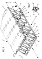
- Fig. 1
- einen Abschnitt des erfindungsgemäß ausgebildeten Bauteils in perspektivischer Darstellung, stark vergrößert,
- Fig. 2
- den Schnitt gemäß Linie II-II in Fig. 1,
- Fig. 3
- das Bauteil in Seitenansicht in Richtung A gesehen, weitestgehend schematisiert,
- Fig. 4
- das Bauteil in Seitenansicht in Richtung B gesehen, ebenfalls weitestgehend schematisiert,
- Fig. 5
- in Seitenansicht eine Verbindungszone zwischen zwei Velour-Gewebeabschnitten eines Bauteils,
- Fig. 6
- ein Bauteil in abgewandelter Ausbildung, und zwar in Seitenansicht in Richtung A gesehen, wiederum weitestgehend schematisiert,
- Fig. 7
- den Einsatz eines Zackenblattes in schematischer Darstellung,
- Fig. 8
- eine Variante des Gewebes gemäß Fig. 6, unterschiedliche Zwischensteg-Abstände darstellend,
- Fig. 9
- eine Weiterbildung dergestalt, daß zwischen die Zwischenstege gekreuzt verlaufende Zwischenstege eingeschaltet sind,
- Fig. 10
- eine Eckausbildung des Bauteils,
- Fig. 11
- das Bauteil mit auslaufender Randabflachung unter Einsatz der Gewebevariante Fig. 8 und
- Fig. 12
- eine solche unter Verwendung der Gewebevariante Fig. 9.
- Fig. 1
- a portion of the component designed according to the invention in a perspective view, greatly enlarged,
- Fig. 2
- the section along line II-II in Fig. 1,
- Fig. 3
- the component seen in side view in direction A, largely schematic,
- Fig. 4
- the component seen in side view in direction B, also largely schematized,
- Fig. 5
- in side view a connection zone between two velor fabric sections of a component,
- Fig. 6
- a component in a modified design, seen in side view in direction A, again largely schematic,
- Fig. 7
- the use of a serrated blade in a schematic representation,
- Fig. 8
- 6 shows a variant of the fabric according to FIG. 6, showing different spacing between the webs,
- Fig. 9
- a further development in such a way that intermediate webs which cross between the intermediate webs are switched on,
- Fig. 10
- a corner formation of the component,
- Fig. 11
- the component with tapering edge flattening using the fabric variant Fig. 8 and
- Fig. 12
- one using the fabric variant FIG. 9.
Das dargestellte Bauteil 1 wird auf einer Velourswebmaschine erzeugt. Das entsprechende Veloursgewebe bzw. Raschelplüschgewebe ist mehrlagig, beim Ausführungsbeispiel zweilagig. Eine erste, obere Lage trägt das Bezugszeichen 2; eine zweite, untere Lage ist dagegen mit 3 bezeichnet.The
Miteingewebte Stützfäden, welche Zwischenstege 4 bilden, halten die beiden Lagen 2,3 verbindend auf Abstand zueinander. Es liegt die ungespaltene Struktur einer Doppelsamt-Einbindung vor.Co-woven support threads, which form
Die Anzahl der Stützfäden ergibt sich aus der Schußdichte der Lage 2 und 3, ferner der Stützfadenzahl, gemessen über die Webbreite und schließlich aus der Rapportgröße der Bindung. Bei beispielsweise 2000 Fäden pro 1 m Webbreite, 12 Schuß/cm in der oberen Lage und der unteren Lage sowie 3/6 Schuß Bindung ergeben sich 800.000 Zwischenstege 4 zwischen den beiden Lagen 2,3.The number of support threads results from the weft density of the
Durch Verändern der Stegfadenzahl und Schußdichte sowie Bindung, können mehrfach höhere oder auch niedrigere Zwischenstege 4 eingewebt werden. Die erforderliche Festigkeit der oberen Lage 2 und der unteren Lage 3 und Biegefestigkeit werden durch entsprechenden Materialeinsatz von Kette und Schuß in den Decklagen erreicht. Natürlich ist die Steghöhe variierbar und kann, der gewünschten Höhe entsprechend individuell eingestellt werden.By changing the number of web threads and weft density as well as binding,
Verarbeitet werden technische Garne wie Aramidfaser, Kohlefaser, Keramikfaser oder insbesondere Glasfaser.Technical yarns such as aramid fiber, carbon fiber, ceramic fiber or in particular glass fiber are processed.
Zufolge der solchen Hochleistungsfasern innewohnenden Rückstellkraft und auch bedingt durch die Verbindungsstruktur haben die die Zwischenstege 4 bildenden Stützfäden das Bestreben, sich nach dem Weben aufzurichten bzw.in belastungsfreiem Zustand zurückzustellen. Das führt zu einer parallelen Beabstandung der Lagen 2 und 3. Der lichte Abstand x zwischen den beiden Lagen 2 und 3 entspricht einem Vielfachen einer Lagendicke.As a result of the restoring force inherent in such high-performance fibers and also due to the connection structure, the support threads forming the
Die den Pohlfäden einer Velour-Doppelsamtbindung vergleichbaren Zwischenstege 4 sind wie der ganze Bauteilkörper durch aushärtendes Harz versteift, so daß die Zwischenstege 4 zwischen der ersten Lage 2 und der zweiten Lage 3 starre Beabstandungselemente bilden. Das Zurückstellen der Zwischenstege 4 in ihre aus Fig. 1 ersichtliche Endstellung geschieht selbst nach dem völligen Zusammendrücken der Webstruktur. Entsprechend entstehen auch beim Webprozess zufolge der notwendigen Umlenkungen keinerlei Beschädigungen, welcher Tatbestand sich bei der Herstellung solcher Bauteile vorteilhaft nutzen läßt.The
Wie den Figuren entnehmbar, ist die mittlere Länge der Zwischenstege 4 größer als der lichte Abstand x zwischen den Lagen 2,3. Die sie bildenden freien Stützfädenabschnitte wechseln also nicht auf kürzestem Wege zwischen den beiden benachbarten Lagen 2,3. Es ergibt sich vielmehr, wie aus Fig. 1 ersichtlich, eine leichte Neigungslage, gesehen aus der Betrachtungsrichtung A in Fig. 1. Deutlicher geht dies noch aus der schematischen Darstellung beispielsweise gemäß Fig. 3 hervor. Bezüglich aller Zwischenstege 4 ist eine gleichgerichtete Schrägung angewandt, so daß von einem eingeregelten Schrägungsverlauf gesprochen werden kann.As can be seen from the figures, the average length of the
Der diesbezügliche Schrägungswinkel Alpha beträgt gemäß Fig. 3 ca. 65°, bezogen auf die horizontale Auflagebasis des Bauteils 1, also eine Waagerechte.The corresponding helix angle alpha is, according to FIG. 3, approximately 65 °, based on the horizontal support base of
Gemäß Variante Fig. 6 schließen alle Zwischenstege 4 mit der genannten Waagerechten einen Winkel Alpha von ca. 85° ein. Es liegt hier also eine sehr steile Schräglage vor.According to variant Fig. 6, all
Die Variante Fig. 8 verkörpert eine Lösung dahingehend, daß die Zwischenstege 4 mit abwechselnd großen und kleinen Abständen angeordnet sind. Der größere Abstand entspricht etwa dem doppelten kleinen Abstand der parallel verlaufenden Zwischenstege. In Fig. 8 sind diese Zwischenstege in einer Winkelstellung zur Waagerechten wie zu Fig. 6 ausgeführt.The variant Fig. 8 embodies a solution in that the
Gleiches gilt auch für die Variante Fig. 9 mit dem Unterschied jedoch, daß zwischen jeweils zwei Zwischenstegen 4 zu einander gekreuzt verlaufende Zwischenstege 8 vorgesehen sind. Letztere befinden sich in dem größeren Abstandsbereich zwischen zwei Zwischenstegen 4. Der Kreuzungswinkel Beta liegt bei 50° zur Waagerechten. Die die Zwischenstege 8 bildenden Polfäden des Gewebes wurzeln in einem Abstand zur benachbarten Zwischensteg-Reihe der etwa einem Fünftel der Länge eines Zwischensteges 8 entspricht.The same also applies to the variant in FIG. 9, with the difference, however, that
Aus der Betrachtungsrichtung B in Fig. 1 ergibt sich dagegen in allen Fällen eine vertikale Ausrichtung (vergleiche Fig. 4) zur genannten Basis.On the other hand, the viewing direction B in FIG. 1 results in a vertical orientation (compare FIG. 4) to the base mentioned in all cases.
Der Begriff "mittlere Länge" ist gewählt, weil die Zwischenstege 4 jeweils aus schwach gedrillten Einzelstegen 4′, 4˝ bestehen, die echte Länge als größer ausfällt. Der schwach wendelförmige Anstieg ergibt sich aus der perspektivischen Darstellung, Fig. 1. Ein Einzelsteg wechselt, in Richtung Pfeil B gesehen, von hinten nach vorne in Neigungsrichtung, und zwar bezogen auf den lagenseitigen Austrittsbereich.The term "medium length" is chosen because the
Der Zwischensteg 4 ist so zu einer Acht gedrillt (vergleichbar einem um seine Längsachse um 180 Grad verdrehten Ovalring), wobei die Einzelstege 4′, 4˝ in ihrem Überkreuzungsbereich 5 miteinander verbunden sind. Erreicht sind solche knotenpunktartigen Überkreuzungsbereiche 5 durch berührendes Aufeinanderliegen der die Acht bildenden Schleifenabschnitte der Zwischenstege 4.The
Im lagenseitigen Austrittsbereich und entsprechend natürlich auch im Eintrittsbereich weisen die Zwischenstege 4, 8 sokkelartige Übergangsbereiche 6 auf, etwa überirdischen Wurzelansätzen von Bäumen etc. vergleichbar. Das führt zu einem praktisch kegelstumpfartigen Übergang zwischen der Innenseite der Lagen und den Beabstandungselementen. Die Kebelstumpfbasis entspricht dem Mehrfachen des Querschnitts eines Einzelsteges 4′ bzw. 4˝. Die in Fig. 1 oberseitig erkennbaren Kreisfelder sollen den Lagen-Eintrittsbereich der Zwischenstege 4 symbolisieren. Es liegt eine W-Einbindung zugrunde.In the layer-side exit area and, of course, also in the entry area, the
Der als Acht gestaltete Zwischensteg 4 schafft nach Bindung im Überkreuzungsbereich 5 zwei tropfenförmige oder kettengliedartige Abschnitte, deren Höhlung mit a,b bezeichnet ist, und die je nach Nachbarschaftlage der Einzelstege 4′, 4˝, jedoch auch ganz oder teilweise mit Harz ausgefüllt sein können.The
So oder auch bei Freistand der Einzelstege 4′, 4′′ ergibt sich stets ein hochfester, säulen- bzw. strebenartiger, trotzdem eine gewisse Flexibilität auch in Achsrichtung aufweisender Distanzkörper.In this way or when the individual webs 4 ', 4' 'are always free, there is always a high-strength, columnar or strut-like, nevertheless a certain flexibility also in the axial direction having spacers.
Partielle Belastungen an den Breitflächen des Bauteiles 1 bringen auch die im weiteren Umfeld liegenden Zwischenstege in Beteiligung, da zufolge der leichten, überdies auch noch gleichgerichteten Neigungslage eine gegenläufige Verschiebebewegung (Pfeile z,z′ in Fig. 1) der Lagen 2 und 3 aufkommt. Neben dieser guten Lastverteilung wirkt sich auch noch die beschriebene Gestalt der Zwischenstege 4 kräfteverzehrend aus.Partial loads on the wide surfaces of
Eine gleichbleibende Parallelität der Lagen 2 und 3 erhält man durch Anschlagen des Schußfadens 9 der oberen und unteren Gewebelage mittels eines Zackenblatts 10 (vergl. Fig. 7). Die Rietstäbe des Zackenblatts 10 besitzen warenseitig Kerben 11, deren Grund den Mittenabstand y der Lagen 2 und 3, sprich Ober- und Unterware, definiert. Der Abstand kann beispielsweise bei 8 mm liegen. Das Zackenblatt erlaubt überdies eine höhenmäßig exakte Anschlagung der Schußfäden 9.A constant parallelism of the
Die Kettfäden sind durchweg mit 12 bezeichnet und bilden die Zwischenstege 4, 8.The warp threads are designated 12 throughout and form the
Die ungleichmäßige Verteilung der Zwischenstege führt zu relativ großen Zwischenräumen. Dadurch wird die Harzaufnahme geringer. Die Teile weisen ein leichteres Gewicht auf. Die kreuzförmige Sperrung der Räume erhöht überdies die Festigkeit.The uneven distribution of the intermediate webs leads to relatively large spaces. This reduces resin absorption. The parts are lighter in weight. The cross-shaped blocking of the rooms also increases the strength.
Die Anwendungsbeispiele gemäß Figuren 10 bis 12 zeigen anhand des Ausführungsbeispieles Fig. 10 eine Eckausbildung, bei der sich die obere Lage 2 in die Innenecke des winkelförmig gestalteten Bauteils einfaltet. Gesperrt werden kann diese Konstellation durch eine innenseitig aufgelegte Zusatzlage 13. Die Zusatzlage 13 nimmt einen im wesentlichen parallelen Rundungsverlauf zur Scheitelzone 14 des Profils.The application examples according to FIGS. 10 to 12 show, based on the exemplary embodiment in FIG. 10, a corner configuration in which the
In den Figuren 11 und 12 sind Bauteillaminate wiedergegeben. Diese sind randverbunden. Die Randzone 15 ist auf ein Minimum der Gesamtdicke reduziert. Das geschieht durch Bündelung der Lagen 2, 3 jedes Bauteils 1. Vorteilhaft ist noch die gegenläufige Schrägungsausrichtung der einzelnen Bauteile 1. Das führt zu einem inneren Versperren und einer sehr hohen Festigkeit des Gesamtbauteils.Component laminates are shown in FIGS. 11 and 12. These are bordered. The
Getränkt ist die erläuterte Gewebestruktur mit markerhältlichem Harz plus Härter. Die überschüssige Harzmenge wird abgequetscht oder ausgerollt, so daß die innere Struktur bis auf die benetzten, stegbildenden Stützfäden und die beiden getränkten Gewebelagen harzfrei ist. Die jeweils etwas ortsversetzten Eintrittsbereiche der Einzelstege 4′, 4′′ führen zu einer Gleitbewegung an den Schenkelabschnitten bis in die maximale Rückstellzone. Hierbei wird genügend Harz abstreifend mitgeschleppt, so daß die Überkreuzungsbereiche 5 gut harzgesättigt sind; es wird auf Fig. 2 verwiesen, aus der eine solche Harzanhäufungszone erkennbar ist. Die entsprechende Evakuierung an Harz geschieht in einem Umfang, daß die Rückstellkraft der Zwischenstege 4 freigegeben wird, bis diese, wie schon angedeutet, ihre Grund- oder Endstellung erreichen. Nach dem Trockenprozess ergeben sich ausgehärtete Bauteile von hoher Steifigkeit und Druckfestigkeit. Die gute Verformbarkeit des Velourgewebes bzw. Raschelplüschgewebe läßt auch die Herstellung leicht sphärisch gekrümmter Bauteile zu.The fabric structure explained is soaked with marker-containing resin plus hardener. The excess amount of resin is squeezed or rolled out, so that the inner structure is resin-free except for the wetted, web-forming support threads and the two impregnated fabric layers. The entry positions of the individual webs 4 ', 4'', which are somewhat displaced in each case, lead to a sliding movement on the leg sections up to the maximum reset zone. Sufficient resin is dragged along so that the
Durch lokales und unterschiedliches Zusammendrücken der getränkten Gewebe lassen sich ferner verschiedene Bauteilstärken aus einem Gewebe realisieren.Local and different compression of the impregnated tissue also enables different component thicknesses to be realized from one tissue.
Der verwirklichte sandwichartige Aufbau wirkt zufolge einer einzigen zusammenhängenden Struktur jeder Delaminierungstendenz, etwa im Sinne eines Ablösens einer Lage, entgegen.The realized sandwich-like structure counteracts any delamination tendency, for example in the sense of a layer peeling off, due to a single coherent structure.
Im Falle größerer, die Webbreite überschreitender Bauteile wird ein solches Bauteil 1 aus mehreren Gewebeabschnitten 1′, 1′′ zusammengesetzt. Hierzu wird der eine Velour-Gewebeabschnitt 1′ im Verbindungsbereich zum andern Velour-Gewebeabschnitt 1′′ gespalten. Diese Maßnahme geht aus der schematischen Darstellung in Fig. 5 hervor. Der Spalt ist dort mit 7 bezeichnet und wird durch einen Mittenschnitt entsprechend der gewünschten Überlappungstiefe erzeugt. Die korrespondierende Randzone des anschließenden Gewebeabschnitts 1′′ setzt man in die so geschaffene Öffnung ein. Unter Beibehaltung einer gleichbleibenden Gesamtdicke des Bauteiles 1 werden die verbindungsbereichsnahen Randlagen in Richtung des Abstandsraumes zusammengedrückt. Es folgt dann das beschriebene Tränken mittels Harz sowie Ausquetschen. Das Gewebe stellt sich in der erläuterten Weise zurück. Durch rückenseitige Abstützung im Verbindungsbereich V kann die entsprechende Rückstellung begrenzt werden, so daß eine durchgehend gleiche Dicke des Bauteiles 1 vorliegt. Die stärker abgeplattete Randzone verschwindet im sowieso vorhandenen Abstandsraum. Die durch Spaltschnitt freistehenden bürstenartigen Stegstoppeln vergraben sich verankernd in der Außenseite des überlappten Randes des Gewebeabschnitts 1′′. Letzteres führt zu einem innigen haltbaren Verbund.In the case of larger components that exceed the weaving width, such a
Claims (14)
- Pile fabric-based component, with at least one first (2) and second (3) layer and intermediate webs connecting these layers (2, 3), wherein the pile fabric consists of a commercial yarn such as aramide fibre, carbon fibre, ceramic fibre or in particular glass fibre, and wherein the pile fabric is resinified to the point of hardening, wherein the intermediate webs (4) form rigid spacer elements of the first layer (2) and second layer (3) and consist of helically twisted single webs (4', 4'').
- Component according to claim 1, characterised in that the mean length of the intermediate webs (4) is greater than the distance (x) between the layers (2, 3).
- Component according to one or more of the preceding claims, characterised in that the intermediate webs (4) are adjusted to extend at an angle.
- Component according to one or more of the preceding claims, characterised in that the intermediate webs (4) form an angle (alpha) of about 65° with a horizontal.
- Component according to one or more of the preceding claims, characterised in that the intermediate webs (4) form an angle (alpha) of about 95° with a horizontal.
- Component according to one or more of the preceding claims, characterised in that an intermediate web (4) consists of two slightly twisted single webs (4', 4'').
- Component according to one or more of the preceding claims, characterised in that the intermediate web (4) consists of single webs (4', 4'') twisted in a figure of eight.
- Component according to one or more of the preceding claims, characterised in that the single webs (4', 4'') are connected to each other in their region of crossing over (5).
- Component according to one or more of the preceding claims, characterised in that the intermediate webs (4) comprise pedestal-like junction zones (6) in the exit region of the layers (2, 3).
- Component according to one or more of the preceding claims, characterised in that the intermediate webs (4) are arranged alternately at longer and shorter intervals.
- Component according to one or more of the preceding claims, characterised in that intermediate webs (8) crossed with each other are interposed.
- Method for the manufacture of a component, in particular according to any of claims 1 to 11, by resinification and subsequent hardening of a fabric, wherein after resinification of the fabric, partial removal of resin is performed by squeezing, characterised in that where a pile fabric which forms intermediate webs as rigid spacer elements between the first and second layers is used, resin is removed to such an extent that the return force of intermediate webs (4 or 8) is released.
- Method according to claim 12, characterised in that during the weaving process, looping of the weft threads (9) by hand is carried out in a manner known in the art by means of a toothed sheet (10).
- Method according to claim 12, wherein the component is composed of several fabric sections, characterised in that one pile fabric section (1') is split in the junction zone (V) and the other pile fabric section (1'') is laid in the opening formed in this way.
Priority Applications (1)
| Application Number | Priority Date | Filing Date | Title |
|---|---|---|---|
| AT88110601T ATE72471T1 (en) | 1987-07-17 | 1988-07-02 | COMPONENT BASED ON VELOR FABRIC AND PROCESS FOR ITS MANUFACTURE. |
Applications Claiming Priority (2)
| Application Number | Priority Date | Filing Date | Title |
|---|---|---|---|
| DE19873723681 DE3723681A1 (en) | 1987-07-17 | 1987-07-17 | VELOURS FABRIC-BASED COMPONENT AND METHOD FOR THE PRODUCTION THEREOF |
| DE3723681 | 1987-07-17 |
Publications (3)
| Publication Number | Publication Date |
|---|---|
| EP0299308A2 EP0299308A2 (en) | 1989-01-18 |
| EP0299308A3 EP0299308A3 (en) | 1989-05-31 |
| EP0299308B1 true EP0299308B1 (en) | 1992-02-05 |
Family
ID=6331791
Family Applications (1)
| Application Number | Title | Priority Date | Filing Date |
|---|---|---|---|
| EP88110601A Expired - Lifetime EP0299308B1 (en) | 1987-07-17 | 1988-07-02 | Building element made from a velvet texture and method for its manufacture |
Country Status (12)
| Country | Link |
|---|---|
| US (2) | US4840828A (en) |
| EP (1) | EP0299308B1 (en) |
| JP (1) | JP2590214B2 (en) |
| AT (1) | ATE72471T1 (en) |
| BR (1) | BR8803585A (en) |
| CA (1) | CA1323288C (en) |
| DD (1) | DD285386A5 (en) |
| DE (2) | DE3723681A1 (en) |
| ES (1) | ES2030116T3 (en) |
| GR (1) | GR3003861T3 (en) |
| HK (1) | HK138593A (en) |
| IL (1) | IL87120A (en) |
Families Citing this family (33)
| Publication number | Priority date | Publication date | Assignee | Title |
|---|---|---|---|---|
| NL187076C (en) * | 1986-12-08 | 1991-05-16 | Parabeam Bv | METHOD FOR MANUFACTURING A DOUBLE FABRIC AND A DOUBLE FABRIC FOR DOUBLE FABRIC FOR CARRYING OUT THAT METHOD |
| DE3903216A1 (en) * | 1989-02-03 | 1990-08-09 | Parabeam Bv | Airbag |
| FR2645881B1 (en) * | 1989-04-14 | 1992-06-12 | Hexcel Genin Sa | THERMO-PLASTIC FABRIC |
| DE69101397T2 (en) * | 1990-05-31 | 1994-06-23 | United Technologies Corp | Composite article made from fiber-reinforced glass binder and glass-ceramic binder. |
| DE4100738A1 (en) * | 1991-01-12 | 1992-07-16 | Vorwerk Co Interholding | COMPONENT BASED ON A DISTANCE FABRIC |
| US5534318A (en) * | 1991-03-18 | 1996-07-09 | Parabeam Industrie-En Handelsonderneming B.V. | Hollow fiber-reinforced plastic body |
| DE9104141U1 (en) * | 1991-04-05 | 1992-08-13 | Vorwerk & Co Interholding Gmbh, 5600 Wuppertal, De | |
| IT1250827B (en) * | 1991-07-30 | 1995-04-21 | Metalleido Srl | MODULAR LIVING MODULE. |
| US5699796A (en) * | 1993-01-29 | 1997-12-23 | Cardima, Inc. | High resolution intravascular signal detection |
| DE4202589C1 (en) * | 1992-01-30 | 1993-04-22 | Deutsche Aerospace Ag, 8000 Muenchen, De | Prodn. of integral sandwich structure from preformed textile - comprises impregnating core yarns with hardenable plastic and placing between rigid baseplate and covering plate |
| DE4215662A1 (en) * | 1992-05-13 | 1993-11-18 | Akzo Nv | Textile anti-vandalism fabric |
| DE4228958A1 (en) * | 1992-08-31 | 1994-03-03 | Vorwerk Co Interholding | Spacer fabric |
| DE4300480A1 (en) * | 1993-01-11 | 1994-07-14 | Kunert Heinz | Safety glass element with thermal insulation properties |
| DE4300481A1 (en) * | 1993-01-11 | 1994-07-14 | Kunert Heinz | Frameless double glazing and process for its production |
| DE4327022C2 (en) * | 1993-08-12 | 1995-05-24 | Daimler Benz Ag | Element for absorbing impact energy, especially for vehicles |
| US6037035A (en) * | 1994-02-23 | 2000-03-14 | Vorwerk & Co. Interholding Gmbh | Spacer fabric |
| DE19502238A1 (en) * | 1995-01-25 | 1996-08-01 | Kunert Heinz | Heat insulated floor, ceiling or wall construction |
| AU4713896A (en) * | 1995-01-25 | 1996-08-14 | Heinz Kunert | Floor, ceiling or wall structure with highly effective thermal insulation |
| DE29504458U1 (en) * | 1995-03-16 | 1995-05-11 | Friedrich Geb | mat |
| US7051489B1 (en) * | 1999-08-12 | 2006-05-30 | Hunter Douglas Inc. | Ceiling system with replacement panels |
| KR20010081471A (en) * | 2000-02-15 | 2001-08-29 | 조문수 | Sandwich panel |
| US7377084B2 (en) * | 2000-04-24 | 2008-05-27 | Hunter Douglas Inc. | Compressible structural panel |
| US7048985B2 (en) * | 2001-07-23 | 2006-05-23 | Vrac, Llc | Three-dimensional spacer fabric resin infusion media and reinforcing composite lamina |
| US7060156B2 (en) * | 2001-07-23 | 2006-06-13 | Vrac, Llc | Three-dimensional spacer fabric resin interlaminar infusion media process and vacuum-induced reinforcing composite laminate structures |
| US6688338B2 (en) * | 2001-12-26 | 2004-02-10 | Paul Meli | Secondary containment system for pipelines |
| US7303641B2 (en) * | 2002-12-03 | 2007-12-04 | Hunter Douglas Inc. | Method for fabricating cellular structural panels |
| US20070022672A1 (en) * | 2005-07-11 | 2007-02-01 | Bachynski Michael R | Hurricane protection harness |
| DE202005010964U1 (en) | 2005-07-12 | 2006-11-23 | Jacob Composite Gmbh | Hybrid fastener |
| JP5318432B2 (en) * | 2008-02-12 | 2013-10-16 | 東レ・デュポン株式会社 | Defense pile fabric |
| DE102013101219B3 (en) | 2013-02-07 | 2014-06-12 | Technische Universität Dresden | Tissue structure with cellular construction |
| EP2778267B1 (en) * | 2013-03-11 | 2019-08-28 | Parabeam B.V. | Padding material for use as the cushioning, insulating or padding cover of objects or components |
| DE102013217990A1 (en) | 2013-09-09 | 2015-03-12 | hollomet GmbH | damping body |
| CN110863482B (en) * | 2019-12-06 | 2022-07-05 | 湖南易兴建筑有限公司 | Construction method of fiber ceramic building |
Family Cites Families (7)
| Publication number | Priority date | Publication date | Assignee | Title |
|---|---|---|---|---|
| US3138506A (en) * | 1959-12-08 | 1964-06-23 | Goodyear Aerospace Corp | Method of making an article of stiffened fibrous material |
| US3090406A (en) * | 1961-02-23 | 1963-05-21 | Raymond Dev Ind Inc | Woven panel and method of making same |
| FR1393269A (en) * | 1963-09-24 | 1965-03-26 | Lister & Company Ltd | Improvements to textile materials |
| US3481427A (en) * | 1968-11-29 | 1969-12-02 | Mc Donnell Douglas Corp | Acoustical panel structure |
| JPS61229543A (en) * | 1985-04-05 | 1986-10-13 | 旭化成株式会社 | Fiber reinforced thick elastic sheet |
| DE3540455C2 (en) * | 1985-11-14 | 1996-04-04 | Deutsche Heraklith | Inorganic multilayer lightweight board |
| US4873133A (en) * | 1986-09-11 | 1989-10-10 | General Electric Company | Fiber reinforced stampable thermoplastic sheet |
-
1987
- 1987-07-17 DE DE19873723681 patent/DE3723681A1/en not_active Withdrawn
-
1988
- 1988-07-02 DE DE8888110601T patent/DE3868297D1/en not_active Expired - Lifetime
- 1988-07-02 EP EP88110601A patent/EP0299308B1/en not_active Expired - Lifetime
- 1988-07-02 ES ES198888110601T patent/ES2030116T3/en not_active Expired - Lifetime
- 1988-07-02 AT AT88110601T patent/ATE72471T1/en not_active IP Right Cessation
- 1988-07-11 DD DD88317815A patent/DD285386A5/en not_active IP Right Cessation
- 1988-07-15 CA CA000572211A patent/CA1323288C/en not_active Expired - Lifetime
- 1988-07-15 US US07/219,398 patent/US4840828A/en not_active Ceased
- 1988-07-15 JP JP63175300A patent/JP2590214B2/en not_active Expired - Lifetime
- 1988-07-15 IL IL87120A patent/IL87120A/en not_active IP Right Cessation
- 1988-07-15 BR BR8803585A patent/BR8803585A/en unknown
-
1989
- 1989-10-11 US US07/419,756 patent/USRE33923E/en not_active Expired - Lifetime
-
1992
- 1992-02-21 GR GR920400276T patent/GR3003861T3/el unknown
-
1993
- 1993-12-16 HK HK1385/93A patent/HK138593A/en not_active IP Right Cessation
Also Published As
| Publication number | Publication date |
|---|---|
| US4840828A (en) | 1989-06-20 |
| ES2030116T3 (en) | 1992-10-16 |
| JP2590214B2 (en) | 1997-03-12 |
| IL87120A (en) | 1992-05-25 |
| EP0299308A3 (en) | 1989-05-31 |
| ATE72471T1 (en) | 1992-02-15 |
| CA1323288C (en) | 1993-10-19 |
| IL87120A0 (en) | 1988-12-30 |
| HK138593A (en) | 1993-12-24 |
| EP0299308A2 (en) | 1989-01-18 |
| BR8803585A (en) | 1989-02-08 |
| USRE33923E (en) | 1992-05-12 |
| DD285386A5 (en) | 1990-12-12 |
| JPH0197273A (en) | 1989-04-14 |
| GR3003861T3 (en) | 1993-03-16 |
| DE3868297D1 (en) | 1992-03-19 |
| DE3723681A1 (en) | 1989-01-26 |
Similar Documents
| Publication | Publication Date | Title |
|---|---|---|
| EP0299308B1 (en) | Building element made from a velvet texture and method for its manufacture | |
| EP0339227B1 (en) | Construction element on a knitwear basis, and method for its manufacture | |
| EP0299309B1 (en) | Construction element based on a multilayered fabric, and process for its manufacture | |
| DE2757965C3 (en) | Thrust transmission element and method for its production | |
| EP0746645B1 (en) | Spaced fabric | |
| DE2164700A1 (en) | Cloth for making paper and cellulose | |
| DE2927414A1 (en) | Resinous laminates reinforcing fabric - with weft knit stitches anchoring lengthwise parallel warp inserts each comprising parallel monofil groups | |
| EP0873440B1 (en) | Multilayer knitted structure and method of producing the same | |
| DE3813740A1 (en) | FABRIC FOR PRODUCING A COMPONENT | |
| WO2017190812A1 (en) | Plastic mesh having double chains, and device for producing a plastic mesh | |
| DE2052431A1 (en) | Glass fiber reinforced, multi-layer plastic laminate, in particular glass fiber fabric for such a plastic laminate | |
| DE2209928A1 (en) | THREE-DIMENSIONAL FABRIC AND METHOD OF MANUFACTURING IT | |
| DE102007038931A1 (en) | Thread layer sewing material i.e. laminar textile for producing of spatial armoring structures for e.g. concrete part, has warp threads whose lengths between two weft threads are variable in warping and fill directions in lattice structure | |
| DE2341333C2 (en) | bearings | |
| DE1560896B1 (en) | Method of manufacturing rigid plastic laminates | |
| DE4411931A1 (en) | Spacer fabric | |
| EP1053094B1 (en) | Flat material strip and method for producing fibre composite workpieces with such flat material strips | |
| DE102013108372B4 (en) | Fabrics and process for their manufacture | |
| DE2028582B2 (en) | Tissue that can be stressed in tension, in particular for belts rotating in machines, as well as a method for producing such a fabric | |
| DE1560896C (en) | Process for the production of rigid plastic laminates | |
| DE1248005B (en) | Resin-impregnated, rigid woven element | |
| DE1704670C3 (en) | Reinforcement insert for plastic articles and process for their manufacture | |
| DE2119862A1 (en) | Epoxy resin ski - with knitted glass fibre reinforcing layers and ptfe gliding surface | |
| DE2119493C3 (en) | Method and device for producing pile fabrics | |
| DE2715574C2 (en) | Process for producing a pile fabric and fabric weave for a blanket to be produced by this process |
Legal Events
| Date | Code | Title | Description |
|---|---|---|---|
| PUAI | Public reference made under article 153(3) epc to a published international application that has entered the european phase |
Free format text: ORIGINAL CODE: 0009012 |
|
| AK | Designated contracting states |
Kind code of ref document: A2 Designated state(s): AT BE CH DE ES FR GB GR IT LI LU NL SE |
|
| PUAL | Search report despatched |
Free format text: ORIGINAL CODE: 0009013 |
|
| AK | Designated contracting states |
Kind code of ref document: A3 Designated state(s): AT BE CH DE ES FR GB GR IT LI LU NL SE |
|
| 17P | Request for examination filed |
Effective date: 19890522 |
|
| 17Q | First examination report despatched |
Effective date: 19900807 |
|
| GRAA | (expected) grant |
Free format text: ORIGINAL CODE: 0009210 |
|
| AK | Designated contracting states |
Kind code of ref document: B1 Designated state(s): AT BE CH DE ES FR GB GR IT LI LU NL SE |
|
| REF | Corresponds to: |
Ref document number: 72471 Country of ref document: AT Date of ref document: 19920215 Kind code of ref document: T |
|
| ET | Fr: translation filed | ||
| REF | Corresponds to: |
Ref document number: 3868297 Country of ref document: DE Date of ref document: 19920319 |
|
| ITF | It: translation for a ep patent filed |
Owner name: STUDIO JAUMANN |
|
| GBT | Gb: translation of ep patent filed (gb section 77(6)(a)/1977) | ||
| REG | Reference to a national code |
Ref country code: ES Ref legal event code: FG2A Ref document number: 2030116 Country of ref document: ES Kind code of ref document: T3 |
|
| REG | Reference to a national code |
Ref country code: GR Ref legal event code: FG4A Free format text: 3003861 |
|
| PLBE | No opposition filed within time limit |
Free format text: ORIGINAL CODE: 0009261 |
|
| STAA | Information on the status of an ep patent application or granted ep patent |
Free format text: STATUS: NO OPPOSITION FILED WITHIN TIME LIMIT |
|
| 26N | No opposition filed | ||
| NLS | Nl: assignments of ep-patents |
Owner name: VORWERK & CO. INTERHOLDING GMBH TE WUPPERTAL EN ME |
|
| EPTA | Lu: last paid annual fee | ||
| EAL | Se: european patent in force in sweden |
Ref document number: 88110601.7 |
|
| REG | Reference to a national code |
Ref country code: GB Ref legal event code: IF02 |
|
| REG | Reference to a national code |
Ref country code: CH Ref legal event code: PUE Owner name: ZCL COMPOSITES INC. Free format text: VORWERK & CO. INTERHOLDING GMBH#MUEHLENWEG 17-37 POSTFACH 20 16 11#D-42216 WUPPERTAL (DE) -TRANSFER TO- ZCL COMPOSITES INC.#6907-36 STREET#EDMONTON, ALBERTA T6B 2Z6 (CA) |
|
| REG | Reference to a national code |
Ref country code: FR Ref legal event code: TP |
|
| REG | Reference to a national code |
Ref country code: GB Ref legal event code: 732E |
|
| PGFP | Annual fee paid to national office [announced via postgrant information from national office to epo] |
Ref country code: LU Payment date: 20070618 Year of fee payment: 20 |
|
| PGFP | Annual fee paid to national office [announced via postgrant information from national office to epo] |
Ref country code: ES Payment date: 20070621 Year of fee payment: 20 |
|
| PGFP | Annual fee paid to national office [announced via postgrant information from national office to epo] |
Ref country code: DE Payment date: 20070704 Year of fee payment: 20 |
|
| PGFP | Annual fee paid to national office [announced via postgrant information from national office to epo] |
Ref country code: GB Payment date: 20070627 Year of fee payment: 20 Ref country code: AT Payment date: 20070614 Year of fee payment: 20 |
|
| PGFP | Annual fee paid to national office [announced via postgrant information from national office to epo] |
Ref country code: IT Payment date: 20070726 Year of fee payment: 20 Ref country code: BE Payment date: 20070702 Year of fee payment: 20 Ref country code: SE Payment date: 20070705 Year of fee payment: 20 Ref country code: NL Payment date: 20070704 Year of fee payment: 20 |
|
| PGFP | Annual fee paid to national office [announced via postgrant information from national office to epo] |
Ref country code: CH Payment date: 20071026 Year of fee payment: 20 |
|
| PGFP | Annual fee paid to national office [announced via postgrant information from national office to epo] |
Ref country code: GR Payment date: 20070220 Year of fee payment: 20 |
|
| PGFP | Annual fee paid to national office [announced via postgrant information from national office to epo] |
Ref country code: FR Payment date: 20070612 Year of fee payment: 20 |
|
| REG | Reference to a national code |
Ref country code: GB Ref legal event code: PE20 Expiry date: 20080701 |
|
| BE20 | Be: patent expired |
Owner name: *ZCL COMPOSITES INC. Effective date: 20080702 |
|
| REG | Reference to a national code |
Ref country code: CH Ref legal event code: PL |
|
| NLV7 | Nl: ceased due to reaching the maximum lifetime of a patent |
Effective date: 20080702 |
|
| EUG | Se: european patent has lapsed | ||
| REG | Reference to a national code |
Ref country code: ES Ref legal event code: FD2A Effective date: 20080703 |
|
| PG25 | Lapsed in a contracting state [announced via postgrant information from national office to epo] |
Ref country code: GB Free format text: LAPSE BECAUSE OF EXPIRATION OF PROTECTION Effective date: 20080701 Ref country code: NL Free format text: LAPSE BECAUSE OF EXPIRATION OF PROTECTION Effective date: 20080702 |
|
| PG25 | Lapsed in a contracting state [announced via postgrant information from national office to epo] |
Ref country code: ES Free format text: LAPSE BECAUSE OF EXPIRATION OF PROTECTION Effective date: 20080703 |