EP0298551B1 - Device for adjusting the orientation of headlights of motor-vehicles - Google Patents
Device for adjusting the orientation of headlights of motor-vehicles Download PDFInfo
- Publication number
- EP0298551B1 EP0298551B1 EP88201350A EP88201350A EP0298551B1 EP 0298551 B1 EP0298551 B1 EP 0298551B1 EP 88201350 A EP88201350 A EP 88201350A EP 88201350 A EP88201350 A EP 88201350A EP 0298551 B1 EP0298551 B1 EP 0298551B1
- Authority
- EP
- European Patent Office
- Prior art keywords
- bush
- screw
- integral
- container
- fastened
- Prior art date
- Legal status (The legal status is an assumption and is not a legal conclusion. Google has not performed a legal analysis and makes no representation as to the accuracy of the status listed.)
- Expired - Lifetime
Links
Images


Classifications
-
- B—PERFORMING OPERATIONS; TRANSPORTING
- B60—VEHICLES IN GENERAL
- B60Q—ARRANGEMENT OF SIGNALLING OR LIGHTING DEVICES, THE MOUNTING OR SUPPORTING THEREOF OR CIRCUITS THEREFOR, FOR VEHICLES IN GENERAL
- B60Q1/00—Arrangement of optical signalling or lighting devices, the mounting or supporting thereof or circuits therefor
- B60Q1/02—Arrangement of optical signalling or lighting devices, the mounting or supporting thereof or circuits therefor the devices being primarily intended to illuminate the way ahead or to illuminate other areas of way or environments
- B60Q1/04—Arrangement of optical signalling or lighting devices, the mounting or supporting thereof or circuits therefor the devices being primarily intended to illuminate the way ahead or to illuminate other areas of way or environments the devices being headlights
- B60Q1/06—Arrangement of optical signalling or lighting devices, the mounting or supporting thereof or circuits therefor the devices being primarily intended to illuminate the way ahead or to illuminate other areas of way or environments the devices being headlights adjustable, e.g. remotely-controlled from inside vehicle
- B60Q1/068—Arrangement of optical signalling or lighting devices, the mounting or supporting thereof or circuits therefor the devices being primarily intended to illuminate the way ahead or to illuminate other areas of way or environments the devices being headlights adjustable, e.g. remotely-controlled from inside vehicle by mechanical means
- B60Q1/0683—Adjustable by rotation of a screw
Definitions
- the traffic-governing regulations prescribe that the light beams emitted by the headlights of the motor-vehicles are bounded in height and width within determined dimensions, in order to correctly lighten the road, as well as in order to prevent other drivers'eyes from being dazzled when vehicles cross.
- misorientations can occur in the angle of the light beams, e.g., due to impacts and vibrations transmitted by the bodywork, or due to the load conditions, which may vary within a minimum and a maximum.
- FR-A-2 319 512 shows a device according to the preamble of claim 1.
- the general purpose of the present invention is to provide a device of the above said type, which can be driven in an easy and comfortable way, which is safe and reliable in function, and which has a particularly compact, simple and reliable structure.
- said first and second screw spindles can be turned in and turned out inside their respective bushes by means of their respective drive bevel gears, and, consequently, through their pivots, they gradually shift the headlight in the longitudinal directions, causing it to tilt relatively to the transversal axis and the vertical axis formed by the two pivots which remain stationary.
- the above-said first screw spindle can be turned in and turned out integrally with the bush, relatively to the further bush, by making said box revolve and shifting the above-said finger from a slot into another slot, in such a way that the headlight is longitudinally shifted by large steps, in order to tilt relatively to the transversal axis formed by the two pivots which remain stationary.
- the means are advantageously combined, which make it possible the orientation of the headlights to be adjusted, both when fine adjustements, and when larger shifts are necessary, in particular in case of changes in motor-vehicle load.
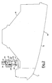
- the headlight of a motor-vehicle is generally indicated by the reference number 10, and by the reference number 11 the turn signal incorporated with it is indicated.
- the headlight is closed in its front portion by a transparent wall 12, which performs the function of refracting the light beam emitted by a lamp not shown in the figures.
- the transparent wall 12 is fastened to a container, indicated by the reference number 13, schematically depicted, and visible in figures 2, 3 and 4.
- the container is fastened in its turn to the vehicle bodywork by means of connection means, not shown in the figures.
- a reflector is indicated, e.g., of half-ellissoidal shape, visible in Figures 3 and 4, which supports a lamp, not shown in the Figures, and which is linked to the container 13 by means of three pivots, generally indicated by the reference numerals 15, 16, 17, having substantially longitudinal axes.
- the axes of the pivots 15, 16 and 17 are placed at the vertices of a substantially right-angled triangle, with a substantially vertical cathetus, containing the axes of the pivots 15 and 17, and with a substantially transversal cathetus, containing the axes of the pivots 16 and 17.
- the pivot 17 is formed by an annular protrusion 18, of semicircular cross-section, provided inside a bush of plastic material, 19, fastened to the reflector 14.
- the protrusion 18 gets engaged inside an annular groove, 20, also of a semicircular shape, provided in the cone-frustum head, 21, of a spindle 22 screw-threaded in 23 and screwed in an also threaded bush 24 integral with the wall of the container 13.
- the screw spindle 22 is stationary inside the bush 24.
- the pivot 15 is formed in its turn by an annular protrusion 26, of semicircular cross-section, provided inside a bush of plastic material, 27, fastened to the reflector 14.
- the protrusion 26 gets engaged inside an annular groove 28, also of a semicircular shape, provided in the cone-frustum head, 29, integral with the bottom wall 30 of a bush of plastic material, 31, having the shape of a cup, slidingly mounted inside a hole provided through the wall of the container 13.
- a partially spherical hollow 32 is formed, inside which the spherical head 33 is housed of a stud 34, which is integral with an end of a screw spindle 35, provided with a fine-pitch external screw-thread 36.
- the screw spindle 35 has a square-cross-section head 37, which engages with a hole 38 of square-cross-section, provided in a sleeve of plastic material, indicated by the reference numeral 39.
- the sleeve 39 is integral with a ring bevel gear indicated by the reference numeral 40, which inmeshes with a bevel gear indicated by the reference numeral 41, provided with a disc 42, equipped with notches 43, also visible in Figure 2, which can be engaged by a drive tool.
- Both bevel gears 40 and 41 are supported inside a box of a plastic material, indicated by the reference numeral 44.
- a bush indicated by the reference numeral 45 is integral, which is provided with an internal screw-thread which inmeshes with the screw-thread 36 of the screw spindle 35; the bush 45 is also equipped with an external, large-pitch screw-thread 46, which inmeshes with the internal screw-thread of a bush 47 fastened to the wall of the container 13.
- the slots 49 are longitudinal, and are spaced-apart by rather large pitches.
- the pivot 16, shown in Figure 4 is also formed by an annular protrusion 50, of semicircular cross-section, provided inside a bush of plastic material 51, fastened to the reflector 14.
- the protrusion 50 gets engaged inside an annular groove 52, also having a semicircular cross-section, provided in the cone-frustum head, 53, of a spindle 54 provided with an external fine-pitch screw-thread 55 which inmeshes with the screw-thread of a bush 56 integral with the wall of the container 13.
- the screw spindle 54 is also provided with a square head 57, which gets engaged inside a hole 58 of square cross-section, provided in a sleeve of a plastic material, 59.
- the sleeve 59 is integral with a ring bevel gear indicated by the reference numeral 60, which inmeshes with a bevel gear indicated by the reference numeral 61, provided with a disc 62, equipped with notches 63, which can be engaged by a drive tool.
- Both bevel gears 60 and 61 are supported inside a box of plastic material, indicated by the reference numeral 64, integral with the wall of the container 13 and between its cover 65 and the bevel gear 60 washers 66 of a self-lubricating material are interposed.
- the adjustment of the orientation of the headlight 10 relatively to the vertical axis containing the axes of the pivots 15 and 17, and concident with the axis III-III, is carried out by longitudinally shifting the pivot 16, i.e., turning in and out the spindle 54 inside the sleeve 56.
- the bevel gear 61 is caused to rotate by means of a drive tool, such as, e.g., a star screwdriver, and through the ring bevel gear 60, it causes the sleeve 59 to rotate; this latter, in its turn, drives the spindle 54 to rotate, through the square head 57.
- a drive tool such as, e.g., a star screwdriver
- the adjustment in the orientation of headlight 10, still relatively to the transversal plane containing the axes of the pivots 16 and 17, is carried out with large shifts e.g., in case of changes in vehicle load, between a minimum and a maximum, by rotating the box 44 and shifting the finger 48 from a slot 49 into another slot, so that the bush 45 turns in or out relatively to the bush 47.
Landscapes
- Engineering & Computer Science (AREA)
- Mechanical Engineering (AREA)
- Lighting Device Outwards From Vehicle And Optical Signal (AREA)
- Non-Portable Lighting Devices Or Systems Thereof (AREA)
Description
- The traffic-governing regulations prescribe that the light beams emitted by the headlights of the motor-vehicles are bounded in height and width within determined dimensions, in order to correctly lighten the road, as well as in order to prevent other drivers'eyes from being dazzled when vehicles cross.
- In the use of cars, misorientations can occur in the angle of the light beams, e.g., due to impacts and vibrations transmitted by the bodywork, or due to the load conditions, which may vary within a minimum and a maximum.
- Inasmuch as the changes in light beam angle have a negative influence on the lighting depth and on the dazzling conditions, the headlights are generally equipped with devices which make it possible their vertical and horizontal orientation to be adjusted, in order to restore the optimum orientation conditions. FR-A-2 319 512 shows a device according to the preamble of claim 1.
- The general purpose of the present invention is to provide a device of the above said type, which can be driven in an easy and comfortable way, which is safe and reliable in function, and which has a particularly compact, simple and reliable structure.
- The above purpose is achieved by means of a device according to claim 1.
- In that way, said first and second screw spindles can be turned in and turned out inside their respective bushes by means of their respective drive bevel gears, and, consequently, through their pivots, they gradually shift the headlight in the longitudinal directions, causing it to tilt relatively to the transversal axis and the vertical axis formed by the two pivots which remain stationary.
- Furthermore, the above-said first screw spindle can be turned in and turned out integrally with the bush, relatively to the further bush, by making said box revolve and shifting the above-said finger from a slot into another slot, in such a way that the headlight is longitudinally shifted by large steps, in order to tilt relatively to the transversal axis formed by the two pivots which remain stationary.
- Therefore, in a device the means are advantageously combined, which make it possible the orientation of the headlights to be adjusted, both when fine adjustements, and when larger shifts are necessary, in particular in case of changes in motor-vehicle load.
- Characteristics and advantages of the finding are now explained by referring to the thereto attached figures from 1 to 4, wherein for non-limitative exemplifying purposes, a preferred form of embodiment of the same invention is depicted.
- Figure 1 shows a front view of a headlight equipped with a device for adjusting the orientation thereof, having a structure according to the presente invention;
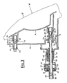
- Figure 2 shows a top view of the headlight of Figure 1;
- Figure 3 shows a partial sectional view according to the plane identified by path III-III of Figure 1, shown on an enlarged scale relatively to Figure 1;
- Figure 4 shows a partial sectional view according to the plane identified by path IV-IV of Figure 1, also shown on an enlarged scale relatively to Figure 1.
- In Figure 1, the headlight of a motor-vehicle is generally indicated by the
reference number 10, and by thereference number 11 the turn signal incorporated with it is indicated. - The headlight is closed in its front portion by a
transparent wall 12, which performs the function of refracting the light beam emitted by a lamp not shown in the figures. - The
transparent wall 12 is fastened to a container, indicated by thereference number 13, schematically depicted, and visible in figures 2, 3 and 4. - The container is fastened in its turn to the vehicle bodywork by means of connection means, not shown in the figures.
- By the reference numeral 14 a reflector is indicated, e.g., of half-ellissoidal shape, visible in Figures 3 and 4, which supports a lamp, not shown in the Figures, and which is linked to the
container 13 by means of three pivots, generally indicated by thereference numerals - The axes of the
pivots pivots pivots - The above-said triangle can be imagined by looking at Figure 1, wherein the vertical cathetus would coincide with the axis III-III and the transversal cathetus would join the axes III-III and IV-IV in their upper part.
- As shown in Figure 3, the
pivot 17 is formed by an annular protrusion 18, of semicircular cross-section, provided inside a bush of plastic material, 19, fastened to thereflector 14. - The protrusion 18 gets engaged inside an annular groove, 20, also of a semicircular shape, provided in the cone-frustum head, 21, of a spindle 22 screw-threaded in 23 and screwed in an also threaded
bush 24 integral with the wall of thecontainer 13. The screw spindle 22 is stationary inside thebush 24. - The
pivot 15 is formed in its turn by anannular protrusion 26, of semicircular cross-section, provided inside a bush of plastic material, 27, fastened to thereflector 14. - The
protrusion 26 gets engaged inside anannular groove 28, also of a semicircular shape, provided in the cone-frustum head, 29, integral with thebottom wall 30 of a bush of plastic material, 31, having the shape of a cup, slidingly mounted inside a hole provided through the wall of thecontainer 13. - In the
wall bottom 30 of the bush 31 a partiallyspherical hollow 32 is formed, inside which thespherical head 33 is housed of astud 34, which is integral with an end of ascrew spindle 35, provided with a fine-pitch external screw-thread 36. At its other end, thescrew spindle 35 has a square-cross-section head 37, which engages with ahole 38 of square-cross-section, provided in a sleeve of plastic material, indicated by thereference numeral 39. - The
sleeve 39 is integral with a ring bevel gear indicated by thereference numeral 40, which inmeshes with a bevel gear indicated by thereference numeral 41, provided with adisc 42, equipped withnotches 43, also visible in Figure 2, which can be engaged by a drive tool. - Both
bevel gears reference numeral 44. - In Figure 3 the
washers 67 of self-lubricating material are visible, which are interposed between thering gear 40 and acover 46 of thebox 44. - With the box 44 a bush indicated by the
reference numeral 45 is integral, which is provided with an internal screw-thread which inmeshes with the screw-thread 36 of thescrew spindle 35; thebush 45 is also equipped with an external, large-pitch screw-thread 46, which inmeshes with the internal screw-thread of abush 47 fastened to the wall of thecontainer 13. - With the bush 45 a
longitudinal finger 48 is integral, which gets engaged insideperipheral slots 49 with which thebush 47 is provided, and are also visible in Figure 2. - The
slots 49 are longitudinal, and are spaced-apart by rather large pitches. - The
pivot 16, shown in Figure 4, is also formed by anannular protrusion 50, of semicircular cross-section, provided inside a bush ofplastic material 51, fastened to thereflector 14. - The
protrusion 50 gets engaged inside anannular groove 52, also having a semicircular cross-section, provided in the cone-frustum head, 53, of aspindle 54 provided with an external fine-pitch screw-thread 55 which inmeshes with the screw-thread of abush 56 integral with the wall of thecontainer 13. - The
screw spindle 54 is also provided with asquare head 57, which gets engaged inside ahole 58 of square cross-section, provided in a sleeve of a plastic material, 59. - The
sleeve 59 is integral with a ring bevel gear indicated by thereference numeral 60, which inmeshes with a bevel gear indicated by the reference numeral 61, provided with adisc 62, equipped withnotches 63, which can be engaged by a drive tool. - Both
bevel gears 60 and 61 are supported inside a box of plastic material, indicated by thereference numeral 64, integral with the wall of thecontainer 13 and between itscover 65 and thebevel gear 60washers 66 of a self-lubricating material are interposed. - The adjustment of the orientation of the
headlight 10 relatively to the vertical axis containing the axes of thepivots pivot 16, i.e., turning in and out thespindle 54 inside thesleeve 56. - The bevel gear 61 is caused to rotate by means of a drive tool, such as, e.g., a star screwdriver, and through the
ring bevel gear 60, it causes thesleeve 59 to rotate; this latter, in its turn, drives thespindle 54 to rotate, through thesquare head 57. - Inasmuch as the screw-
thread 55 of thespindle 54 is a fine-pitch screw-thread, a gradual adjustment is carried out, which also makes it possible small longitudinal shifts to be achieved. - The adjustment in the orientation of
headlight 10 relatively to the transversal axis containing the axes of thepivots bevel gear 41, is an analogous way to as previously disclosed forpivot 16, until thebush 45 is made integral with thecontainer 13 by the link between thefinger 48 and thebush 47. - The adjustment in the orientation of
headlight 10, still relatively to the transversal plane containing the axes of thepivots box 44 and shifting thefinger 48 from aslot 49 into another slot, so that thebush 45 turns in or out relatively to thebush 47.
Claims (6)
- Device for adjusting the orientation of the light beam emitted by the headlight of a motor-vehicle, wherein the same headlight is substantially constituted by a reflector (14), to which a lamp is fastened, by a container (13), suitable for supporting the same reflector (14), closed in its front portion by a transparent wall (12), which performs the task of refracting the light beam, and is fastened to the bodywork of the motor-vehicle, wherein said reflector (14) is linked to said container (13) by means of three pivots (15,16,17) positioned at the vertices of a triangle, wherein the above-said pivots (15,16,17) are connected with screw spindles (35,54,22), being substantially parallel to the longitudinal axis of the vehicle, and supported by bushes (45,56,24), wherein at least one of the spindles (35) is operatively connected with drive means (40,41,37) which can be actuated in a fine-step mode, the first bush (45) being supported and screwable inside a further bush (47), in its turn integral with said container (13), with means (46, 48) being provided for retaining the first bush (45), with the possibility of removal, in angular positions predetermined relatively to the said further bush (47), characterised in that the second (56) and the third (24) bush are integral with the container (13) and its second screw spindle is connected to a further drive means (60,61,57) which can be actuated in a fine-step mode, both said drive means (40,41,37,60,61,57) being supported inside respective boxes (44,64) integral with the same bushes (45,56), the third spindle (22) being stationary inside the third bush (24), and in that said driving means (40,41,37/60,61,57) comprise ring bevel gears (40,60) which are respectively integral with a first (39) and a second (59) sleeve and which have a common axis with the respective screw spindles (35,54), the sleeves (39,59) being rotatably supported inside said boxes (44,64), the first (35) and the second (54) spindles being provided with square heads (37,57) which get engaged inside the corresponding square holes (38,58) of respectively the first (39) and the second sleeve (59), the ring bevel gears (40,60) meshing with corresponding gears (41,61), which in their turn are rotatably supported inside said boxes (44,64) and are provided with notches (43,63) for engaging drive tools.
- Device according to claim 1, characterised in that said first pivot (15) is formed by an annular protrusion (26) of semicircular cross-section, provided inside a bush (27) fastened to said reflector (14), wherein said protrusion (26) gets engaged inside an annular groove (28) having a semicircular shape and provided in the cone-frustum head (29) of a cup-shaped bush (31) which is fastened inside said container (13) and provided with a partially spherical hollow (32), inside which a spherical head (33) on a stud (34) integral with the first screw spindle (35) is housed.
- Device according to claim 1, characterized in that each of said second and third pivots (16,17) is formed by an annular protrusion (18,50) of semicircular cross-section, provided inside a bush (19,51) fastened to said reflector (14), wherein said protrusion (18,50) gets engaged inside a semi-circular-shaped annular groove (20,52), provided in the cone-frustum head (21,53) of the respective screw spindles (54,22).
- Device according to calim 1, characterised in that said retaining means comprise a substantially longitudinal finger (48) integral with said first bush (45), which can be engaged, by yielding, inside substantially longitudinal peripheral slots (49) spaced apart from each other by rather large pitches provided in said further bush (47) in order to link said first bush (45) to said further bush (47).
- Device according to claim 1, characterised in that said first bush (45) is supported inside said further bush (47) by means of a large-pitch screw-thread (46).
- Device according to claim 1, characterised in that said first screw spindle (35) and said second screw spindle (54) are supported inside their respective bushes (45,56) by means of fine-pitch screw-threads (36,55).
Applications Claiming Priority (2)
| Application Number | Priority Date | Filing Date | Title |
|---|---|---|---|
| IT8721220A IT1228260B (en) | 1987-07-08 | 1987-07-08 | DEVICE TO ADJUST THE ORIENTATION OF MOTOR VEHICLE HEADLIGHTS |
| IT2122087 | 1987-07-08 |
Publications (3)
| Publication Number | Publication Date |
|---|---|
| EP0298551A2 EP0298551A2 (en) | 1989-01-11 |
| EP0298551A3 EP0298551A3 (en) | 1990-03-14 |
| EP0298551B1 true EP0298551B1 (en) | 1993-01-20 |
Family
ID=11178581
Family Applications (1)
| Application Number | Title | Priority Date | Filing Date |
|---|---|---|---|
| EP88201350A Expired - Lifetime EP0298551B1 (en) | 1987-07-08 | 1988-06-29 | Device for adjusting the orientation of headlights of motor-vehicles |
Country Status (4)
| Country | Link |
|---|---|
| EP (1) | EP0298551B1 (en) |
| DE (1) | DE3877638T2 (en) |
| ES (1) | ES2037202T3 (en) |
| IT (1) | IT1228260B (en) |
Families Citing this family (5)
| Publication number | Priority date | Publication date | Assignee | Title |
|---|---|---|---|---|
| DE3913151C1 (en) * | 1989-04-21 | 1990-10-25 | Hella Kg Hueck & Co, 4780 Lippstadt, De | |
| EP0464690A1 (en) * | 1990-06-29 | 1992-01-08 | CARELLO S.p.A. | Adjustable reflector, particularly for vehicles headlights |
| JP3217213B2 (en) * | 1994-07-28 | 2001-10-09 | 株式会社小糸製作所 | Aiming screw support structure |
| FR2741151B1 (en) | 1995-11-13 | 1998-01-30 | Sfim Ind | MECHANICAL RESONATOR GYROMETER |
| DE102007031588B4 (en) * | 2007-07-06 | 2012-11-15 | Automotive Lighting Reutlingen Gmbh | Adjusting device with self-finding bevel gear |
Family Cites Families (4)
| Publication number | Priority date | Publication date | Assignee | Title |
|---|---|---|---|---|
| FR2319512A1 (en) * | 1975-07-28 | 1977-02-25 | Cibie Projecteurs | AUTOMOTIVE HEADLIGHT ADJUSTMENT DEVICE |
| DE2952217A1 (en) * | 1979-12-22 | 1981-07-02 | Robert Bosch Gmbh, 7000 Stuttgart | DEVICE FOR MOTOR VEHICLE HEADLIGHTS |
| DE3028700A1 (en) * | 1980-07-29 | 1982-02-25 | Westfälische Metall Industrie KG Hueck & Co, 4780 Lippstadt | Car headlight with adjustable reflector - is pivoted about two orthogonal axes by subsequent rotation of sleeve and setting bolt |
| DE3102375A1 (en) * | 1981-01-24 | 1982-10-07 | Robert Bosch Gmbh, 7000 Stuttgart | Headlight for vehicles, in particular for motor vehicles |
-
1987
- 1987-07-08 IT IT8721220A patent/IT1228260B/en active
-
1988
- 1988-06-29 DE DE8888201350T patent/DE3877638T2/en not_active Expired - Fee Related
- 1988-06-29 EP EP88201350A patent/EP0298551B1/en not_active Expired - Lifetime
- 1988-06-29 ES ES198888201350T patent/ES2037202T3/en not_active Expired - Lifetime
Also Published As
| Publication number | Publication date |
|---|---|
| DE3877638T2 (en) | 1993-06-03 |
| EP0298551A2 (en) | 1989-01-11 |
| EP0298551A3 (en) | 1990-03-14 |
| DE3877638D1 (en) | 1993-03-04 |
| IT8721220A0 (en) | 1987-07-08 |
| IT1228260B (en) | 1991-06-05 |
| ES2037202T3 (en) | 1993-06-16 |
Similar Documents
| Publication | Publication Date | Title |
|---|---|---|
| EP0241477B1 (en) | An automobile headlight which throws its light in the adjusted direction | |
| US7364331B2 (en) | Vehicle lamp | |
| US4843523A (en) | Headlight device | |
| EP0298551A2 (en) | Device for adjusting the orientation of headlights of motor-vehicles | |
| US6601466B2 (en) | Control arrangement for adjustable housing | |
| JPH03138801A (en) | Headlight for vehicle | |
| GB2192449A (en) | Headlight | |
| KR0135493Y1 (en) | Headlights of a car | |
| KR0166289B1 (en) | Headlight beam angle adjuster of car | |
| KR200162908Y1 (en) | Head lamp irradiation angle automatic control device | |
| US5546287A (en) | Setting angle adjuster for the car headlamp | |
| KR100224060B1 (en) | Leveling device for the headlamp | |
| KR0166516B1 (en) | Lamp device with spare lamp | |
| KR19980045704A (en) | Lighting device of headlamp according to steering direction of car | |
| US5325274A (en) | Integrated driving light system | |
| US1082618A (en) | Lamp-bracket for power-driven vehicles. | |
| US1255048A (en) | Dirigible headlight. | |
| US1300426A (en) | Dirigible headlight. | |
| JP2004196211A (en) | Vehicle headlights | |
| US1347409A (en) | Headlight attachment for vehicles | |
| KR920008179Y1 (en) | Head lamp | |
| US1723850A (en) | Headlights of vehicles | |
| JPS5827441Y2 (en) | Headlamp aiming mechanism | |
| JPH0339306Y2 (en) | ||
| KR970002130B1 (en) | Head lamp for a car |
Legal Events
| Date | Code | Title | Description |
|---|---|---|---|
| PUAI | Public reference made under article 153(3) epc to a published international application that has entered the european phase |
Free format text: ORIGINAL CODE: 0009012 |
|
| AK | Designated contracting states |
Kind code of ref document: A2 Designated state(s): DE ES FR GB |
|
| PUAL | Search report despatched |
Free format text: ORIGINAL CODE: 0009013 |
|
| AK | Designated contracting states |
Kind code of ref document: A3 Designated state(s): DE ES FR GB |
|
| 17P | Request for examination filed |
Effective date: 19900727 |
|
| RAP1 | Party data changed (applicant data changed or rights of an application transferred) |
Owner name: ALFA LANCIA S.P.A. |
|
| 17Q | First examination report despatched |
Effective date: 19910307 |
|
| RAP1 | Party data changed (applicant data changed or rights of an application transferred) |
Owner name: FIAT AUTO S.P.A. |
|
| GRAA | (expected) grant |
Free format text: ORIGINAL CODE: 0009210 |
|
| AK | Designated contracting states |
Kind code of ref document: B1 Designated state(s): DE ES FR GB |
|
| ET | Fr: translation filed | ||
| REF | Corresponds to: |
Ref document number: 3877638 Country of ref document: DE Date of ref document: 19930304 |
|
| REG | Reference to a national code |
Ref country code: ES Ref legal event code: FG2A Ref document number: 2037202 Country of ref document: ES Kind code of ref document: T3 |
|
| PLBE | No opposition filed within time limit |
Free format text: ORIGINAL CODE: 0009261 |
|
| STAA | Information on the status of an ep patent application or granted ep patent |
Free format text: STATUS: NO OPPOSITION FILED WITHIN TIME LIMIT |
|
| 26N | No opposition filed | ||
| PGFP | Annual fee paid to national office [announced via postgrant information from national office to epo] |
Ref country code: ES Payment date: 19960610 Year of fee payment: 9 |
|
| PGFP | Annual fee paid to national office [announced via postgrant information from national office to epo] |
Ref country code: GB Payment date: 19960618 Year of fee payment: 9 |
|
| PG25 | Lapsed in a contracting state [announced via postgrant information from national office to epo] |
Ref country code: GB Free format text: LAPSE BECAUSE OF NON-PAYMENT OF DUE FEES Effective date: 19970629 |
|
| PG25 | Lapsed in a contracting state [announced via postgrant information from national office to epo] |
Ref country code: ES Free format text: LAPSE BECAUSE OF EXPIRATION OF PROTECTION Effective date: 19970630 |
|
| GBPC | Gb: european patent ceased through non-payment of renewal fee |
Effective date: 19970629 |
|
| PGFP | Annual fee paid to national office [announced via postgrant information from national office to epo] |
Ref country code: FR Payment date: 19980529 Year of fee payment: 11 |
|
| PGFP | Annual fee paid to national office [announced via postgrant information from national office to epo] |
Ref country code: DE Payment date: 19980710 Year of fee payment: 11 |
|
| PG25 | Lapsed in a contracting state [announced via postgrant information from national office to epo] |
Ref country code: FR Free format text: THE PATENT HAS BEEN ANNULLED BY A DECISION OF A NATIONAL AUTHORITY Effective date: 19990630 |
|
| REG | Reference to a national code |
Ref country code: ES Ref legal event code: FD2A Effective date: 20000201 |
|
| PG25 | Lapsed in a contracting state [announced via postgrant information from national office to epo] |
Ref country code: DE Free format text: LAPSE BECAUSE OF NON-PAYMENT OF DUE FEES Effective date: 20000503 |
|
| REG | Reference to a national code |
Ref country code: FR Ref legal event code: ST |