EP0298366A1 - Maschine zum Stapeln von aus Platten und Scheidern bestehenden Einheiten, insbesondere für die Herstellung elektrischer Akkumulatoren - Google Patents
Maschine zum Stapeln von aus Platten und Scheidern bestehenden Einheiten, insbesondere für die Herstellung elektrischer Akkumulatoren Download PDFInfo
- Publication number
- EP0298366A1 EP0298366A1 EP88110457A EP88110457A EP0298366A1 EP 0298366 A1 EP0298366 A1 EP 0298366A1 EP 88110457 A EP88110457 A EP 88110457A EP 88110457 A EP88110457 A EP 88110457A EP 0298366 A1 EP0298366 A1 EP 0298366A1
- Authority
- EP
- European Patent Office
- Prior art keywords
- loading
- separators
- plates
- sectors
- planes
- Prior art date
- Legal status (The legal status is an assumption and is not a legal conclusion. Google has not performed a legal analysis and makes no representation as to the accuracy of the status listed.)
- Withdrawn
Links
- 238000011068 loading method Methods 0.000 claims abstract description 43
- 241000252254 Catostomidae Species 0.000 claims description 5
- 238000009825 accumulation Methods 0.000 claims description 4
- 238000000151 deposition Methods 0.000 claims description 4
- 238000000605 extraction Methods 0.000 claims description 3
- 230000001360 synchronised effect Effects 0.000 claims description 2
- 239000000463 material Substances 0.000 description 5
- 238000005352 clarification Methods 0.000 description 3
- 238000005476 soldering Methods 0.000 description 3
- 230000008021 deposition Effects 0.000 description 2
- 238000003466 welding Methods 0.000 description 2
- 241000196324 Embryophyta Species 0.000 description 1
- 238000010276 construction Methods 0.000 description 1
- 230000008878 coupling Effects 0.000 description 1
- 238000010168 coupling process Methods 0.000 description 1
- 238000005859 coupling reaction Methods 0.000 description 1
- 239000000428 dust Substances 0.000 description 1
- 230000000694 effects Effects 0.000 description 1
- 238000004519 manufacturing process Methods 0.000 description 1
- 239000002184 metal Substances 0.000 description 1
- 238000012986 modification Methods 0.000 description 1
- 230000004048 modification Effects 0.000 description 1
- 239000002994 raw material Substances 0.000 description 1
- 238000004064 recycling Methods 0.000 description 1
- 238000003860 storage Methods 0.000 description 1
Images


Classifications
-
- H—ELECTRICITY
- H01—ELECTRIC ELEMENTS
- H01M—PROCESSES OR MEANS, e.g. BATTERIES, FOR THE DIRECT CONVERSION OF CHEMICAL ENERGY INTO ELECTRICAL ENERGY
- H01M10/00—Secondary cells; Manufacture thereof
- H01M10/04—Construction or manufacture in general
- H01M10/0404—Machines for assembling batteries
-
- H—ELECTRICITY
- H01—ELECTRIC ELEMENTS
- H01M—PROCESSES OR MEANS, e.g. BATTERIES, FOR THE DIRECT CONVERSION OF CHEMICAL ENERGY INTO ELECTRICAL ENERGY
- H01M10/00—Secondary cells; Manufacture thereof
- H01M10/06—Lead-acid accumulators
- H01M10/12—Construction or manufacture
- H01M10/14—Assembling a group of electrodes or separators
-
- Y—GENERAL TAGGING OF NEW TECHNOLOGICAL DEVELOPMENTS; GENERAL TAGGING OF CROSS-SECTIONAL TECHNOLOGIES SPANNING OVER SEVERAL SECTIONS OF THE IPC; TECHNICAL SUBJECTS COVERED BY FORMER USPC CROSS-REFERENCE ART COLLECTIONS [XRACs] AND DIGESTS
- Y02—TECHNOLOGIES OR APPLICATIONS FOR MITIGATION OR ADAPTATION AGAINST CLIMATE CHANGE
- Y02E—REDUCTION OF GREENHOUSE GAS [GHG] EMISSIONS, RELATED TO ENERGY GENERATION, TRANSMISSION OR DISTRIBUTION
- Y02E60/00—Enabling technologies; Technologies with a potential or indirect contribution to GHG emissions mitigation
- Y02E60/10—Energy storage using batteries
-
- Y—GENERAL TAGGING OF NEW TECHNOLOGICAL DEVELOPMENTS; GENERAL TAGGING OF CROSS-SECTIONAL TECHNOLOGIES SPANNING OVER SEVERAL SECTIONS OF THE IPC; TECHNICAL SUBJECTS COVERED BY FORMER USPC CROSS-REFERENCE ART COLLECTIONS [XRACs] AND DIGESTS
- Y02—TECHNOLOGIES OR APPLICATIONS FOR MITIGATION OR ADAPTATION AGAINST CLIMATE CHANGE
- Y02P—CLIMATE CHANGE MITIGATION TECHNOLOGIES IN THE PRODUCTION OR PROCESSING OF GOODS
- Y02P70/00—Climate change mitigation technologies in the production process for final industrial or consumer products
- Y02P70/50—Manufacturing or production processes characterised by the final manufactured product
Definitions
- the present invention relates to a machine for assembling units composed of plates and separators particularly for forming electric accumulators.
- such units are composed of negative and positive plates between which separators, in plastic material or in other material, are interposed.
- the units are transferred to a soldering machine to be welded or soldered together and assembled.
- accumulators are extremely variable according to the use to which they are assigned, and accordingly, the plates and the separators contained therein may also in turn have extremely variable dimensions.
- the aim of the present invention is to eliminate the above described disadvantages by providing a semi-automatic machine which is capable of assembling units using plates and separators with widely varying dimensions with rapid and simple adjustment and with no possibility of error.
- an important object is to provide a machine for assembling units wherein no friction, suction, grip action which deteriorate the plates, and additional adjustments occur during its operation.
- Another important object is to provide a machine which allows the assembly and the self-alignment even of units formed by not perfectly planar plates.
- Another object is to provide a machine for assembling units which has an ability to accumulate raw material capable of allowing long autonomy in operation.
- Still another object is to provide a machine for assembling units which is capable of feeding one or more machines for soldering or welding said units.
- Not least object is to provide a machine for assembling units which can be produced at low cost with plant and equipment currently used in the field.
- a machine for assembling units composed of plates and separators particularly for forming electric accumulators characterized in that it comprises a plurality of plate loading sectors having inclined loading planes, at least one substantially vertically slideable separator feed support having inclined feed planes and being arranged adjacent to said loading sectors, at least one device adapted for extracting said separators from said at least one feed support and for transferring and depositing said separators on said loading sectors, a plurality of movable rear inclined planes arranged rearwardly of said loading sectors and means for transferring said plates, with said separators superimposed thereon, from said loading sectors to said rear inclined planes for transferring already-formed complete units, from said rear planes onto transfer elements, said stop means being adapted for abutment with said units being formed on said rear inclined planes.
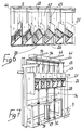
- the machine for assembling units composed of plates and separators particularly for forming electric accumulators comprises, in its present embodiment, a first frame 1 which supports a plurality of leading sectors 2 composed of inclined planes, advantageously made of sheet metal, which are parallel and equally spaced with respect to one another and arranged transversely.
- Said loading sectors 2 are each longitudinally traversed by a groove 3 from which two spaced teeth, respectively 4 and 5, can protrude; said teeth are rigidly associated radially with a small shaft 6 arranged below each sector.
- the shafts 6 are driven in synchronous half-rotation and axial translatory motion by means such as pneumatic and/or hydraulic cylinders, and mechanical connections, not shown in the drawing figures for clarification purposes.
- This movement is controlled by two proximity sensors arranged at the ends of the loading sectors 2.
- Two second parallelepipedal frames advantageously made of tubular and planar elements, respectively indicated at 7 and 8, are provided at opposite longitudinal sides of the loading sectors 2.
- a support for feeding separators having inclined planes respectively indicated by the reference numerals 9 and 10, is vertically slideable along guides inside each of said second frames.
- This vertical sliding movement is obtained by means of two first oil-dynamic cylinders 11 and 11a arranged inside the frames 7 and 8, expediently provided with pulleys, and with tension elements, not shown in the drawing figures for clarification purposes, rigidly coupled at their ends with said feed supports.
- Plates 13 and 14 are upwardly associated with said frames 7 and 8, e.g. by bolting, and respectively support two first substantially vertical pneumatic cylinders 15 and 16; an electromagnetic cylinder 17 is downwardly rigidly coupled between the protruding stems of said first cylinders 15, 16.
- a tubular element 18, closed at its ends, being arranged parallel to and below said electromagnetic cylinder 17, and an upper planar base 19, adapted for supporting a power source such as an electric motor 20 axially connected to the blades of a centrifugal vacuum pump 21, are slideably associated with said electromagnetic cylinder.
- the intake of said pump 21 is connected, by means of two divergent tubes respectively indicated by the reference numerals 22 and 23, to the inside of said tubular element 18 from which a plurality of cylindrical tubes 24 downwardly protrudes, which are provided, at their ends, with suckers 25 in rubber-like material.
- a third advantageously tubular frame 33 is arranged at the rear part of the machine and internally supports, in a transverse position, a tubular element 34 having an essentially rectangular cross section and being slideable transversely to its longitudinal axis on a horizontal plane between a position above said inclined planes 26 and a position above an accumulation means preferably comprising, for instance, a trolley or the end plane of a conveyor belt, not shown in the drawing figures for clarification purposes.
- the movement of said tubular element 34 is obtained by coupling thereto the ends of a tension element 35 extending between two pulleys, respectively 36 and 37, rotoidally linked to the ends of a fourth hydraulic or oil-dynamic cylinder 38, which causes sliding movement of said tension element by means of the movement of its inner piston.
- Said tubular element 34 during sliding, is rigidly and transversely linked to guides, respectively 39, 40 and 41, rigidly coupled to the frame.
- tubular element 34 there is a pair of second pneumatic cylinders, respectively indicated by the reference numerals 42 and 43, which raise and lower a longitudinal L-shaped profiled element 44, arranged downwardly and having coupled thereto substantially vertical plates 45, each terminating at the rollers of one of the inclined planes 26.
- a pair of third pneumatic cylinders is arranged above said tubular element 34 and is adapted to lower and raise a lower plate 48, rigidly associated with vertical bars 49, arranged parallel to said plates 45 and adjacent to the end of said rollers of said planes 26.
- Dust collection bases connected to individual aspirators or to a general aspirating network, may be provided.
- the operation of the machine is as follows: a series of plates, taken from pallets previously placed proximate to the machine, is loaded onto the front ends of the loading sectors 2, one plate for each sector. Such loading operation may obviously be effected either manually or automated.
- the automatic translatory motion of said plates towards the rear part of the loading sectors 2 is controlled by means of the two proximity sensors located at the lateral ends of said loading sectors, so that said plates are aligned with the separators located on the feeding supports 9 and 10.
- This translatory motion is then effected by means of the teeth 4 and 5 which are caused to protrude from the grooves 3 provided on the loading sectors 2 and then caused to move.
- the front part of the loading sectors 2 is ready for a new loading operation.
- tubular element 18, guided or driven by the electromagnetic cylinder 17 is already positioned so that the suckers 25 are arranged at each row of separators accumulated above one of the two feeding supports 9 or 10.
- the tubular element 18 is then caused to lower by means of the two first pneumatic cylinders 15 and 16 until the suckers 25 each make contact with one of the separators.
- the gripping of these separators is obtained in negative pressure by means of the vacuum pump 21 which sucks air from the inside of the tubes 24 and the tubular element 18.
- the feed supports 9 and 10 are automatically and independently controlled so that the upper level of the separators is constant.
- the subsequent operation is the translatory motion of the plates with separator from the rear part of the loading sectors 2 to the pluralities of rollers associated with the series of planes 26 by means of the teeth 4 and 5 which are caused to again protrude from the slots 3 and to move.
- the planes 26 are supported by the base 28 which, after every loading of the plates with separators, is caused to descend by means of the third oil-dynamic cylinder 29 so as to keep the upper edge at a constant level, thus allowing the plate-separator pairs arriving from the loading sectors 2 to be deposited gently, the plates being always placed on top of the already deposited separators.
- the plates 45 are kept in a raised position by the second pneumatic cylinders 42 and 43 while the bars 49 are maintained in a lowered position by the third pneumatic cylinders 46 and 47 so that they constitute stop elements for said translatory motion; this is the only adjustment required by the machine.
- An appropriate counter may be provided to indicate the end of the composition desired for the units, permitting raising of the base 28 and a successive translatory motion of the completed units onto a conveyor belt, trolley, etc.
- All the movements of the machine occur in automatic sequence with respect to one another, and may possibly be controlled by a microprocessor or by a computer.
- a determining characteristic of the machine is the inclined-plane configuration of the loading, transfer, forming and accumulation sectors.
- This characteristic allows the self-alignment of the plates, even if not planar or with different dimensions and configurations, with a single adjustment.
- the machine is furthermore provided with a considerably greater accumulation ability than machines currently in use which allows greater autonomy in operation.
- the materials employed, as well as the dimensions, may be any according to the requirements.
Landscapes
- Engineering & Computer Science (AREA)
- Manufacturing & Machinery (AREA)
- Chemical & Material Sciences (AREA)
- Chemical Kinetics & Catalysis (AREA)
- Electrochemistry (AREA)
- General Chemical & Material Sciences (AREA)
- Cell Separators (AREA)
Applications Claiming Priority (2)
| Application Number | Priority Date | Filing Date | Title |
|---|---|---|---|
| IT41629/87A IT1220030B (it) | 1987-07-08 | 1987-07-08 | Macchina di assemblaggio gruppi composti da placche e separatori particolarmente per la formazione di accumulatori elettrici |
| IT4162987 | 1987-07-08 |
Publications (1)
| Publication Number | Publication Date |
|---|---|
| EP0298366A1 true EP0298366A1 (de) | 1989-01-11 |
Family
ID=11252231
Family Applications (1)
| Application Number | Title | Priority Date | Filing Date |
|---|---|---|---|
| EP88110457A Withdrawn EP0298366A1 (de) | 1987-07-08 | 1988-06-30 | Maschine zum Stapeln von aus Platten und Scheidern bestehenden Einheiten, insbesondere für die Herstellung elektrischer Akkumulatoren |
Country Status (2)
| Country | Link |
|---|---|
| EP (1) | EP0298366A1 (de) |
| IT (1) | IT1220030B (de) |
Citations (3)
| Publication number | Priority date | Publication date | Assignee | Title |
|---|---|---|---|---|
| US3052968A (en) * | 1959-12-23 | 1962-09-11 | Electric Storage Battery Co | Battery separator positioning machine |
| US3443706A (en) * | 1963-04-03 | 1969-05-13 | Aga Elbab Batteriewerke Gmbh | Method for arranging a plurality of platelike elements from different supplies in a predetermined sequence |
| GB1200182A (en) * | 1966-12-15 | 1970-07-29 | Lucas Industries Ltd | Apparatus for assembling battery plate packs |
-
1987
- 1987-07-08 IT IT41629/87A patent/IT1220030B/it active
-
1988
- 1988-06-30 EP EP88110457A patent/EP0298366A1/de not_active Withdrawn
Patent Citations (3)
| Publication number | Priority date | Publication date | Assignee | Title |
|---|---|---|---|---|
| US3052968A (en) * | 1959-12-23 | 1962-09-11 | Electric Storage Battery Co | Battery separator positioning machine |
| US3443706A (en) * | 1963-04-03 | 1969-05-13 | Aga Elbab Batteriewerke Gmbh | Method for arranging a plurality of platelike elements from different supplies in a predetermined sequence |
| GB1200182A (en) * | 1966-12-15 | 1970-07-29 | Lucas Industries Ltd | Apparatus for assembling battery plate packs |
Also Published As
| Publication number | Publication date |
|---|---|
| IT8741629A0 (it) | 1987-07-08 |
| IT1220030B (it) | 1990-06-06 |
Similar Documents
| Publication | Publication Date | Title |
|---|---|---|
| CN110697395B (zh) | 一种蓄电池生产用的自动收片装置 | |
| CN108128624A (zh) | 一种全自动柜式料仓 | |
| CN118108020B (zh) | 一种可以实现自动分拣和码放的智能料箱机器人 | |
| CN110429768A (zh) | 一种微型电机的生产设备 | |
| CN113086301A (zh) | 一种真空采血管装盘设备及方法 | |
| GB2092117A (en) | Apparatus for transferring battery plates from one location to another | |
| CN214692196U (zh) | 一种托盘自动上下料装置 | |
| EP0298366A1 (de) | Maschine zum Stapeln von aus Platten und Scheidern bestehenden Einheiten, insbesondere für die Herstellung elektrischer Akkumulatoren | |
| JP2000510083A (ja) | パイル交換装置 | |
| CN112811198B (zh) | 一种智能堆垛及分离装置 | |
| CN214608222U (zh) | 纺织皮辊自动装盘装置 | |
| AT394644B (de) | Vorrichtung zum zusammensetzen von platten und separatoren zu plattenbloecken fuer akkumulatoren | |
| CN105862183A (zh) | 整体锡林梳理齿片的自动排齿机 | |
| CN114572467A (zh) | 一种电池的自动包装生产线 | |
| JPH10322088A (ja) | トレイ供給機 | |
| CN113953204A (zh) | 一种药盒自动识别分拣装置及其工作方法 | |
| CN116534358B (zh) | 菌棒自动下架脱袋码垛装置 | |
| CN214988748U (zh) | 一种智能分离装置 | |
| CN216072392U (zh) | 层叠式收集装置 | |
| CN111114891A (zh) | 一种纸杯叠放包装用投放装置 | |
| CN112977913B (zh) | 纺织皮辊自动装盘装置 | |
| CN211971045U (zh) | 一种收料装置 | |
| CN210260295U (zh) | 一种片状物料插片机 | |
| US4850781A (en) | Zero cycle interrupt wicket stacker | |
| CN214455114U (zh) | 一种智能堆垛及分离装置 |
Legal Events
| Date | Code | Title | Description |
|---|---|---|---|
| PUAI | Public reference made under article 153(3) epc to a published international application that has entered the european phase |
Free format text: ORIGINAL CODE: 0009012 |
|
| AK | Designated contracting states |
Kind code of ref document: A1 Designated state(s): DE FR GB IT |
|
| 17P | Request for examination filed |
Effective date: 19890609 |
|
| STAA | Information on the status of an ep patent application or granted ep patent |
Free format text: STATUS: THE APPLICATION IS DEEMED TO BE WITHDRAWN |
|
| 18D | Application deemed to be withdrawn |
Effective date: 19910103 |