EP0298024B2 - Reinforcing element - Google Patents
Reinforcing element Download PDFInfo
- Publication number
- EP0298024B2 EP0298024B2 EP19880810385 EP88810385A EP0298024B2 EP 0298024 B2 EP0298024 B2 EP 0298024B2 EP 19880810385 EP19880810385 EP 19880810385 EP 88810385 A EP88810385 A EP 88810385A EP 0298024 B2 EP0298024 B2 EP 0298024B2
- Authority
- EP
- European Patent Office
- Prior art keywords
- layer
- strengthening
- strengthening member
- member according
- resin
- Prior art date
- Legal status (The legal status is an assumption and is not a legal conclusion. Google has not performed a legal analysis and makes no representation as to the accuracy of the status listed.)
- Expired - Lifetime
Links
- 230000003014 reinforcing effect Effects 0.000 title description 16
- 229920001187 thermosetting polymer Polymers 0.000 claims abstract description 22
- 230000001681 protective effect Effects 0.000 claims abstract description 19
- 229920003002 synthetic resin Polymers 0.000 claims abstract description 9
- 239000000057 synthetic resin Substances 0.000 claims abstract description 9
- 229920005989 resin Polymers 0.000 claims description 51
- 239000011347 resin Substances 0.000 claims description 51
- 239000004831 Hot glue Substances 0.000 claims description 23
- 239000000463 material Substances 0.000 claims description 17
- -1 polypropylene Polymers 0.000 claims description 12
- 229920001169 thermoplastic Polymers 0.000 claims description 9
- 239000004416 thermosoftening plastic Substances 0.000 claims description 9
- 239000004744 fabric Substances 0.000 claims description 8
- 229920000647 polyepoxide Polymers 0.000 claims description 8
- 239000003822 epoxy resin Substances 0.000 claims description 7
- 239000003365 glass fiber Substances 0.000 claims description 7
- 239000000945 filler Substances 0.000 claims description 6
- 239000000203 mixture Substances 0.000 claims description 6
- 240000008564 Boehmeria nivea Species 0.000 claims description 5
- 229920001634 Copolyester Polymers 0.000 claims description 5
- 240000000491 Corchorus aestuans Species 0.000 claims description 5
- 235000011777 Corchorus aestuans Nutrition 0.000 claims description 5
- 235000010862 Corchorus capsularis Nutrition 0.000 claims description 5
- 239000004743 Polypropylene Substances 0.000 claims description 5
- 239000000853 adhesive Substances 0.000 claims description 5
- 230000001070 adhesive effect Effects 0.000 claims description 5
- 239000004760 aramid Substances 0.000 claims description 5
- 229920001155 polypropylene Polymers 0.000 claims description 5
- 239000004698 Polyethylene Substances 0.000 claims description 4
- 229920006223 adhesive resin Polymers 0.000 claims description 4
- 238000004519 manufacturing process Methods 0.000 claims description 4
- 229920000573 polyethylene Polymers 0.000 claims description 4
- 239000004840 adhesive resin Substances 0.000 claims description 3
- 239000010445 mica Substances 0.000 claims description 3
- 229910052618 mica group Inorganic materials 0.000 claims description 3
- 229920000728 polyester Polymers 0.000 claims description 3
- 239000000454 talc Substances 0.000 claims description 3
- 229910052623 talc Inorganic materials 0.000 claims description 3
- 235000012222 talc Nutrition 0.000 claims description 3
- 229910052782 aluminium Inorganic materials 0.000 claims description 2
- XAGFODPZIPBFFR-UHFFFAOYSA-N aluminium Chemical compound [Al] XAGFODPZIPBFFR-UHFFFAOYSA-N 0.000 claims description 2
- 229920002635 polyurethane Polymers 0.000 claims description 2
- 239000004814 polyurethane Substances 0.000 claims description 2
- 239000010456 wollastonite Substances 0.000 claims description 2
- 229910052882 wollastonite Inorganic materials 0.000 claims description 2
- 238000005728 strengthening Methods 0.000 claims 31
- OKTJSMMVPCPJKN-UHFFFAOYSA-N Carbon Chemical compound [C] OKTJSMMVPCPJKN-UHFFFAOYSA-N 0.000 claims 4
- 229920003235 aromatic polyamide Polymers 0.000 claims 4
- 229910052799 carbon Inorganic materials 0.000 claims 4
- 239000011521 glass Substances 0.000 claims 3
- 239000004411 aluminium Substances 0.000 claims 1
- 150000002118 epoxides Chemical class 0.000 claims 1
- 238000010438 heat treatment Methods 0.000 abstract description 35
- 239000002184 metal Substances 0.000 abstract description 10
- 229910052751 metal Inorganic materials 0.000 abstract description 10
- 238000000034 method Methods 0.000 abstract description 4
- 150000002739 metals Chemical class 0.000 abstract 1
- 239000002991 molded plastic Substances 0.000 abstract 1
- 239000000088 plastic resin Substances 0.000 abstract 1
- 239000010410 layer Substances 0.000 description 70
- 239000010408 film Substances 0.000 description 30
- 238000002844 melting Methods 0.000 description 4
- 230000008018 melting Effects 0.000 description 4
- 125000005396 acrylic acid ester group Chemical group 0.000 description 3
- 239000012790 adhesive layer Substances 0.000 description 3
- 239000013039 cover film Substances 0.000 description 3
- 239000007788 liquid Substances 0.000 description 3
- 239000004033 plastic Substances 0.000 description 3
- 229920003023 plastic Polymers 0.000 description 3
- 239000012744 reinforcing agent Substances 0.000 description 3
- 229920000049 Carbon (fiber) Polymers 0.000 description 2
- 239000004593 Epoxy Substances 0.000 description 2
- 150000001253 acrylic acids Chemical group 0.000 description 2
- 239000002313 adhesive film Substances 0.000 description 2
- 229920006231 aramid fiber Polymers 0.000 description 2
- IISBACLAFKSPIT-UHFFFAOYSA-N bisphenol A Chemical compound C=1C=C(O)C=CC=1C(C)(C)C1=CC=C(O)C=C1 IISBACLAFKSPIT-UHFFFAOYSA-N 0.000 description 2
- 239000004917 carbon fiber Substances 0.000 description 2
- 239000002131 composite material Substances 0.000 description 2
- 238000011109 contamination Methods 0.000 description 2
- 230000000694 effects Effects 0.000 description 2
- LNEPOXFFQSENCJ-UHFFFAOYSA-N haloperidol Chemical compound C1CC(O)(C=2C=CC(Cl)=CC=2)CCN1CCCC(=O)C1=CC=C(F)C=C1 LNEPOXFFQSENCJ-UHFFFAOYSA-N 0.000 description 2
- 238000013007 heat curing Methods 0.000 description 2
- 238000010137 moulding (plastic) Methods 0.000 description 2
- 230000000704 physical effect Effects 0.000 description 2
- 229920000642 polymer Polymers 0.000 description 2
- 238000003825 pressing Methods 0.000 description 2
- 229920006300 shrink film Polymers 0.000 description 2
- 239000004952 Polyamide Substances 0.000 description 1
- 239000004820 Pressure-sensitive adhesive Substances 0.000 description 1
- 239000002253 acid Substances 0.000 description 1
- 230000004913 activation Effects 0.000 description 1
- 230000002730 additional effect Effects 0.000 description 1
- 239000000654 additive Substances 0.000 description 1
- 238000004026 adhesive bonding Methods 0.000 description 1
- 125000003118 aryl group Chemical group 0.000 description 1
- 229940106691 bisphenol a Drugs 0.000 description 1
- DQXBYHZEEUGOBF-UHFFFAOYSA-N but-3-enoic acid;ethene Chemical compound C=C.OC(=O)CC=C DQXBYHZEEUGOBF-UHFFFAOYSA-N 0.000 description 1
- 238000005260 corrosion Methods 0.000 description 1
- 230000007797 corrosion Effects 0.000 description 1
- 230000001419 dependent effect Effects 0.000 description 1
- QGBSISYHAICWAH-UHFFFAOYSA-N dicyandiamide Chemical compound NC(N)=NC#N QGBSISYHAICWAH-UHFFFAOYSA-N 0.000 description 1
- 238000001035 drying Methods 0.000 description 1
- 125000003700 epoxy group Chemical group 0.000 description 1
- 239000005038 ethylene vinyl acetate Substances 0.000 description 1
- 238000011010 flushing procedure Methods 0.000 description 1
- 238000009472 formulation Methods 0.000 description 1
- 239000011256 inorganic filler Substances 0.000 description 1
- 229910003475 inorganic filler Inorganic materials 0.000 description 1
- FPYJFEHAWHCUMM-UHFFFAOYSA-N maleic anhydride Chemical group O=C1OC(=O)C=C1 FPYJFEHAWHCUMM-UHFFFAOYSA-N 0.000 description 1
- 239000003973 paint Substances 0.000 description 1
- 239000004014 plasticizer Substances 0.000 description 1
- 229920001200 poly(ethylene-vinyl acetate) Polymers 0.000 description 1
- 229920002647 polyamide Polymers 0.000 description 1
- 239000004848 polyfunctional curative Substances 0.000 description 1
- 230000037452 priming Effects 0.000 description 1
- 239000011241 protective layer Substances 0.000 description 1
- 230000002787 reinforcement Effects 0.000 description 1
- 239000012779 reinforcing material Substances 0.000 description 1
- 239000007787 solid Substances 0.000 description 1
- 238000007669 thermal treatment Methods 0.000 description 1
- 238000005406 washing Methods 0.000 description 1
- 239000002759 woven fabric Substances 0.000 description 1
Images
Classifications
-
- C—CHEMISTRY; METALLURGY
- C09—DYES; PAINTS; POLISHES; NATURAL RESINS; ADHESIVES; COMPOSITIONS NOT OTHERWISE PROVIDED FOR; APPLICATIONS OF MATERIALS NOT OTHERWISE PROVIDED FOR
- C09J—ADHESIVES; NON-MECHANICAL ASPECTS OF ADHESIVE PROCESSES IN GENERAL; ADHESIVE PROCESSES NOT PROVIDED FOR ELSEWHERE; USE OF MATERIALS AS ADHESIVES
- C09J5/00—Adhesive processes in general; Adhesive processes not provided for elsewhere, e.g. relating to primers
- C09J5/06—Adhesive processes in general; Adhesive processes not provided for elsewhere, e.g. relating to primers involving heating of the applied adhesive
-
- B—PERFORMING OPERATIONS; TRANSPORTING
- B62—LAND VEHICLES FOR TRAVELLING OTHERWISE THAN ON RAILS
- B62D—MOTOR VEHICLES; TRAILERS
- B62D29/00—Superstructures, understructures, or sub-units thereof, characterised by the material thereof
- B62D29/04—Superstructures, understructures, or sub-units thereof, characterised by the material thereof predominantly of synthetic material
-
- B—PERFORMING OPERATIONS; TRANSPORTING
- B29—WORKING OF PLASTICS; WORKING OF SUBSTANCES IN A PLASTIC STATE IN GENERAL
- B29C—SHAPING OR JOINING OF PLASTICS; SHAPING OF MATERIAL IN A PLASTIC STATE, NOT OTHERWISE PROVIDED FOR; AFTER-TREATMENT OF THE SHAPED PRODUCTS, e.g. REPAIRING
- B29C37/00—Component parts, details, accessories or auxiliary operations, not covered by group B29C33/00 or B29C35/00
- B29C37/0067—Using separating agents during or after moulding; Applying separating agents on preforms or articles, e.g. to prevent sticking to each other
- B29C37/0075—Using separating agents during or after moulding; Applying separating agents on preforms or articles, e.g. to prevent sticking to each other using release sheets
-
- B—PERFORMING OPERATIONS; TRANSPORTING
- B32—LAYERED PRODUCTS
- B32B—LAYERED PRODUCTS, i.e. PRODUCTS BUILT-UP OF STRATA OF FLAT OR NON-FLAT, e.g. CELLULAR OR HONEYCOMB, FORM
- B32B27/00—Layered products comprising a layer of synthetic resin
- B32B27/12—Layered products comprising a layer of synthetic resin next to a fibrous or filamentary layer
-
- B—PERFORMING OPERATIONS; TRANSPORTING
- B32—LAYERED PRODUCTS
- B32B—LAYERED PRODUCTS, i.e. PRODUCTS BUILT-UP OF STRATA OF FLAT OR NON-FLAT, e.g. CELLULAR OR HONEYCOMB, FORM
- B32B3/00—Layered products comprising a layer with external or internal discontinuities or unevennesses, or a layer of non-planar shape; Layered products comprising a layer having particular features of form
- B32B3/26—Layered products comprising a layer with external or internal discontinuities or unevennesses, or a layer of non-planar shape; Layered products comprising a layer having particular features of form characterised by a particular shape of the outline of the cross-section of a continuous layer; characterised by a layer with cavities or internal voids ; characterised by an apertured layer
- B32B3/266—Layered products comprising a layer with external or internal discontinuities or unevennesses, or a layer of non-planar shape; Layered products comprising a layer having particular features of form characterised by a particular shape of the outline of the cross-section of a continuous layer; characterised by a layer with cavities or internal voids ; characterised by an apertured layer characterised by an apertured layer, the apertures going through the whole thickness of the layer, e.g. expanded metal, perforated layer, slit layer regular cells B32B3/12
-
- C—CHEMISTRY; METALLURGY
- C09—DYES; PAINTS; POLISHES; NATURAL RESINS; ADHESIVES; COMPOSITIONS NOT OTHERWISE PROVIDED FOR; APPLICATIONS OF MATERIALS NOT OTHERWISE PROVIDED FOR
- C09J—ADHESIVES; NON-MECHANICAL ASPECTS OF ADHESIVE PROCESSES IN GENERAL; ADHESIVE PROCESSES NOT PROVIDED FOR ELSEWHERE; USE OF MATERIALS AS ADHESIVES
- C09J7/00—Adhesives in the form of films or foils
- C09J7/20—Adhesives in the form of films or foils characterised by their carriers
- C09J7/22—Plastics; Metallised plastics
-
- C—CHEMISTRY; METALLURGY
- C09—DYES; PAINTS; POLISHES; NATURAL RESINS; ADHESIVES; COMPOSITIONS NOT OTHERWISE PROVIDED FOR; APPLICATIONS OF MATERIALS NOT OTHERWISE PROVIDED FOR
- C09J—ADHESIVES; NON-MECHANICAL ASPECTS OF ADHESIVE PROCESSES IN GENERAL; ADHESIVE PROCESSES NOT PROVIDED FOR ELSEWHERE; USE OF MATERIALS AS ADHESIVES
- C09J7/00—Adhesives in the form of films or foils
- C09J7/30—Adhesives in the form of films or foils characterised by the adhesive composition
- C09J7/35—Heat-activated
-
- B—PERFORMING OPERATIONS; TRANSPORTING
- B32—LAYERED PRODUCTS
- B32B—LAYERED PRODUCTS, i.e. PRODUCTS BUILT-UP OF STRATA OF FLAT OR NON-FLAT, e.g. CELLULAR OR HONEYCOMB, FORM
- B32B2260/00—Layered product comprising an impregnated, embedded, or bonded layer wherein the layer comprises an impregnation, embedding, or binder material
- B32B2260/02—Composition of the impregnated, bonded or embedded layer
- B32B2260/021—Fibrous or filamentary layer
-
- B—PERFORMING OPERATIONS; TRANSPORTING
- B32—LAYERED PRODUCTS
- B32B—LAYERED PRODUCTS, i.e. PRODUCTS BUILT-UP OF STRATA OF FLAT OR NON-FLAT, e.g. CELLULAR OR HONEYCOMB, FORM
- B32B2260/00—Layered product comprising an impregnated, embedded, or bonded layer wherein the layer comprises an impregnation, embedding, or binder material
- B32B2260/04—Impregnation, embedding, or binder material
- B32B2260/046—Synthetic resin
-
- B—PERFORMING OPERATIONS; TRANSPORTING
- B32—LAYERED PRODUCTS
- B32B—LAYERED PRODUCTS, i.e. PRODUCTS BUILT-UP OF STRATA OF FLAT OR NON-FLAT, e.g. CELLULAR OR HONEYCOMB, FORM
- B32B2307/00—Properties of the layers or laminate
- B32B2307/70—Other properties
- B32B2307/732—Dimensional properties
- B32B2307/734—Dimensional stability
- B32B2307/736—Shrinkable
-
- B—PERFORMING OPERATIONS; TRANSPORTING
- B32—LAYERED PRODUCTS
- B32B—LAYERED PRODUCTS, i.e. PRODUCTS BUILT-UP OF STRATA OF FLAT OR NON-FLAT, e.g. CELLULAR OR HONEYCOMB, FORM
- B32B2605/00—Vehicles
- B32B2605/003—Interior finishings
-
- B—PERFORMING OPERATIONS; TRANSPORTING
- B32—LAYERED PRODUCTS
- B32B—LAYERED PRODUCTS, i.e. PRODUCTS BUILT-UP OF STRATA OF FLAT OR NON-FLAT, e.g. CELLULAR OR HONEYCOMB, FORM
- B32B2605/00—Vehicles
- B32B2605/08—Cars
-
- C—CHEMISTRY; METALLURGY
- C09—DYES; PAINTS; POLISHES; NATURAL RESINS; ADHESIVES; COMPOSITIONS NOT OTHERWISE PROVIDED FOR; APPLICATIONS OF MATERIALS NOT OTHERWISE PROVIDED FOR
- C09J—ADHESIVES; NON-MECHANICAL ASPECTS OF ADHESIVE PROCESSES IN GENERAL; ADHESIVE PROCESSES NOT PROVIDED FOR ELSEWHERE; USE OF MATERIALS AS ADHESIVES
- C09J2301/00—Additional features of adhesives in the form of films or foils
- C09J2301/10—Additional features of adhesives in the form of films or foils characterized by the structural features of the adhesive tape or sheet
- C09J2301/18—Additional features of adhesives in the form of films or foils characterized by the structural features of the adhesive tape or sheet characterized by perforations in the adhesive tape
-
- C—CHEMISTRY; METALLURGY
- C09—DYES; PAINTS; POLISHES; NATURAL RESINS; ADHESIVES; COMPOSITIONS NOT OTHERWISE PROVIDED FOR; APPLICATIONS OF MATERIALS NOT OTHERWISE PROVIDED FOR
- C09J—ADHESIVES; NON-MECHANICAL ASPECTS OF ADHESIVE PROCESSES IN GENERAL; ADHESIVE PROCESSES NOT PROVIDED FOR ELSEWHERE; USE OF MATERIALS AS ADHESIVES
- C09J2301/00—Additional features of adhesives in the form of films or foils
- C09J2301/20—Additional features of adhesives in the form of films or foils characterized by the structural features of the adhesive itself
- C09J2301/208—Additional features of adhesives in the form of films or foils characterized by the structural features of the adhesive itself the adhesive layer being constituted by at least two or more adjacent or superposed adhesive layers, e.g. multilayer adhesive
-
- C—CHEMISTRY; METALLURGY
- C09—DYES; PAINTS; POLISHES; NATURAL RESINS; ADHESIVES; COMPOSITIONS NOT OTHERWISE PROVIDED FOR; APPLICATIONS OF MATERIALS NOT OTHERWISE PROVIDED FOR
- C09J—ADHESIVES; NON-MECHANICAL ASPECTS OF ADHESIVE PROCESSES IN GENERAL; ADHESIVE PROCESSES NOT PROVIDED FOR ELSEWHERE; USE OF MATERIALS AS ADHESIVES
- C09J2463/00—Presence of epoxy resin
-
- C—CHEMISTRY; METALLURGY
- C09—DYES; PAINTS; POLISHES; NATURAL RESINS; ADHESIVES; COMPOSITIONS NOT OTHERWISE PROVIDED FOR; APPLICATIONS OF MATERIALS NOT OTHERWISE PROVIDED FOR
- C09J—ADHESIVES; NON-MECHANICAL ASPECTS OF ADHESIVE PROCESSES IN GENERAL; ADHESIVE PROCESSES NOT PROVIDED FOR ELSEWHERE; USE OF MATERIALS AS ADHESIVES
- C09J2467/00—Presence of polyester
-
- C—CHEMISTRY; METALLURGY
- C09—DYES; PAINTS; POLISHES; NATURAL RESINS; ADHESIVES; COMPOSITIONS NOT OTHERWISE PROVIDED FOR; APPLICATIONS OF MATERIALS NOT OTHERWISE PROVIDED FOR
- C09J—ADHESIVES; NON-MECHANICAL ASPECTS OF ADHESIVE PROCESSES IN GENERAL; ADHESIVE PROCESSES NOT PROVIDED FOR ELSEWHERE; USE OF MATERIALS AS ADHESIVES
- C09J2475/00—Presence of polyurethane
-
- Y—GENERAL TAGGING OF NEW TECHNOLOGICAL DEVELOPMENTS; GENERAL TAGGING OF CROSS-SECTIONAL TECHNOLOGIES SPANNING OVER SEVERAL SECTIONS OF THE IPC; TECHNICAL SUBJECTS COVERED BY FORMER USPC CROSS-REFERENCE ART COLLECTIONS [XRACs] AND DIGESTS
- Y10—TECHNICAL SUBJECTS COVERED BY FORMER USPC
- Y10S—TECHNICAL SUBJECTS COVERED BY FORMER USPC CROSS-REFERENCE ART COLLECTIONS [XRACs] AND DIGESTS
- Y10S174/00—Electricity: conductors and insulators
- Y10S174/08—Shrinkable tubes
-
- Y—GENERAL TAGGING OF NEW TECHNOLOGICAL DEVELOPMENTS; GENERAL TAGGING OF CROSS-SECTIONAL TECHNOLOGIES SPANNING OVER SEVERAL SECTIONS OF THE IPC; TECHNICAL SUBJECTS COVERED BY FORMER USPC CROSS-REFERENCE ART COLLECTIONS [XRACs] AND DIGESTS
- Y10—TECHNICAL SUBJECTS COVERED BY FORMER USPC
- Y10S—TECHNICAL SUBJECTS COVERED BY FORMER USPC CROSS-REFERENCE ART COLLECTIONS [XRACs] AND DIGESTS
- Y10S264/00—Plastic and nonmetallic article shaping or treating: processes
- Y10S264/65—Processes of preheating prior to molding
-
- Y—GENERAL TAGGING OF NEW TECHNOLOGICAL DEVELOPMENTS; GENERAL TAGGING OF CROSS-SECTIONAL TECHNOLOGIES SPANNING OVER SEVERAL SECTIONS OF THE IPC; TECHNICAL SUBJECTS COVERED BY FORMER USPC CROSS-REFERENCE ART COLLECTIONS [XRACs] AND DIGESTS
- Y10—TECHNICAL SUBJECTS COVERED BY FORMER USPC
- Y10S—TECHNICAL SUBJECTS COVERED BY FORMER USPC CROSS-REFERENCE ART COLLECTIONS [XRACs] AND DIGESTS
- Y10S428/00—Stock material or miscellaneous articles
- Y10S428/913—Material designed to be responsive to temperature, light, moisture
-
- Y—GENERAL TAGGING OF NEW TECHNOLOGICAL DEVELOPMENTS; GENERAL TAGGING OF CROSS-SECTIONAL TECHNOLOGIES SPANNING OVER SEVERAL SECTIONS OF THE IPC; TECHNICAL SUBJECTS COVERED BY FORMER USPC CROSS-REFERENCE ART COLLECTIONS [XRACs] AND DIGESTS
- Y10—TECHNICAL SUBJECTS COVERED BY FORMER USPC
- Y10T—TECHNICAL SUBJECTS COVERED BY FORMER US CLASSIFICATION
- Y10T428/00—Stock material or miscellaneous articles
- Y10T428/16—Two dimensionally sectional layer
- Y10T428/163—Next to unitary web or sheet of equal or greater extent
-
- Y—GENERAL TAGGING OF NEW TECHNOLOGICAL DEVELOPMENTS; GENERAL TAGGING OF CROSS-SECTIONAL TECHNOLOGIES SPANNING OVER SEVERAL SECTIONS OF THE IPC; TECHNICAL SUBJECTS COVERED BY FORMER USPC CROSS-REFERENCE ART COLLECTIONS [XRACs] AND DIGESTS
- Y10—TECHNICAL SUBJECTS COVERED BY FORMER USPC
- Y10T—TECHNICAL SUBJECTS COVERED BY FORMER US CLASSIFICATION
- Y10T428/00—Stock material or miscellaneous articles
- Y10T428/24—Structurally defined web or sheet [e.g., overall dimension, etc.]
- Y10T428/24273—Structurally defined web or sheet [e.g., overall dimension, etc.] including aperture
- Y10T428/24298—Noncircular aperture [e.g., slit, diamond, rectangular, etc.]
- Y10T428/24314—Slit or elongated
-
- Y—GENERAL TAGGING OF NEW TECHNOLOGICAL DEVELOPMENTS; GENERAL TAGGING OF CROSS-SECTIONAL TECHNOLOGIES SPANNING OVER SEVERAL SECTIONS OF THE IPC; TECHNICAL SUBJECTS COVERED BY FORMER USPC CROSS-REFERENCE ART COLLECTIONS [XRACs] AND DIGESTS
- Y10—TECHNICAL SUBJECTS COVERED BY FORMER USPC
- Y10T—TECHNICAL SUBJECTS COVERED BY FORMER US CLASSIFICATION
- Y10T428/00—Stock material or miscellaneous articles
- Y10T428/24—Structurally defined web or sheet [e.g., overall dimension, etc.]
- Y10T428/24802—Discontinuous or differential coating, impregnation or bond [e.g., artwork, printing, retouched photograph, etc.]
- Y10T428/24843—Discontinuous or differential coating, impregnation or bond [e.g., artwork, printing, retouched photograph, etc.] with heat sealable or heat releasable adhesive layer
-
- Y—GENERAL TAGGING OF NEW TECHNOLOGICAL DEVELOPMENTS; GENERAL TAGGING OF CROSS-SECTIONAL TECHNOLOGIES SPANNING OVER SEVERAL SECTIONS OF THE IPC; TECHNICAL SUBJECTS COVERED BY FORMER USPC CROSS-REFERENCE ART COLLECTIONS [XRACs] AND DIGESTS
- Y10—TECHNICAL SUBJECTS COVERED BY FORMER USPC
- Y10T—TECHNICAL SUBJECTS COVERED BY FORMER US CLASSIFICATION
- Y10T428/00—Stock material or miscellaneous articles
- Y10T428/28—Web or sheet containing structurally defined element or component and having an adhesive outermost layer
- Y10T428/2813—Heat or solvent activated or sealable
-
- Y—GENERAL TAGGING OF NEW TECHNOLOGICAL DEVELOPMENTS; GENERAL TAGGING OF CROSS-SECTIONAL TECHNOLOGIES SPANNING OVER SEVERAL SECTIONS OF THE IPC; TECHNICAL SUBJECTS COVERED BY FORMER USPC CROSS-REFERENCE ART COLLECTIONS [XRACs] AND DIGESTS
- Y10—TECHNICAL SUBJECTS COVERED BY FORMER USPC
- Y10T—TECHNICAL SUBJECTS COVERED BY FORMER US CLASSIFICATION
- Y10T428/00—Stock material or miscellaneous articles
- Y10T428/31504—Composite [nonstructural laminate]
- Y10T428/31511—Of epoxy ether
- Y10T428/31515—As intermediate layer
- Y10T428/31518—Next to glass or quartz
-
- Y—GENERAL TAGGING OF NEW TECHNOLOGICAL DEVELOPMENTS; GENERAL TAGGING OF CROSS-SECTIONAL TECHNOLOGIES SPANNING OVER SEVERAL SECTIONS OF THE IPC; TECHNICAL SUBJECTS COVERED BY FORMER USPC CROSS-REFERENCE ART COLLECTIONS [XRACs] AND DIGESTS
- Y10—TECHNICAL SUBJECTS COVERED BY FORMER USPC
- Y10T—TECHNICAL SUBJECTS COVERED BY FORMER US CLASSIFICATION
- Y10T428/00—Stock material or miscellaneous articles
- Y10T428/31504—Composite [nonstructural laminate]
- Y10T428/31551—Of polyamidoester [polyurethane, polyisocyanate, polycarbamate, etc.]
- Y10T428/31598—Next to silicon-containing [silicone, cement, etc.] layer
- Y10T428/31601—Quartz or glass
-
- Y—GENERAL TAGGING OF NEW TECHNOLOGICAL DEVELOPMENTS; GENERAL TAGGING OF CROSS-SECTIONAL TECHNOLOGIES SPANNING OVER SEVERAL SECTIONS OF THE IPC; TECHNICAL SUBJECTS COVERED BY FORMER USPC CROSS-REFERENCE ART COLLECTIONS [XRACs] AND DIGESTS
- Y10—TECHNICAL SUBJECTS COVERED BY FORMER USPC
- Y10T—TECHNICAL SUBJECTS COVERED BY FORMER US CLASSIFICATION
- Y10T428/00—Stock material or miscellaneous articles
- Y10T428/31504—Composite [nonstructural laminate]
- Y10T428/31551—Of polyamidoester [polyurethane, polyisocyanate, polycarbamate, etc.]
- Y10T428/31634—Next to cellulosic
-
- Y—GENERAL TAGGING OF NEW TECHNOLOGICAL DEVELOPMENTS; GENERAL TAGGING OF CROSS-SECTIONAL TECHNOLOGIES SPANNING OVER SEVERAL SECTIONS OF THE IPC; TECHNICAL SUBJECTS COVERED BY FORMER USPC CROSS-REFERENCE ART COLLECTIONS [XRACs] AND DIGESTS
- Y10—TECHNICAL SUBJECTS COVERED BY FORMER USPC
- Y10T—TECHNICAL SUBJECTS COVERED BY FORMER US CLASSIFICATION
- Y10T428/00—Stock material or miscellaneous articles
- Y10T428/31504—Composite [nonstructural laminate]
- Y10T428/31786—Of polyester [e.g., alkyd, etc.]
-
- Y—GENERAL TAGGING OF NEW TECHNOLOGICAL DEVELOPMENTS; GENERAL TAGGING OF CROSS-SECTIONAL TECHNOLOGIES SPANNING OVER SEVERAL SECTIONS OF THE IPC; TECHNICAL SUBJECTS COVERED BY FORMER USPC CROSS-REFERENCE ART COLLECTIONS [XRACs] AND DIGESTS
- Y10—TECHNICAL SUBJECTS COVERED BY FORMER USPC
- Y10T—TECHNICAL SUBJECTS COVERED BY FORMER US CLASSIFICATION
- Y10T442/00—Fabric [woven, knitted, or nonwoven textile or cloth, etc.]
- Y10T442/10—Scrim [e.g., open net or mesh, gauze, loose or open weave or knit, etc.]
- Y10T442/184—Nonwoven scrim
- Y10T442/191—Inorganic fiber-containing scrim
-
- Y—GENERAL TAGGING OF NEW TECHNOLOGICAL DEVELOPMENTS; GENERAL TAGGING OF CROSS-SECTIONAL TECHNOLOGIES SPANNING OVER SEVERAL SECTIONS OF THE IPC; TECHNICAL SUBJECTS COVERED BY FORMER USPC CROSS-REFERENCE ART COLLECTIONS [XRACs] AND DIGESTS
- Y10—TECHNICAL SUBJECTS COVERED BY FORMER USPC
- Y10T—TECHNICAL SUBJECTS COVERED BY FORMER US CLASSIFICATION
- Y10T442/00—Fabric [woven, knitted, or nonwoven textile or cloth, etc.]
- Y10T442/60—Nonwoven fabric [i.e., nonwoven strand or fiber material]
- Y10T442/674—Nonwoven fabric with a preformed polymeric film or sheet
Definitions
- the present invention relates to a multilayer, flat stiffening body according to the preamble of claim 1.
- Such laminated bodies can be made from a first actual stiffening layer, e.g. a glass fiber fabric bonded with thermosetting resin, one surface of which is provided with a second layer of thermosetting, sticky resin.
- a composite can be used to reinforce flat and curved sheets by placing a piece of the composite with the sticky resin side on the sheet and then thermally treating it.
- the laminated body is glued to the sheet metal, and on the other hand, the resin layers are cured, so that a shear-resistant connection is created between the sheet metal and the fiber-reinforced layer. This allows a significant stiffening of the sheet metal section in question to be achieved in a simple manner without significant additional weight.
- the second resin layer is generally formed with a sticky surface, so that the stiffening body, once applied, is subjected to thermal treatment at the point in question of the sheet is liable.
- the sticky surface of the stiffening body must be provided with a protective layer until it is used, in order to protect it from contamination and to enable the stiffening body to be stacked.
- the protection is formed by a suitably treated paper or a protective film, which is removed immediately before the stiffening body is applied.
- a disadvantage here is that the removal of the protective paper or the protective film represents an undesirable, additional work step which, moreover, can hardly be carried out mechanically.
- this process of removing the protective paper or the protective film is assessed as an undesirable, time-consuming and labor-intensive process.
- stiffening body for stiffening metal sheets, plastic moldings or the like, which no longer has these disadvantages, so that there is no need to remove a protective film from the surface facing the element to be stiffened, so that
- tailored stiffening body sections can be provided, in particular stacked, without becoming dirty on the surface and sticking to one another, and then in one piece automatable process for stiffening a sheet, a plastic molded body or the like.
- US Pat. No. 4,444,818 discloses a flat reinforcing structure made of thermosetting synthetic resin, with a structure of one- or two-layer synthetic resin body with a built-in flat-shaped tube which regains its original tubular shape when cross-linked and forms a light-weight reinforcing structure, one of the layers with Reinforcement material is provided.
- Epoxy resins are mentioned as the most suitable plastics (column 4, lines 10-12) and reinforcing materials are already known to those skilled in the art (column 5, lines 21-30).
- the structure should have a sticky surface (column 5, lines 12-20) to enable the structure to be attached to metal surfaces. However, it is not possible to achieve the object of the invention.
- a strapless adhesive film is known from FR-A-2 275 539, which is not tacky at room temperature, but is tacky at elevated temperature.
- This adhesive film is in no way suitable as a reinforcing element for metal sheets or the like and is only subjected to a single heat treatment, ie it must be in the non-tacky state on the object to be bonded applied and held there under pressure until the heat treatment is complete.
- a stiffening body according to the invention can be very easily automated or carried out by a robot or the like, in that the stiffening body is first a first, e.g. can be subjected to one-sided, superficial heat treatment, then placed on the sheet to be stiffened, the molded body, etc. and finally subjected to a second heat treatment; the difficult removal of the protective paper or the protective film, as well as holding on until it cures, is eliminated.
- the basic idea of the invention is to stiffen a sheet metal, a plastic molded body or the like with the aid of a flat stiffening body without having to remove a protective paper, a protective film or the like before the stiffening body is attached to the element to be stiffened can.
- a stiffening body can be used, as is shown schematically in various versions, for example in FIGS. 1 to 13.
- the stiffening body has at least one layer of a thermosetting synthetic resin and that it is used for Production of a sticky surface has at least one heat-activatable layer.
- the thermosetting synthetic resin layer is required so that the stiffening body becomes rigid under the influence of heat and can therefore perform its stiffening function at all.
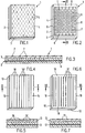
- a first embodiment of a stiffening body has a carrier layer 2, e.g. from a thermosetting synthetic resin, in which a glass fiber mat 9 is embedded and which is provided on one side with a layer 3 of thermosetting resin.
- a carrier layer 2 e.g. from a thermosetting synthetic resin, in which a glass fiber mat 9 is embedded and which is provided on one side with a layer 3 of thermosetting resin.
- a cover film 4 is provided which protects the resin surface from contamination and allows prepared, tailored stiffening bodies 1 together with the sticky resin layer 3 attached to it can be stacked on top of one another without sticking to one another.
- the resin layer 3 can be designed as a whole to be self-adhesive, or it can have a pressure-sensitive adhesive layer only on its surface facing outwards.
- the film is made from a material which shrinks when exposed to heat.
- materials are known per se and are offered in numerous different versions on the market.
- the film 4 is formed in one piece and has a multiplicity of slots 5 which are arranged offset in rows running parallel to one another and from row to row.
- the slits 5 have no influence, since they are closed, so that the same protective effect is achieved with the slotted film 4 as with a continuous film without slits.
- the stiffening body 1 If the stiffening body 1 is now to be fastened to a sheet to be reinforced, it need only be briefly subjected to a superficial heat treatment, e.g. by flaming it on the film side or by passing it through an IR radiator; the film 4 shrinks and assumes a network-like configuration, the slots 5 enlarging into oval openings 6 (FIG. 2). As a result, a considerable part of the sticky surface of the resin layer 3 is released, so that the stiffening body can be fastened, as usual, to the point to be reinforced by simply placing it on or pressing it lightly.
- a superficial heat treatment e.g. by flaming it on the film side or by passing it through an IR radiator
- the film 4 shrinks and assumes a network-like configuration, the slots 5 enlarging into oval openings 6 (FIG. 2).
- a considerable part of the sticky surface of the resin layer 3 is released, so that the stiffening body can be fastened, as usual, to the point
- the film 4 shrinks as a whole, so that 3 edge regions 8 are completely exposed along the edge of the resin layer.
- This is a highly desirable additional effect because as a result, the adhesion of the stiffening body 1 to the component to be reinforced is more pronounced in the edge region before the final heat treatment. Improved corrosion protection is thus achieved in the edge area 8, since the full-area gluing of the edge area 8 to the component to be reinforced means that there can be no undercuts with possible partial detachment of the stiffening body 1. Such flushing can possibly occur when the stiffening body 1 is attached, for example, to the inside of a car body component, which is then subjected to a washing and / or priming treatment before the final heat treatment takes place.
- thermosetting resin in the layer 3 initially becomes more liquid and flows around the remaining webs 7 of the shrunk protective film 4 (FIG. 3), so that almost the entire surface of the sticky resin layer 3 for connecting the stiffening body 1 to a sheet metal to be reinforced or the like.
- the stiffening body of the second exemplary embodiment according to FIGS. 4-7 has a similar structure, with a resin-bonded glass fiber fabric 12 to which a layer 13 of sticky, thermosetting resin is applied.
- the protective film 14, however, again made of a material that shrinks when exposed to heat, is composed of individual webs 14 'which are laid so as to abut one another and thus have the effect of a continuous film have (Fig. 4 and 5), since the individual tracks are separated by slots 18 with a minimum width.
- the effect of total shrinkage also occurs in the longitudinal direction of the remaining webs 17, so that edge regions 19 of the sticky surface of the resin layer 13 are completely released, with the resulting advantages which were explained in connection with the first exemplary embodiment.
- the heat-activatable layer provided according to the invention is formed by the combination of the resin layer 3 or 13 and the shrink film 4 or 14; the resin layer 3 or 13 is itself sticky, the activation, i.e. the sticky surface is exposed by shrinking the cover film 4 or 14.
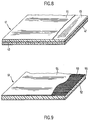
- stiffening bodies 41 and 51 are formed in two layers: on the one hand, a layer is formed from a thermosetting resin 45 provided with reinforcing agents and, on the other hand, a layer of a reactive hot-melt adhesive 42 is provided, as shown in FIG. 8.
- Corresponding layers 55 made of a thermosetting resin provided with reinforcing agents and a layer 52 of a reactive hot melt adhesive are present in the exemplary embodiment according to FIG. 9.
- the material used for the layer 45 is a heat-curing one-component epoxy resin mixture, which can optionally have already been prepolymerized.
- the layer 42 or 52 can be formed by a hot melt adhesive; an epoxy-based adhesive resin, possibly based on polyurethane or copolyester, can be used as a reactive hot-melt adhesive.
- a hot melt adhesive an epoxy-based adhesive resin, possibly based on polyurethane or copolyester, can be used as a reactive hot-melt adhesive.
- a one-component formulation with epoxy resins based on bisphenol-A and with a heat hardener, for example dicyandiamide, can be mentioned as an example.
- Such hot melt adhesives are dry at room temperature and become sticky at a temperature above approx. 60 ° C.
- the melting range can be adjusted by a suitable choice of solid resins and by adding liquid additives such as liquid epoxies, tackifier resins, plasticizers etc.
- the hot-melt adhesive layer 42 or 52 is heated to approximately 60 to 140 ° C., preferably to approximately 80 to 120 ° C., in the course of the first heat treatment. This ensures that the surface of the stiffening body 41 or 51 becomes sufficiently sticky and has sufficient heat content to reliably adhere to a sheet, even if it is only at room temperature. Even if the stiffening body 41 or 51 cools down to room temperature again, it sticks.
- the stiffening body 41 or 51 is heated to approximately 140 to 240 ° C., preferably approximately to 160 to 200 ° C. This causes the resin material to crosslink and thus harden the hot-melt adhesive resin layer 42 or 52 .
- the advantage of the embodiment according to FIGS. 8 and 9 is that they are cheap because little of the relatively expensive, reactive hot-melt adhesive material has to be used. In principle, good stiffening can also be achieved, since an optimally suitable material can be used for the actual stiffening layer with the reinforcing agents, namely a resin with a comparatively high filler content, while a material with a comparatively low filler content is used for the actual adhesive layer Not to affect the elasticity of the adhesive layer.
- a flat reinforcing body 43 is embedded in the resin layer 45, while in the exemplary embodiment according to FIG. 9, a flat reinforcing body 53 is placed on the surface of the resin layer 55 facing away from the reactive hot melt adhesive layer, optionally pressed in on the surface.
- a mat, a woven fabric, a mesh, a fleece or the like can be placed on the resin layer 55 as a flat reinforcing body 53, optionally pressed on or on the surface.
- This flat reinforcing body 53 preferably consists of glass fibers, carbon fibers, aramid fibers, jute, ramie or the like. This measure also contributes significantly to improving the physical properties of the layer 55 in the hardened state.
- the layer 45 can also be formed by impregnating the reinforcing body 43 with a low-viscosity, heat-curing epoxy resin.
- the reinforcing body 43 e.g. in the form of a glass fiber fabric, is immersed in a resin mixture in solution with a proportion of 30% to 70% fillers, pressed and dried; After the drying process, prepolymerization can optionally be carried out.
- the free surface of the stiffening body 41 or 51 can be provided with a cover film 44 or 54 made of aluminum, paper or polyester.
- thermoplastic hot-melt adhesive based on modified polypropylene, copolyamide or copolyester as layer 42 or 52.
- polypropylene polymer grafted with polar groups such as maleic anhydride, acrylic acids, acrylic acid esters or the like. These materials have a melting range of approx. 130 to 150 ° C, a heat resistance of approx. 130 to 190 ° C, depending on the load, and an application temperature of approx. 170 to 250 ° C.
- the heating takes place in the course of the first heat treatment to the application temperature of approx. 170 to 250 ° C, but only for a very short time.
- the short heat treatment reacts the resin layer 45 or 55 not yet.
- the advantage of a high application temperature is that the stiffening body 41 or 51 adheres better to sheets whose surface still has traces of oil, since the oil residues diffuse into the hot melt adhesive layer 42 or 52 due to the high temperature.
- the layer 42 of the thermoplastic hot melt adhesive can also be formed by a polyamide or polyester copolymer, which have similar properties to the aforementioned polypropylene polymers.
- thermoplastic hot melt adhesive layer 42 is preferably a film with a thickness of 0.1 to 2 mm, preferably 0.2 to 0.6 mm, to which the layer 45 or 55 made of thermosetting resin is connected.
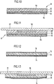
- the stiffening body is again of multilayer design and comprises a layer 65 of thermosetting epoxy resin; preferably the same resins are used as described above in connection with the exemplary embodiments according to FIGS. 8 and 9.
- the other surface of the resin layer 65 is covered with an adhesive layer 62, preferably a reactive hot melt adhesive layer as described above.
- the melting point of this layer 62 is, however, due to a suitable composition of the adhesive material, substantially lower, in particular in the range from approximately 10 to 40 ° C., so that the layer 62 is already tacky at room temperature or a slightly elevated temperature.
- Layer 62 is finally covered with a shrinking, thermoplastic hot melt adhesive film 66 which is dry at room temperature, i.e. is not sticky.
- a modified polyethylene, a modified polypropylene, a copolyamide, a copolyester, an ethylene vinyl acetate or the like can be used as the material for the film 66.
- a polyethylene grafted with aryl acid or acrylic acid esters or a polyethylene copolymerized with acrylic acids or acrylic acid esters is used.
- the film 66 shrinks after the first heat treatment and releases a significant part of the layer 62.
- the stiffening body 61 is pressed onto a sheet 67 to be stiffened, the shrunk film 66 is embedded in the layer 62.
- FIGS. 12 and 13 A variant is shown in FIGS. 12 and 13. However, the hot melt adhesive layer 62 is omitted here and the shrink film 76 lies directly on the surface of the resin layer 75.
- the composition of the resin is changed so that its melting point is comparatively high is low in order to ensure that the resin surface is already tacky in a temperature range of approx. 10 to 40 ° C.
- the reinforcing body 73 is preferably placed or pressed onto the surface of the layer 75 facing away from the film 76 and provided with a protective film 74.
- the stiffening body 71 is placed on the sheet 77 to be stiffened.
- the first heat treatment has already taken place, so that the film 76 has shrunk and releases a significant part of the sticky resin layer 75. Similar to the exemplary embodiment according to FIGS. 10 and 11, the shrunk film 76 is embedded in the resin layer 75.
- the film 66 or 76 can also be provided with slots.
- the further advantage is, however, that an adhesive effect is also achieved by the film 66 or 76 itself, since, as mentioned, it consists of a thermoplastic hot-melt adhesive material. It is therefore not necessary for the remaining webs of the shrunk, slotted film to be completely embedded in the material of the layer 62 or the resin layer 76.
- the surface of the stiffening body which is intended to adhere to the sheet to be stiffened, is dry, in particular not sticky, before the first heat treatment. That state changes after the first heat treatment; this can be carried out, for example, by means of an infrared radiator, past which the stiffening body is moved. Another possibility is to flame the surface in contact with the sheet.
- the first heat treatment can be carried out at a lower temperature than the second heat treatment, in particular to prevent the actual stiffening layer from already starting to harden.
- a thermoplastic hot-melt adhesive used as the contact layer, it is advisable to carry out the first heat treatment at the same temperature or a temperature which is even higher than that of the second heat treatment. However, it must then be ensured that the first heat treatment is carried out only for a very short time.
- the second heat treatment generally takes much longer than the first heat treatment.
- the following example can be used as a starting point: For reasons of simplicity, it is advisable, for example in the case of a freshly painted body that has to be stiffened in sections with a stiffening body, to carry out the second heat treatment in an oven, in particular in a paint baking oven. This works at a temperature of approx. 170 to 190 ° C and the burn-in time is about 30 minutes.
- a thermosetting epoxy resin can be set so that a heat treatment at 180 ° C for approx. 30 min. sufficient to fully harden the resin. This eliminates the need for a separate operation for the second heat treatment.
Landscapes
- Chemical & Material Sciences (AREA)
- Organic Chemistry (AREA)
- Engineering & Computer Science (AREA)
- Architecture (AREA)
- Structural Engineering (AREA)
- Combustion & Propulsion (AREA)
- Transportation (AREA)
- Mechanical Engineering (AREA)
- Laminated Bodies (AREA)
- Reinforced Plastic Materials (AREA)
- Manufacturing Of Tubular Articles Or Embedded Moulded Articles (AREA)
Abstract
Description
Die vorliegende Erfindung bezieht sich auf einen mehrschichtigen, flächigen Versteifungskörper nach dem Oberbegriff des Patentanspruchs 1.The present invention relates to a multilayer, flat stiffening body according to the preamble of
Gemäss dem Stand der Technik werden zum Versteifen von Blechen, Kunststoff-Formkörpern oder dgl., z.B. von Teilen von Automobilkarosserien besondere Schichtkörper verwendet. Solche Schichtkörper können aus einer ersten, eigentlichen Versteifungsschicht, z.B. einem mit wärmehärtendem Harz gebundenen Glasfasergewebe bestehen, deren eine Oberfläche mit einer zweiten Schicht aus wärmehärtendem, klebrigem Harz versehen ist. Ein derartiger Verbund kann zur Verstärkung von ebenen und gewölbten Blechen verwendet werden, indem ein Stück des Verbundes mit der klebrigen Harzseite auf das Blech aufgelegt und dann thermisch behandelt wird. Dabei erfolgt einerseits eine Verklebung des Schichtkörpers mit dem Blech, und andererseits eine Aushärtung der Harzschichten, so dass zwischen Blech und faserverstärkter Schicht eine schubsteife Verbindung entsteht. Dadurch lässt sich auf einfache Weise, ohne namhaftes zusätzliches Gewicht, eine bedeutende Versteifung der betreffenden Blechpartie erreichen.According to the prior art, for stiffening sheet metal, plastic moldings or the like, e.g. parts of automobile bodies used special laminates. Such laminated bodies can be made from a first actual stiffening layer, e.g. a glass fiber fabric bonded with thermosetting resin, one surface of which is provided with a second layer of thermosetting, sticky resin. Such a composite can be used to reinforce flat and curved sheets by placing a piece of the composite with the sticky resin side on the sheet and then thermally treating it. On the one hand, the laminated body is glued to the sheet metal, and on the other hand, the resin layers are cured, so that a shear-resistant connection is created between the sheet metal and the fiber-reinforced layer. This allows a significant stiffening of the sheet metal section in question to be achieved in a simple manner without significant additional weight.
Im Interesse einer einfachen Applikation des Versteifungskörpers bildet man die zweite Harzschicht im allgemeinen mit klebriger Oberfläche aus, so dass der einmal angebrachte Versteifungskörper bis zur thermischen Behandlung an der betreffenden Stelle des Bleches haftet. Dies bedingt aber, dass die klebrige Oberfläche des Versteifungskörpers bis zu dessen Verwendung mit einem Schutz versehen werden muss, um sie vor Verschmutzung zu schützen und ein Stapeln der Versteifungskörper zu ermöglichen. Nach dem Stand der Technik wird der Schutz durch ein geeignet behandeltes Papier oder eine Schutzfolie gebildet, die unmittelbar vor der Applikation des Versteifungskörpers abgezogen wird.In the interest of simple application of the stiffening body, the second resin layer is generally formed with a sticky surface, so that the stiffening body, once applied, is subjected to thermal treatment at the point in question of the sheet is liable. However, this means that the sticky surface of the stiffening body must be provided with a protective layer until it is used, in order to protect it from contamination and to enable the stiffening body to be stacked. According to the prior art, the protection is formed by a suitably treated paper or a protective film, which is removed immediately before the stiffening body is applied.
Ein Nachteil dabei ist, dass das Abziehen des Schutzpapiers bzw. der Schutzfolie einen unerwünschten, zusätzlichen Arbeitsgang darstellt, der sich zudem kaum maschinell ausführen lässt. Gerade in der Automobilindustrie, in der solche Versteifungskörper verwendet werden und in der das vermehrte Bestreben besteht, so weit wie möglich Arbeitsschritte zu automatisieren, wird dieser Vorgang des Abziehens des Schutzpapiers bzw. der Schutzfolie als unerwünschter, zeitraubender und personalintensiver Vorgang gewertet.A disadvantage here is that the removal of the protective paper or the protective film represents an undesirable, additional work step which, moreover, can hardly be carried out mechanically. Especially in the automotive industry, in which such stiffening bodies are used and in which there is an increased effort to automate work steps as much as possible, this process of removing the protective paper or the protective film is assessed as an undesirable, time-consuming and labor-intensive process.
Es ist die Aufgabe der Erfindung, einen Versteifungskörper zum Versteifen von Blechen, Kunststoff-Formkörpern oder dgl. anzugeben, der diese Nachteile nicht mehr aufweist, bei dem also die Entfernung einer Schutzfolie von der dem zu versteifenden Element zugewandten Oberfläche entfällt, so dass vorbereitete, z.B. zugeschnittene Versteifungskörper-Abschnitte bereitgestellt, insbesondere gestapelt werden können, ohne an der Oberfläche zu verschmutzen und aneinander zu haften, um dann in einem leicht automatisierbaren Vorgang zur Versteifung eines Bleches, eines Kunststoff-Formkörpers oder dgl. herangezogen zu werden.It is the object of the invention to provide a stiffening body for stiffening metal sheets, plastic moldings or the like, which no longer has these disadvantages, so that there is no need to remove a protective film from the surface facing the element to be stiffened, so that For example, tailored stiffening body sections can be provided, in particular stacked, without becoming dirty on the surface and sticking to one another, and then in one piece automatable process for stiffening a sheet, a plastic molded body or the like.
Gemäss der Erfindung wird dies durch die Merkmale im Kennzeichen des Anspruchs 1 bzw. des Anspruchs 5 bzw. des Anspruchs 7 erreicht.According to the invention, this is achieved by the features in the characterizing part of
Die US-PS-4 444 818 offenbart ein flächiges Verstärkungsgebilde aus wärmehärtendem Kunstharz, mit einer Struktur aus ein- oder zweischichtigem Kunstharzkörper mit einem eingebauten flachförmigen Schlauch, der bei der Vernetzung seine ursprüngliche Röhrenform wiederbekommt und ein leichtwiegendes Verstärkungsgebilde bildet, wobei eine der Schichten mit Verstärkungsmaterial versehen ist. Als best geeignete Kunststoffe werden Epoxyharze erwähnt (Spalte 4, Zeilen 10-12) und als Verstärkungsmaterialien bereits für den Fachmann bekannte Stoffe (Spalte 5, Zeilen 21-30). Das Gebilde soll eine klebrige Oberfläche aufweisen (Spalte 5, Zeilen 12-20), um das Anbringen des Gebildes auf Metalloberflächen zu ermöglichen. Damit ist es aber nicht möglich, die erfindungsgemäss gestellte Aufgabe zu lösen.US Pat. No. 4,444,818 discloses a flat reinforcing structure made of thermosetting synthetic resin, with a structure of one- or two-layer synthetic resin body with a built-in flat-shaped tube which regains its original tubular shape when cross-linked and forms a light-weight reinforcing structure, one of the layers with Reinforcement material is provided. Epoxy resins are mentioned as the most suitable plastics (column 4, lines 10-12) and reinforcing materials are already known to those skilled in the art (column 5, lines 21-30). The structure should have a sticky surface (column 5, lines 12-20) to enable the structure to be attached to metal surfaces. However, it is not possible to achieve the object of the invention.
Aus der FR-A-2 275 539 ist zwar ein trägerloser Klebefilm bekannt geworden, der bei Raumtemperatur nicht klebrig, bei erhöhter Temperatur jedoch klebrig ist. Dieser Klebefilm eignet sich in keiner Weise als Verstärkungselement für Bleche oder dgl. und wird nur einer einzigen Wärmebehandlung unterworfen, d.h. er muss im nicht-klebrigen Zustand auf den zu verklebenden Gegenstand aufgebracht und dort unter Druck festgehalten werden, bis die Wärmebehandlung abgeschlossen ist.A strapless adhesive film is known from FR-A-2 275 539, which is not tacky at room temperature, but is tacky at elevated temperature. This adhesive film is in no way suitable as a reinforcing element for metal sheets or the like and is only subjected to a single heat treatment, ie it must be in the non-tacky state on the object to be bonded applied and held there under pressure until the heat treatment is complete.
Demgegenüber lässt sich das Aufbringen eines erfindungsgemässen Versteifungskörpers sehr leicht automatisieren bzw. durch einen Roboter oder dgl. ausführen, indem der Versteifungskörper zunächst einer ersten, z.B. einseitigen, oberflächlichen Wärmebehandlung unterworfen werden kann, dann anschliessend auf das zu versteifende Blech, den Formkörper etc. aufgesetzt und schliesslich einer zweiten Wärmebehandlung unterworfen wird; das diffizile Abziehen des Schutzpapiers bzw. der Schutzfolie wie auch ein Festhalten bis zur Aushärtung entfällt.In contrast, the application of a stiffening body according to the invention can be very easily automated or carried out by a robot or the like, in that the stiffening body is first a first, e.g. can be subjected to one-sided, superficial heat treatment, then placed on the sheet to be stiffened, the molded body, etc. and finally subjected to a second heat treatment; the difficult removal of the protective paper or the protective film, as well as holding on until it cures, is eliminated.
Für die praktische Ausbildung eines solchen Versteifungskörpers bestehen verschiedene Möglichkeiten; einige davon sind in den abhängigen Ansprüchen 2-4, 6 und 8-19 umschrieben und werden im folgenden noch näher erläutert werden.There are various options for the practical training of such a stiffening body; some of them are described in dependent claims 2-4, 6 and 8-19 and will be explained in more detail below.
In den Zeichnungen zeigen:
- Fig. 1
- eine schematische, perspektivische Ansicht eines ersten Ausführungsbeispiels eines Versteifungskörpers vor einer ersten Wärmebehandlung;
- Fig. 2
- eine schematische, perspektivische Ansicht des ersten Ausführungsbeispiels des Versteifungskörpers nach der ersten Wärmebehandlung;
- Fig. 3
- einen Teilschnitt in grösserem Maßstab nach der Linie III-III in Fig. 2;
- Fig. 4
- eine schematische, perspektivische Ansicht eines zweiten Ausführungsbeispiels eines Versteifungskörpers vor einer ersten Wärmebehandlung;
- Fig. 5
- einen Teilschnitt in grösserem Maßstab nach der Linie V-V in Fig. 4;
- Fig. 6
- eine schematische, perspektivische Ansicht des zweiten Ausführungsbeispiels des Versteifungskörpers nach der ersten Wärmebehandlung;
- Fig. 7
- einen Teilschnitt in grösserem Maßstab nach der Linie VII-VII in Fig. 6;
- Fig. 8
- eine teilweise geschnittene Teilansicht eines dritten Ausführungsbeispiels eines Versteifungskörpers;
- Fig. 9
- eine teilweise geschnittene Teilansicht eines vierten Ausführungsbeispiels eines Versteifungskörpers;
- Fig. 10
- einen Schnitt durch ein fünftes Ausführungsbeispiel eines Versteifungskörpers, vor dem Anbringen an ein zu versteifendes Blech;
- Fig. 11
- einen Schnitt durch das fünfte Ausführungsbeispiel des Versteifungskörpers, nachdem er an dem zu versteifenden Blech angebracht und einer zweiten Wärmebehandlung unterzogen worden ist;
- Fig. 12
- einen Schnitt durch ein sechstes Ausführungsbeispiel eines Versteifungskörpers, vor dem Anbringen an ein zu versteifendes Blech; und
- Fig. 13
- einen Schnitt durch das sechste Ausführungsbeispiel des Versteifungskörpers, nachdem er an dem zu versteifenden Blech angebracht und einer zweiten Wärmebehandlung unterzogen worden ist.
- Fig. 1
- a schematic, perspective view of a first embodiment of a stiffening body before a first heat treatment;
- Fig. 2
- is a schematic, perspective view of the first embodiment of the stiffening body after the first heat treatment;
- Fig. 3
- a partial section on a larger scale along the line III-III in Fig. 2;
- Fig. 4
- a schematic, perspective view of a second embodiment of a stiffening body before a first heat treatment;
- Fig. 5
- a partial section on a larger scale along the line VV in Fig. 4;
- Fig. 6
- is a schematic, perspective view of the second embodiment of the stiffening body after the first heat treatment;
- Fig. 7
- a partial section on a larger scale along the line VII-VII in Fig. 6;
- Fig. 8
- a partial sectional view of a third embodiment of a stiffening body;
- Fig. 9
- a partial sectional view of a fourth embodiment of a stiffening body;
- Fig. 10
- a section through a fifth embodiment of a stiffening body, before attachment to a sheet to be stiffened;
- Fig. 11
- a section through the fifth embodiment of the stiffening body after it has been attached to the sheet to be stiffened and has undergone a second heat treatment;
- Fig. 12
- a section through a sixth embodiment of a stiffening body, before attachment to a sheet to be stiffened; and
- Fig. 13
- a section through the sixth embodiment of the stiffening body after it has been attached to the sheet to be stiffened and subjected to a second heat treatment.
Wie schon einleitend gesagt besteht der Leitgedanke der Erfindung darin, ein Blech, einen Kunststoff-Formkörper oder dergleichen mit Hilfe eines flächigen Versteifungskörpers zu versteifen, ohne dass ein Schutzpapier, eine Schutzfolie oder dergleichen entfernt werden muss, bevor der Versteifungskörper am zu versteifenden Element angebracht werden kann.As already mentioned in the introduction, the basic idea of the invention is to stiffen a sheet metal, a plastic molded body or the like with the aid of a flat stiffening body without having to remove a protective paper, a protective film or the like before the stiffening body is attached to the element to be stiffened can.
Zu diesem Zwecke kann ein Versteifungskörper verwendet werden, wie er in verschiedenen Ausführungen beispielsweise in den Fig. 1 bis 13 schematisch dargestellt ist. Wesentlich ist jedenfalls, dass der Versteifungskörper zumindest eine Schicht aus einem unter Wärmeeinfluss aushärtenden Kunstharz besitzt und dass er zur Erzeugung einer klebrigen Oberfläche mindestens eine durch Wärme aktivierbare Schicht aufweist. Die wärmehärtende Kunstharzschicht ist erforderlich, damit der Versteifungskörper unter Wärmeeinfluss starr wird und somit überhaupt seine Versteifungsfunktion ausüben kann.For this purpose, a stiffening body can be used, as is shown schematically in various versions, for example in FIGS. 1 to 13. In any case, it is essential that the stiffening body has at least one layer of a thermosetting synthetic resin and that it is used for Production of a sticky surface has at least one heat-activatable layer. The thermosetting synthetic resin layer is required so that the stiffening body becomes rigid under the influence of heat and can therefore perform its stiffening function at all.
Das in den Fig. 1-3 dargestellte, erste Ausführungsbeispiel eines generell mit 1 bezeichneten Versteifungskörpers besitzt eine Trägerschicht 2, z.B. aus einem wärmehärtenden Kunstharz, in die eine Glasfasermatte 9 eingebettet ist und die einseitig mit einer Schicht 3 aus wärmehärtendem Harz versehen ist. Da die Oberfläche der Harzschicht 3 zweckmässigerweise klebrig ausgebildet ist, um den Versteifungskörper an einem zu versteifenden Blech anbringen zu können, ohne zusätzliche Befestigungsmassnahmen zu treffen, ist eine Abdeckfolie 4 vorgesehen, die die Harzoberfläche vor Verschmutzung schützt und es erlaubt, dass vorbereitete, zugeschnittene Versteifungskörper 1 mitsamt der darauf angebrachten, klebrigen Harzschicht 3 aufeinander gestapelt werden können, ohne aneinander kleben zu bleiben.1-3, a first embodiment of a stiffening body, generally designated 1, has a
Je nach Anforderungen kann die Harzschicht 3 als ganzes selbstklebend ausgebildet sein, oder aber nur auf ihrer gegen aussen gerichteten Oberfläche eine Haftklebeschicht aufweisen.Depending on the requirements, the
Um nun das Abziehen der Schutzfolie 4 vor dem Anbringen des Versteifungskörpers 1 zu vermeiden, ist die Folie aus einem Material hergestellt, das bei Wärmeeinwirkung schrumpft. Solche Materialien sind an sich bekannt und werden in zahlreichen unterschiedlichen Ausführungen auf dem Markt angeboten.In order to prevent the protective film 4 from being pulled off before the
Gemäss dem ersten Ausführungsbeispiel nach Fig. 1 ist die Folie 4 einstückig ausgebildet und besitzt eine Vielzahl von Schlitzen 5, die in parallel zueinander verlaufenden Reihen und von Reihe zu Reihe gegeneinander versetzt angeordnet sind. In diesem Zustand haben die Schlitze 5 keinen Einfluss, da sie geschlossen sind, so dass mit der geschlitzten Folie 4 der gleiche Schutzeffekt erzielt ist wie mit einer durchgehenden Folie ohne Schlitze.According to the first exemplary embodiment according to FIG. 1, the film 4 is formed in one piece and has a multiplicity of slots 5 which are arranged offset in rows running parallel to one another and from row to row. In this state, the slits 5 have no influence, since they are closed, so that the same protective effect is achieved with the slotted film 4 as with a continuous film without slits.
Soll nun der Versteifungskörper 1 an einem zu verstärkenden Blech befestigt werden, braucht er nur kurz einer oberflächlichen Wärmebehandlung unterzogen zu werden, z.B. dadurch, dass er folienseitig beflammt oder an einem IR-Strahler vorbeigeführt wird; dabei schrumpft die Folie 4 und nimmt eine netzartige Konfiguration ein, wobei sich die Schlitze 5 zu ovalen Öffnungen 6 vergrössern (Fig. 2). Dadurch wird ein erheblicher Teil der klebrigen Oberfläche der Harzschicht 3 freigesetzt, so dass der Versteifungskörper wie üblich an der zu verstärkenden Stelle durch einfaches Auflegen bzw. leichtes Andrücken befestigt werden kann.If the
Ausserdem schrumpft die Folie 4 als Ganzes, so dass entlang des Randes der Harzschicht 3 Randbereiche 8 vollständig freigelegt werden. Dies ist ein höchst erwünschter, zusätzlicher Effekt, da dadurch die Haftung des Versteifungskörpers 1, vor der abschliessenden Wärmebehandlung, am zu verstärkenden Bauteil im Randbereich ausgeprägter ist. Damit wird ein verbesserter Korrosionsschutz im Randbereich 8 erreicht, indem durch das vollflächige Verkleben des Randbereiches 8 am zu verstärkenden Bauteil keine Unterspülungen mit eventueller, partieller Ablösung des Versteifungskörpers 1 vorkommen können. Derartige Unterspülungen können eventuell dann auftreten, wenn der Versteifungskörper 1 z.B. an die Innenseite eines Autokarosserie-Bauteils angebracht wird, das dann anschliessend einer Wasch- und/oder Grundierbehandlung unterzogen wird, bevor die abschliessende Wärmebehandlung erfolgt.In addition, the film 4 shrinks as a whole, so that 3
Bei der abschliessenden Wärmebehandlung wird das wärmehärtende Harz in der Schicht 3 zunächst flüssiger und umfliesst die verbliebenen Stege 7 der geschrumpften Schutzfolie 4 (Fig. 3), so dass nahezu die gesamte Oberfläche der klebrigen Harzschicht 3 zur Verbindung des Versteifungskörpers 1 mit einem zu verstärkenden Blech oder dgl. beiträgt.In the final heat treatment, the thermosetting resin in the
Der Versteifungskörper des zweiten Ausführungsbeispiels gemäss Fig. 4-7 ist ähnlich aufgebaut, mit einem harzgebundenen Glasfasergewebe 12, auf das eine Schicht 13 aus klebrigem, wärmehärtendem Harz aufgebracht ist. Die Schutzfolie 14 aber, wiederum aus einem Material gefertigt, das bei Wärmeeinwirkung schrumpft, ist aus einzelnen Bahnen 14' zusammengesetzt, die aneinanderstossend verlegt sind und so die Wirkung einer durchgehenden Folie aufweisen (Fig. 4 und 5), da die einzelnen Bahnen durch Schlitze 18 mit minimaler Breite voneinander getrennt sind. Nach der Wärmevorbehandlung schrumpfen die Bahnen 14' zu schmalen Stegen 17, so dass wiederum nahezu die gesamte Oberfläche der klebrigen Harzschicht 13 freigegeben ist, um den Versteifungskörper durch einfaches Andrücken an einem zu verstärkenden Blech zu befestigen (Fig. 6 und 7). Auch hier stellt sich wiederum der Effekt einer gesamthaften Schrumpfung auch in Längsrichtung der verbleibenden Stege 17 ein, so dass Randbereiche 19 der klebrigen Oberfläche der Harzschicht 13 vollständig freigegeben sind, mit den resultierenden Vorteilen, die im Zusammenhang mit dem ersten Ausführungsbeispiel erläutert wurden.The stiffening body of the second exemplary embodiment according to FIGS. 4-7 has a similar structure, with a resin-bonded
Bei den beiden vorstehend erläuterten Ausführungsbeispielen ist die erfindungsgemäss vorgesehene, durch Wärme aktivierbare Schicht durch die Kombination der Harzschicht 3 bzw. 13 und der Schrumpffolie 4 bzw. 14 gebildet; die Harzschicht 3 bzw. 13 ist an sich schon klebrig, wobei die Aktivierung, d.h. die Freilegung der klebrigen Oberfläche, durch das Schrumpfen der Abdeckfolie 4 bzw. 14 erfolgt.In the two exemplary embodiments explained above, the heat-activatable layer provided according to the invention is formed by the combination of the
Wie bereits kurz erwähnt, ist die Schicht 2 bzw. 12 des ersten und zweiten Ausführungsbeispiels mit Verstärkungsmitteln versehen. Dazu können folgende Massnahmen einzeln oder in Kombination verwendet werden:
- 1. Dem Harzmaterial werden anorganische Füllstoffe wie z.B. Talcum, Kreide, Mica, Wollastonit oder dergleichen zugemischt, um die mechanischen Eigenschaften des ausgehärteten Harzes zu verbessern.
- 2. In
die Harzschicht 2 bzw. 12 kann, wie in den Fig. 3 und 5 dargestellt, eine Matte, ein Gewebe, ein Geflecht, ein Vlies oder dergleichenals flächiger Verstärkungskörper 9 eingebettet werden.Dieser flächige Verstärkungskörper 9 besteht vorzugsweise aus Glasfasern, Carbonfasern, Aramidfasern oder dergleichen. Auch diese Massnahme trägt wesentlich zur Verbesserung der physikalischen Eigenschaften der Harzschicht in ausgehärtetem Zustand bei.
- 1. Inorganic fillers such as talc, chalk, mica, wollastonite or the like are mixed into the resin material in order to improve the mechanical properties of the hardened resin.
- 2. As shown in FIGS. 3 and 5, a mat, a fabric, a mesh, a fleece or the like can be embedded in the
resin layer body 9. This flat reinforcingbody 9 is preferably made of glass fibers, carbon fibers, aramid fibers or the like. This measure also contributes significantly to improving the physical properties of the resin layer in the hardened state.
In den Fig. 8 und 9 sind weitere Ausführungsbeispiele eines Versteifungskörpers 41 bzw. 51 veranschaulicht. Die Versteifungskörper 41 bzw. 51 sind zweischichtig ausgebildet: Einerseits ist eine Schicht gebildet aus einem mit Verstärkungsmitteln versehenen wärmehärtenden Harz 45 und andererseits eine Schicht eines reaktiven Schmelzklebers 42 vorgesehen, wie dies in Fig. 8 dargestellt ist. Entsprechende Schichten 55 aus einem mit Verstärkungsmitteln versehenen wärmehärtenden Harz und eine Schicht 52 eines reaktiven Schmelzklebers sind beim Ausführungsbeispiel gemäss Fig. 9 vorhanden. Das für die Schicht 45 verwendete Material ist eine hitzehärtende Einkomponenten-Epoxidharz-Mischung, welche gegebenenfalls bereits vorpolymerisiert sein kann. Die Schicht 42 bzw. 52 kann durch einen Schmelzkleber gebildet sein; als reaktiver Schmelzkleber kommt ein Klebeharz auf Epoxidbasis, evtl. auf Polyurethan- oder Copolyesterbasis in Frage. Als Beispiel kann eine Einkomponentenformulierung mit Epoxidharzen auf der Grundlage von Bisphenol-A und mit einem Hitzehärter, z.B. Dicyandiamid, genannt werden. Solche Schmelzkleber sind bei Raumtemperatur trocken und werden bei einer Temperatur ab ca. 60° C klebrig. Der Schmelzbereich kann durch geeignete Wahl der Festharze und durch Zugabe von flüssigen Additiven wie z.B. flüssige Epoxide, Tackifier-Harze, Weichmachern etc. eingestellt werden.8 and 9 further exemplary embodiments of a stiffening
Bei diesem Ausführungsbeispiel wird die Schmelzkleberschicht 42 bzw. 52 im Zuge der ersten Wärmebehandlung auf ca. 60 bis 140° C, vorzugsweise auf ca. 80 bis 120° C erwärmt. Dies gewährleistet, dass die Oberfläche des Versteifungskörpers 41 bzw. 51 genügend klebrig wird und einen genügenden Wärmeinhalt aufweist, um zuverlässig an einem Blech haften zu bleiben, selbst wenn dieses nur Raumtemperatur besitzt. Auch wenn sich der Versteifungskörper 41 bzw. 51 wieder auf Raumtemperatur abkühlt, bleibt er haften.In this exemplary embodiment, the hot-
Bei der zweiten Wärmebehandlung erfolgt eine Erwärmung des Versteifungskörpers 41 bzw. 51 auf ca. 140 bis 240° C, vorzugsweise ca. auf 160 bis 200° C. Dies bewirkt ein Vernetzen des Harzmaterials und damit ein Aushärten der Schmelzkleber-Harzschicht 42 bzw. 52.In the second heat treatment, the stiffening
Der Vorteil der Ausführung gemäss Fig. 8 und 9 besteht darin, dass sie billig sind, da wenig des relativ teuren, reaktiven Schmelzkleber-Materials verwendet werden muss. Auch kann grundsätzlich eine gute Versteifung erreicht werden, da für die eigentliche Versteifungsschicht mit den Verstärkungsmitteln ein optimal geeignetes Material verwendet werden kann, namentlich ein Harz mit einem vergleichsweise hohen Füllstoffgehalt, während für die eigentliche Klebeschicht ein Material mit vergleichsweise geringem Füllstoffgehalt Anwendung findet, um die Elastizität der Klebeschicht nicht zu beeinträchtigen.The advantage of the embodiment according to FIGS. 8 and 9 is that they are cheap because little of the relatively expensive, reactive hot-melt adhesive material has to be used. In principle, good stiffening can also be achieved, since an optimally suitable material can be used for the actual stiffening layer with the reinforcing agents, namely a resin with a comparatively high filler content, while a material with a comparatively low filler content is used for the actual adhesive layer Not to affect the elasticity of the adhesive layer.
Bezüglich der Verstärkungsmittel gilt sinngemäss wiederum dasselbe, was vorstehend unter Punkt 1. und 2. erläutert wurde. Im Ausführungsbeispiel gemäss Fig. 8 ist ein flächiger Verstärkungskörper 43 in der Harzschicht 45 eingebettet, während im Ausführungsbeispiel gemäss Fig. 9 ein flächiger Verstärkungskörper 53 auf die der reaktiven Schmelzkleberschicht abgewandte Oberfläche der Harzschicht 55 aufgelegt, gegebenenfalls oberflächlich eingepresst ist. Namentlich kann auf die Harzschicht 55, wie in Fig. 9 dargestellt, eine Matte, ein Gewebe, ein Geflecht, ein Vlies oder dergleichen als flächiger Verstärkungskörper 53 aufgelegt, gegebenenfalls an- bzw. oberflächlich eingepresst werden. Dieser flächige Verstärkungskörper 53 besteht vorzugsweise aus Glasfasern, Carbonfasern, Aramidfasern, Jute, Ramie oder dergleichen. Auch diese Massnahme trägt wesentlich zur Verbesserung der physikalischen Eigenschaften der Schicht 55 in ausgehärtetem Zustand bei.With regard to the reinforcing means, the same applies analogously to what was explained above under
Die Schicht 45 kann auch durch Imprägnieren des Verstärkungskörpers 43 mit einem niederviskosen, hitzehärtenden Epoxidharz ausgebildet werden. Der Verstärkungskörper 43, z.B. in Form eines Glasfasergewebes, wird dabei in einer in Lösung befindlichen Harzmischung mit einem Anteil von 30% bis 70% Füllstoffen eingetaucht, ausgepresst und getrocknet; nach den Trocknungsvorgang kann gegebenenfalls eine Vorpolymerisierung erfolgen.The
Die freie Oberfläche des Versteifungskörpers 41 bzw. 51 kann mit einer Abdeckfolie 44 bzw. 54 aus Aluminium, Papier oder Polyester versehen sein.The free surface of the stiffening
Eine andere Möglichkeit, die Ausführungsbeispiele gemäss Fig. 8 und 9 auszubilden, besteht darin, als Schicht 42 bzw. 52 einen thermoplastischen Schmelzkleber auf der Basis von modifiziertem Polypropylen, Copolyamid oder Copolyester zu verwenden. Als Beispiel kann genannt werden: Polypropylenpolymer, gepfropft mit polaren Gruppen wie Maleinsäureanhydrid, Akrylsäuren, Acrylsäureestern oder dergleichen. Diese Materialien besitzen einen Schmelzbereich von ca. 130 bis 150° C, eine Wärmestandfestigkeit von ca. 130 bis 190° C, je nach Belastung, und eine Applikationstemperatur von ca. 170 bis 250° C.Another way of developing the exemplary embodiments according to FIGS. 8 and 9 is to use a thermoplastic hot-melt adhesive based on modified polypropylene, copolyamide or copolyester as
In diesem Fall erfolgt die Erwärmung im Zuge der ersten Wärmebehandlung auf die Applikationstemperatur von ca. 170 bis 250° C, jedoch nur sehr kurzzeitig. Durch die kurze Wärmebehandlung reagiert die Harzschicht 45 bzw. 55 noch nicht. Der Vorteil einer hohen Applikationstemperatur ist, dass der Versteifungskörper 41 bzw. 51 besser auf Blechen haftet, deren Oberfläche noch Spuren von Öl aufweist, da die Ölresten infolge der hohen Temperatur in die Schmelzkleberschicht 42 bzw. 52 eindiffundieren. Die Schicht 42 des thermoplastischen Schmelzklebers kann auch durch ein Polyamid- oder Polyester-Copolymer gebildet sein, die ähnliche Eigenschaften besitzen wie die zuvor genannten Polypropylenpolymeren.In this case, the heating takes place in the course of the first heat treatment to the application temperature of approx. 170 to 250 ° C, but only for a very short time. The short heat treatment reacts the
In allen Fällen ist die thermoplastische Schmelzkleberschicht 42 vorzugsweise eine Folie mit einer Dicke von 0,1 bis 2mm, vorzugsweise 0,2 bis 0,6mm, mit der die Schicht 45 bzw. 55 aus wärmehärtendem Harz verbunden ist.In all cases, the thermoplastic hot melt adhesive layer 42 is preferably a film with a thickness of 0.1 to 2 mm, preferably 0.2 to 0.6 mm, to which the
In den Fig. 10 und 11 ist ein weiteres Ausführungsbeispiel in einem schematischen Schnitt dargestellt. Der generell mit 61 bezeichnete Versteifungskörper ist wiederum mehrschichtig ausgebildet und umfasst eine Schicht 65 aus wärmehärtendem Epoxidharz; vorzugsweise werden die gleichen Harze verwendet wie vorstehend in Zusammenhang mit den Ausführungsbeispielen gemäss Fig. 8 und 9 beschrieben. Dasselbe gilt für den Verstärkungskörper 63 bzw. die Füllstoffe, wobei die freie Oberfläche der Harzschicht 65 gegebenenfalls wiederum mit einer Schutzfolie 64 abgedeckt sein kann. Die andere Oberfläche der Harzschicht 65 ist mit einer Klebeschicht 62 bedeckt, vorzugsweise einer reaktiven Schmelzkleberschicht, wie sie vorstehend beschrieben worden ist.10 and 11, a further embodiment is shown in a schematic section. The stiffening body, generally denoted by 61, is again of multilayer design and comprises a
Der Schmelzpunkt dieser Schicht 62 ist jedoch durch geeignete Zusammensetzung des Klebermaterials wesentlich tiefer, insbesondere im Bereich von ca. 10 bis 40° C liegend, so dass die Schicht 62 bei Raumtemperatur oder leicht erhöhter Temperatur bereits klebrig ist.The melting point of this
Die Schicht 62 ist schliesslich mit einer schrumpfenden, thermoplastischen Schmelzkleberfolie 66 bedeckt, die bei Raumtemperatur trocken, d.h. nicht klebrig ist. Als Material für die Folie 66 kommen ein modifiziertes Polyäthylen, ein modifiziertes Polypropylen, ein Copolyamid, ein Copolyester, ein Äthylenvinylacetat oder dergleichen infrage. Vorzugsweise wird ein Polyäthylen, gepfropft mit Arylsäure oder Acrylsäureestern oder ein mit Acrylsäuren oder Acrylsäureestern copolymerisiertes Polyäthylen verwendet.
Wie aus Fig. 11 zu sehen ist, schrumpft die Folie 66 nach der ersten Wärmebehandlung und gibt einen namhaften Teil der Schicht 62 frei. Beim Aufpressen des Versteifungskörpers 61 auf ein zu versteifendes Blech 67 wird die geschrumpfte Folie 66 in die Schicht 62 eingebettet.As can be seen from FIG. 11, the
Eine Variante ist in den Fig. 12 und 13 dargestellt. Allerdings ist hier die Schmelzkleberschicht 62 weggelassen und die Schrumpffolie 76 liegt direkt auf der Oberfläche der Harzschicht 75 auf. Zu diesem Zweck ist die Zusammensetzung des Harzes dahingehend geändert, dass dessen Schmelzpunkt vergleichsweise niedrig liegt, um zu erreichen, dass die Harzoberfläche bereits in einem Temperaturbereich von ca. 10 bis 40° C klebrig ist.A variant is shown in FIGS. 12 and 13. However, the hot melt
Vorzugsweise ist der Verstärkungskörper 73 auf die der Folie 76 abgewandte Oberfläche der Schicht 75 aufgelegt oder aufgepresst und mit einer Schutzfolie 74 versehen.The reinforcing
In Fig. 13 ist der Versteifungskörper 71 auf das zu versteifende Blech 77 aufgelegt. Die erste Wärmebehandlung ist bereits erfolgt, so dass die Folie 76 geschrumpft ist und einen namhaften Teil der klebrigen Harzschicht 75 freigibt. Ähnlich wie im Ausführungsbeispiel gemäss Fig. 10 und 11 wird dabei die geschrumpfte Folie 76 in die Harzschicht 75 eingebettet.13, the stiffening body 71 is placed on the
Entsprechend dem Ausführungsbeispiel gemäss Fig. 1 bis 3 kann die Folie 66 bzw. 76 ebenfalls mit Schlitzen versehen sein. Der weitergehende Vorteil ist aber, dass auch durch die Folie 66 bzw. 76 selber eine Klebewirkung erzielt wird, da diese, wie erwähnt, aus einem thermoplastischen Schmelzklebermaterial besteht. Es ist daher nicht erforderlich, dass die verbleibenden Stege der geschrumpften, geschlitzten Folie vollständig im Material der Schicht 62 bzw. der Harzschicht 76 eingebettet werden.According to the exemplary embodiment according to FIGS. 1 to 3, the
In allen Fällen, die zuvor beschrieben worden sind, ist gewährleistet, dass die Oberfläche des Versteifungskörpers, die auf dem zu versteifenden Blech haften soll, vor der ersten Wärmebehandlung trocken, insbesondere nicht klebrig ist. Dieser Zustand ändert sich nach der ersten Wärmebehandlung; diese kann z.B. mittels eines Infrarotstrahlers durchgeführt werden, an welchem der Versteifungskörper vorbeibewegt wird. Eine andere Möglichkeit besteht darin, die besagte, mit dem Blech in Kontakt gelangende Oberfläche zu beflammen.In all cases, which have been described above, it is ensured that the surface of the stiffening body, which is intended to adhere to the sheet to be stiffened, is dry, in particular not sticky, before the first heat treatment. That state changes after the first heat treatment; this can be carried out, for example, by means of an infrared radiator, past which the stiffening body is moved. Another possibility is to flame the surface in contact with the sheet.
Je nach gewähltem Material für diejenige Schicht, die mit dem zu versteifenden Blech in Kontakt gelangt, kann die erste Wärmebehandlung bei einer niedrigeren Temperatur durchgeführt werden als die zweite Wärmebehandlung, insbesondere um zu verhindern, dass die eigentliche Versteifungsschicht bereits auszuhärten beginnt. Im Fall des Ausführungsbeispieles hingegen, bei welchem als Kontaktschicht ein thermoplastischer Schmelzkleber verwendet wird, empfiehlt es sich, die erste Wärmebehandlung bei der gleichen bzw. einer gegenüber der zweiten Wärmebehandlung noch höheren Temperatur durchzuführen. Allerdings muss dann darauf geachtet werden, dass die erste Wärmebehandlung nur sehr kurzzeitig erfolgt.Depending on the material selected for the layer that comes into contact with the sheet to be stiffened, the first heat treatment can be carried out at a lower temperature than the second heat treatment, in particular to prevent the actual stiffening layer from already starting to harden. In the case of the exemplary embodiment, on the other hand, in which a thermoplastic hot-melt adhesive is used as the contact layer, it is advisable to carry out the first heat treatment at the same temperature or a temperature which is even higher than that of the second heat treatment. However, it must then be ensured that the first heat treatment is carried out only for a very short time.
Die zweite Wärmebehandlung dauert im allgemeinen wesentlich länger als die erste Wärmebehandlung. Als Anhaltspunkt kann folgendes Beispiel genannt werden: Aus Gründen der Einfachheit empfiehlt es sich, z.B. im Fall eines frisch lackierten Körpers, der abschnittweise mit einem Versteifungskörper versteift werden muss, die zweite Wärmebehandlung in einem Ofen, insbesondere in einem Lackeinbrennofen durchzuführen. Dieser arbeitet bei einer Temperatur von ca. 170 bis 190° C und die Einbrennzeit beträgt ca. 30 Minuten. Ein wärmehärtendes Epoxidharz kann so eingestellt werden, dass eine Wärmebehandlung bei 180° C während ca. 30 min. zur vollständigen Aushärtung des Harzes ausreicht. Somit fällt ein separat auszuführender Arbeitsgang für die zweite Wärmebehandlung weg.The second heat treatment generally takes much longer than the first heat treatment. The following example can be used as a starting point: For reasons of simplicity, it is advisable, for example in the case of a freshly painted body that has to be stiffened in sections with a stiffening body, to carry out the second heat treatment in an oven, in particular in a paint baking oven. This works at a temperature of approx. 170 to 190 ° C and the burn-in time is about 30 minutes. A thermosetting epoxy resin can be set so that a heat treatment at 180 ° C for approx. 30 min. sufficient to fully harden the resin. This eliminates the need for a separate operation for the second heat treatment.
Claims (19)
- Multi-layer flat strengthening member, in which at least one layer consists of a synthetic resin hardening under the influence of heat, said member for the production of an adhesive surface, comprising at least one layer which can be activated by heat, characterised in that it is formed by a first layer (2; 12) of a thermosetting resin provided with strengthening means (9; 12) and a second layer (3; 13) of a thermosetting, adhesive resin, the second layer (3; 13) being covered by a film (4; 14) which shrinks under the action of heat, which largely exposes the second layer (3; 13) at the time of shrinkage.
- Strengthening member according to Claim 1, characterised in that the film (4) is constructed in one piece and is provided with a plurality of slots (5).
- Strengthening member according to Claim 2, characterised in that the slots (5) are arranged in parallel rows and are staggered with respect to each other from row to row.
- Strengthening member according to Claim 1, characterised in that the film (14) consists of a plurality of parallel webs (14') lying one beside the other.
- Multi-layer flat strengthening member in which at least one layer consists of a synthetic resin hardening under the influence of heat, said member, for the production of an adhesive surface, comprising at least one layer which can be activated by heat, characterised in that it is formed by a first layer (45; 55) of a thermosetting resin provided with strengthening means (43; 53) and a second layer (42; 52) ofa reactive hot-melt adhesive.
- Strengthening member according to Claim 5, characterised in that the reactive hot-melt adhesive is an adhesive resin based on epoxide, polyurethane or copolyester.
- Multi-layer flat strengthening member, in which at least one layer consists of a synthetic resin hardening under the influence of heat, said member, for the production of an adhesive surface, comprising at least one layer which can be activated by heat, characterised in that it is formed by a first layer (45; 55) of a thermosetting resin provided with strengthening means (43; 53) and a second layer (42; 52) of a thermoplastic hot-melt adhesive.
- Strengthening member according to one of Claims 1, 5, 6 or 7, characterised in that the first layer (2; 12; 45) is formed by a flat strengthening member (9; 43) immersed in or impregnated with a thermosetting resin.
- Strengthening member according to one of Claims 1 to 8, characterised in that the thermosetting resin is a possibly partly pre-polymerised single component epoxy resin mixture.
- Strengthening member according to Claim 7, characterised in that the thermoplastic hot-melt adhesive is a modified polypropylene, a modified polyethylene, a copolyamide or a copolyester.
- Strengthening member according to Claim 7 or 10, characterised in that the layer (42; 52) of thermoplastic hot-melt adhesive is a film connected to the resin layer (45; 55).
- Strengthening member according to Claim 11, characterised in that the film consists of a material which shrinks under the action of heat, which is possibly provided with a plurality of slits.
- Strengthening member according to one or more of Claims 1 to 12, characterised in that the strengthening means comprise fillers and/or mats, fabrics, nets, fleeces or the like.
- Strengthening member according to Claim 13, characterised in that the fillers, individually or in combination, are chosen from the group comprising talcum, chalk, mica, wollastonite, glass fibres, carbon fibres, aramid fibres, jute fibres and ramie fibres.
- Strengthening member according to Claim 8 or 13, characterised in that the flat strengthening member (9; 12; 43; 53; 63; 73) or the mats, fabrics, nets, fleeces or the like consist of glass, aramid, carbon, jute or ramie.
- Strengthening member according to Claim 13, characterised in that the strengthening means (53; 73) comprise mats, fabrics, nets, fleeces or the like of glass, aramid, carbon, jute or ramie laid on and possibly pressed onto the layer (55; 75) or the surface of the layer (75) of the strengthening member remote from the member (67; 77) to be strengthened.
- Strengthening member according to Claim 13, characterised in that the strengthening means (9; 43; 63) comprise mats, fabrics, nets, fleeces or the like of glass, aramid, carbon, jute or ramie embedded in the strengthening layer (2; 12; 45; 65) of the strengthening member remote from the member to be strengthened.
- Strengthening member according to one or more of Claims 1 to 17, characterised in that the surface of the strengthening member, which is remote from the member to be strengthened, is covered with a protective film (44; 54; 64; 74).
- Strengthening member according to Claim 18, characterised in that the protective film (44; 54; 64; 74) consists of aluminium, paper or polyester.
Priority Applications (1)
| Application Number | Priority Date | Filing Date | Title |
|---|---|---|---|
| AT88810385T ATE63938T1 (en) | 1987-06-19 | 1988-06-10 | METHOD FOR REINFORCING SHEET METAL, PLASTIC FORMING OR THE LIKE. AND REINFORCEMENT BODY FOR CARRYING OUT THE PROCEDURE. |
Applications Claiming Priority (4)
| Application Number | Priority Date | Filing Date | Title |
|---|---|---|---|
| DE3720267 | 1987-06-19 | ||
| DE19873720267 DE3720267A1 (en) | 1987-06-19 | 1987-06-19 | LAYERED BODY |
| CH2155/88 | 1988-06-06 | ||
| CH2155/88A CH675394A5 (en) | 1988-06-06 | 1988-06-06 | Stiffening articles with e.g. laminate |
Publications (3)
| Publication Number | Publication Date |
|---|---|
| EP0298024A1 EP0298024A1 (en) | 1989-01-04 |
| EP0298024B1 EP0298024B1 (en) | 1991-05-29 |
| EP0298024B2 true EP0298024B2 (en) | 1996-06-19 |
Family
ID=25689665
Family Applications (1)
| Application Number | Title | Priority Date | Filing Date |
|---|---|---|---|
| EP19880810385 Expired - Lifetime EP0298024B2 (en) | 1987-06-19 | 1988-06-10 | Reinforcing element |
Country Status (9)
| Country | Link |
|---|---|
| US (2) | US4929483A (en) |
| EP (1) | EP0298024B2 (en) |
| JP (1) | JPS6478836A (en) |
| KR (1) | KR890000304A (en) |
| AT (1) | ATE63938T1 (en) |
| BR (1) | BR8802989A (en) |
| DE (1) | DE3863016D1 (en) |
| ES (1) | ES2022705T5 (en) |
| PT (1) | PT87762A (en) |
Cited By (3)
| Publication number | Priority date | Publication date | Assignee | Title |
|---|---|---|---|---|
| US7238407B2 (en) | 2002-10-30 | 2007-07-03 | Henkel Kommanditgesellschaft Auf Aktien | Multi-layer reinforcing laminate |
| US7473717B2 (en) | 2001-12-21 | 2009-01-06 | Henkel Ag & Co. Kgaa | Expandable epoxy resin-based systems modified with thermoplastic polymers |
| US7736743B2 (en) | 2003-01-22 | 2010-06-15 | Henkel Kgaa | Heat curable, thermally expandable composition with high degree of expansion |
Families Citing this family (24)
| Publication number | Priority date | Publication date | Assignee | Title |
|---|---|---|---|---|
| US5916404A (en) * | 1992-01-06 | 1999-06-29 | Pilot Industries, Inc. | Fluoropolymer composite tube and method of preparation |
| US6517657B1 (en) | 1992-01-06 | 2003-02-11 | Pilot Industries, Inc. | Fluoropolymer composite tube and method of preparation |
| US20030168157A1 (en) * | 1992-01-06 | 2003-09-11 | Kuenzel Kenneth J. | Fluoropolymer composite tube and method of preparation |
| JP3362172B2 (en) * | 1992-11-16 | 2003-01-07 | 興嘉 清水 | Strike ball exercise equipment |
| US6415574B2 (en) | 1993-12-22 | 2002-07-09 | Certainteed Corp. | Reinforced exterior siding |
| US5461839A (en) * | 1993-12-22 | 1995-10-31 | Certainteed Corporation | Reinforced exterior siding |
| DE69802502T2 (en) * | 1997-03-14 | 2002-05-23 | The Dow Chemical Co., Midland | REHARMING PROCESS FOR REACTION INJECTION MOLDED POLYURETHANES |
| DE60107850T2 (en) | 2000-06-06 | 2005-12-08 | Dow Global Technologies, Inc., Midland | ON EPOXY RESIN BASED REINFORCED STRIPS WITH IMPROVED ADHESION ON OILY METAL SURFACES |
| US7001475B2 (en) † | 2001-12-11 | 2006-02-21 | 3M Innovative Properties Company | Film structures and methods of making film structures |
| US20050106378A1 (en) * | 2003-11-19 | 2005-05-19 | Sealed Air Corporation (Us) | Corrugated foam/film laminates |
| US20050158517A1 (en) * | 2004-01-15 | 2005-07-21 | Sealed Air Corporation (Us) | Corrugated foam/film laminates for use as floor underlayment |
| EP1710286A1 (en) | 2005-04-04 | 2006-10-11 | 3M Innovative Properties Company | Reinforcement Pad |
| WO2007025036A1 (en) * | 2005-08-24 | 2007-03-01 | Dow Global Technologies, Inc. | Epoxy based reinforcing patches with encapsulated physical blowing agents |
| US7651757B2 (en) * | 2005-08-31 | 2010-01-26 | Sealed Air Corporation (Us) | Floor underlayment |
| GB2431374A (en) * | 2005-10-20 | 2007-04-25 | 3M Innovative Properties Co | Adhesive pad comprising fibrous layer of metal and polymeric fibers |
| JP4303719B2 (en) * | 2005-12-08 | 2009-07-29 | Necエレクトロニクス株式会社 | Semiconductor integrated circuit and control method thereof |
| US8288447B2 (en) | 2006-06-07 | 2012-10-16 | Henkel Ag & Co. Kgaa | Foamable compositions based on epoxy resins and polyesters |
| US8256177B2 (en) | 2008-03-12 | 2012-09-04 | Masonite Corporation | Impact resistant door skin, door including the same, and method of manufacturing an impact resistant door skin from a pre-formed door skin |
| EP2154052A1 (en) | 2008-08-12 | 2010-02-17 | Sika Technology AG | Structural reinforcement system |
| US20130089733A1 (en) * | 2011-10-06 | 2013-04-11 | GM Global Technology Operations LLC | Structural panels stiffened by magnetically-assisted application of thick polymer coatings |
| FR3021255B1 (en) * | 2014-05-21 | 2016-05-13 | Renault Sa | REINFORCED PORT OF AUTOMOTIVE VEHICLE |
| DE102014014261A1 (en) * | 2014-09-25 | 2015-07-30 | Daimler Ag | Body structural element for a vehicle body of a motor vehicle |
| US11339262B2 (en) | 2017-11-20 | 2022-05-24 | Uniseal, Inc. | Epoxy based reinforcing patches having improved damping loss factor |
| AT16981U1 (en) * | 2019-08-29 | 2021-01-15 | Steinbacher Daemmstoff Ges M B H |
Family Cites Families (17)
| Publication number | Priority date | Publication date | Assignee | Title |
|---|---|---|---|---|
| US2915413A (en) * | 1955-06-13 | 1959-12-01 | United Biscuit Company Of Amer | Non-blocking adhesive sheet |
| US3542077A (en) * | 1968-05-22 | 1970-11-24 | Raychem Corp | Differentially cross-linked article and process for making the same |
| GB1293456A (en) * | 1969-04-18 | 1972-10-18 | Breveteam Sa | A process for producing a reticulated sheet and a reticulated sheet produced in accordance with the process |
| DE2429378B2 (en) * | 1974-06-19 | 1977-09-15 | Th Goldschmidt AG, 4300 Essen | ADHESIVE FOIL |
| JPS57151354A (en) * | 1981-03-16 | 1982-09-18 | Nissan Motor | Reinforcing material and reinforcing panel |
| US4370369A (en) * | 1981-07-02 | 1983-01-25 | Composite Container Corporation | Heat-sealable sheet and container |
| US4384016A (en) * | 1981-08-06 | 1983-05-17 | Celanese Corporation | Mutiaxially oriented high performance laminates comprised of uniaxially oriented sheets of thermotropic liquid crystal polymers |
| ATE13399T1 (en) * | 1981-10-23 | 1985-06-15 | Raychem Sa Nv | METHOD AND DEVICE FOR COATING HEAT-RECOVERABLE FILMS. |
| JPS58132068A (en) * | 1982-01-30 | 1983-08-06 | Nitto Electric Ind Co Ltd | Reinforcing adhesive sheet |
| US4610836A (en) * | 1983-09-12 | 1986-09-09 | General Motors Corporation | Method of reinforcing a structural member |
| JPS60222238A (en) * | 1984-04-19 | 1985-11-06 | 日東電工株式会社 | Adhesive sheet for reinforcing |
| DE3441743A1 (en) * | 1984-11-15 | 1986-05-15 | kabelmetal electro GmbH, 3000 Hannover | SHRINK ITEM COATED WITH MELT GLUE |
| GB8431040D0 (en) * | 1984-12-07 | 1985-01-16 | Raychem Ltd | Curable fabric member |
| GB8507374D0 (en) * | 1985-03-21 | 1985-05-01 | Raychem Sa Nv | Coated recoverable articles |
| US4803105A (en) * | 1987-02-13 | 1989-02-07 | Essex Specialty Products, Inc. | Reinforcing sheet for the reinforcement of panel and method of reinforcing panel |
| US4803108A (en) * | 1987-05-01 | 1989-02-07 | Essex Specialty Products, Inc. | Honeycomb reinforcing sheet for the reinforcement of panels and method of reinforcing panels |
| DE3720267A1 (en) * | 1987-06-19 | 1989-01-05 | Gurit Essex Ag | LAYERED BODY |
-
1988
- 1988-06-10 DE DE8888810385T patent/DE3863016D1/en not_active Expired - Fee Related
- 1988-06-10 AT AT88810385T patent/ATE63938T1/en not_active IP Right Cessation
- 1988-06-10 ES ES88810385T patent/ES2022705T5/en not_active Expired - Lifetime
- 1988-06-10 US US07/205,314 patent/US4929483A/en not_active Expired - Fee Related
- 1988-06-10 EP EP19880810385 patent/EP0298024B2/en not_active Expired - Lifetime
- 1988-06-17 PT PT8776288A patent/PT87762A/en not_active Application Discontinuation
- 1988-06-17 JP JP14992088A patent/JPS6478836A/en active Pending
- 1988-06-17 BR BR8802989A patent/BR8802989A/en unknown
- 1988-06-18 KR KR1019880007388A patent/KR890000304A/en not_active Withdrawn
-
1990
- 1990-04-06 US US07/505,832 patent/US5092947A/en not_active Expired - Fee Related
Cited By (3)
| Publication number | Priority date | Publication date | Assignee | Title |
|---|---|---|---|---|
| US7473717B2 (en) | 2001-12-21 | 2009-01-06 | Henkel Ag & Co. Kgaa | Expandable epoxy resin-based systems modified with thermoplastic polymers |
| US7238407B2 (en) | 2002-10-30 | 2007-07-03 | Henkel Kommanditgesellschaft Auf Aktien | Multi-layer reinforcing laminate |
| US7736743B2 (en) | 2003-01-22 | 2010-06-15 | Henkel Kgaa | Heat curable, thermally expandable composition with high degree of expansion |
Also Published As
| Publication number | Publication date |
|---|---|
| EP0298024A1 (en) | 1989-01-04 |
| ES2022705T5 (en) | 1996-09-16 |
| BR8802989A (en) | 1989-01-10 |
| KR890000304A (en) | 1989-03-13 |
| US4929483A (en) | 1990-05-29 |
| EP0298024B1 (en) | 1991-05-29 |
| JPS6478836A (en) | 1989-03-24 |
| US5092947A (en) | 1992-03-03 |
| DE3863016D1 (en) | 1991-07-04 |
| ATE63938T1 (en) | 1991-06-15 |
| PT87762A (en) | 1989-05-31 |
| ES2022705B3 (en) | 1991-12-01 |
Similar Documents
| Publication | Publication Date | Title |
|---|---|---|
| EP0298024B2 (en) | Reinforcing element | |
| EP0297036B1 (en) | Laminate | |
| DE60126730T2 (en) | Composite plate with stiffening elements and its manufacturing process | |
| EP3086918B1 (en) | Fibre-reinforced thermoset plastic component with a functional layer for connecting to a thermoplastic component | |
| DE2827059A1 (en) | INSOLE AND METHOD OF MANUFACTURING IT | |
| DE69108620T2 (en) | Process for making conductive multilayer articles. | |
| EP1556213B1 (en) | Multi-layer reinforcing laminate | |
| WO2007140870A1 (en) | Layer-like reinforcing component | |
| DE102018114687B4 (en) | Multi-layer, pliable, flat semifinished product with a segment-like surface and process for its production as well as a multi-dimensionally curved molded part produced therefrom and process for its production | |
| EP0577134B1 (en) | Laminate | |
| DE102014226148A1 (en) | Gluing of adhesive bolts | |
| DE2922352B1 (en) | Process for connecting a sheet made of thermoplastic with a polyester fiber fleece | |
| EP1117565B1 (en) | Method for fixing flat conductor cables on a shaped support part, corresponding compression molding tool and shaped support part | |
| DE1956802A1 (en) | Large surface formed component for extern - al cladding of vehicles | |
| DE102018121336B4 (en) | Method for producing a fiber composite component | |
| CH675394A5 (en) | Stiffening articles with e.g. laminate | |
| DE102017101897B4 (en) | Process for manufacturing a component | |
| DE2819576A1 (en) | METHOD FOR PRODUCING A FLAT JOINT BETWEEN TWO SURFACES | |
| AT274881B (en) | Molded body for the electrically insulating bonding of tab and rail | |
| DE3021428A1 (en) | Cementable, foamable laminate prodn. e.g. for ski mfr. - by pressing fibre-reinforced thermosetting resin substrate and barrier resin-coated top layer(s) | |
| DE69701466T2 (en) | METHOD FOR PRODUCING A VEHICLE BODY AND BODY STRUCTURE OF A VEHICLE | |
| DE1900477A1 (en) | Composite of glass-fibre-reinforced, poly- - ester resin and weldable steel | |
| DE69006192T2 (en) | Process for making a ski by gluing, and ski structure created using this process. | |
| DE3415465C2 (en) | ||
| DE102016111915A1 (en) | Method for producing a component and component |
Legal Events
| Date | Code | Title | Description |
|---|---|---|---|
| PUAI | Public reference made under article 153(3) epc to a published international application that has entered the european phase |
Free format text: ORIGINAL CODE: 0009012 |
|
| AK | Designated contracting states |
Kind code of ref document: A1 Designated state(s): AT BE CH DE ES FR GB GR IT LI LU NL SE |
|
| 17P | Request for examination filed |
Effective date: 19890121 |
|
| 17Q | First examination report despatched |
Effective date: 19900321 |
|
| GRAA | (expected) grant |
Free format text: ORIGINAL CODE: 0009210 |
|
| AK | Designated contracting states |
Kind code of ref document: B1 Designated state(s): AT BE CH DE ES FR GB GR IT LI LU NL SE |
|
| PG25 | Lapsed in a contracting state [announced via postgrant information from national office to epo] |
Ref country code: GR Free format text: LAPSE BECAUSE OF FAILURE TO SUBMIT A TRANSLATION OF THE DESCRIPTION OR TO PAY THE FEE WITHIN THE PRESCRIBED TIME-LIMIT Effective date: 19910529 |
|
| REF | Corresponds to: |
Ref document number: 63938 Country of ref document: AT Date of ref document: 19910615 Kind code of ref document: T |
|
| ITF | It: translation for a ep patent filed | ||
| GBT | Gb: translation of ep patent filed (gb section 77(6)(a)/1977) | ||
| REF | Corresponds to: |
Ref document number: 3863016 Country of ref document: DE Date of ref document: 19910704 |
|
| ET | Fr: translation filed | ||
| PLBI | Opposition filed |
Free format text: ORIGINAL CODE: 0009260 |
|
| 26 | Opposition filed |
Opponent name: HENKEL KGAA TFP / PATENTE Effective date: 19920228 |
|
| NLR1 | Nl: opposition has been filed with the epo |
Opponent name: HENKEL KGAA TFP/ PATENTE |
|
| PGFP | Annual fee paid to national office [announced via postgrant information from national office to epo] |
Ref country code: AT Payment date: 19930513 Year of fee payment: 6 |
|
| PGFP | Annual fee paid to national office [announced via postgrant information from national office to epo] |
Ref country code: SE Payment date: 19930518 Year of fee payment: 6 |
|
| PGFP | Annual fee paid to national office [announced via postgrant information from national office to epo] |
Ref country code: CH Payment date: 19930524 Year of fee payment: 6 |
|
| PGFP | Annual fee paid to national office [announced via postgrant information from national office to epo] |
Ref country code: BE Payment date: 19930527 Year of fee payment: 6 |
|
| PGFP | Annual fee paid to national office [announced via postgrant information from national office to epo] |
Ref country code: LU Payment date: 19930617 Year of fee payment: 6 |
|
| PGFP | Annual fee paid to national office [announced via postgrant information from national office to epo] |
Ref country code: NL Payment date: 19930630 Year of fee payment: 6 |
|
| EPTA | Lu: last paid annual fee | ||
| PG25 | Lapsed in a contracting state [announced via postgrant information from national office to epo] |
Ref country code: LU Free format text: LAPSE BECAUSE OF NON-PAYMENT OF DUE FEES Effective date: 19940610 Ref country code: AT Effective date: 19940610 |
|
| PG25 | Lapsed in a contracting state [announced via postgrant information from national office to epo] |
Ref country code: SE Effective date: 19940611 |
|
| PG25 | Lapsed in a contracting state [announced via postgrant information from national office to epo] |
Ref country code: LI Effective date: 19940630 Ref country code: CH Effective date: 19940630 Ref country code: BE Effective date: 19940630 |
|
| BERE | Be: lapsed |
Owner name: GURIT-ESSEX A.G. Effective date: 19940630 |
|
| PG25 | Lapsed in a contracting state [announced via postgrant information from national office to epo] |
Ref country code: NL Effective date: 19950101 |
|
| EUG | Se: european patent has lapsed |
Ref document number: 88810385.0 Effective date: 19950110 |
|
| NLV4 | Nl: lapsed or anulled due to non-payment of the annual fee | ||
| REG | Reference to a national code |
Ref country code: CH Ref legal event code: PL |
|
| EUG | Se: european patent has lapsed |
Ref document number: 88810385.0 |
|
| PLAW | Interlocutory decision in opposition |
Free format text: ORIGINAL CODE: EPIDOS IDOP |
|
| PUAH | Patent maintained in amended form |
Free format text: ORIGINAL CODE: 0009272 |
|
| STAA | Information on the status of an ep patent application or granted ep patent |
Free format text: STATUS: PATENT MAINTAINED AS AMENDED |
|
| 27A | Patent maintained in amended form |
Effective date: 19960619 |
|
| AK | Designated contracting states |
Kind code of ref document: B2 Designated state(s): AT BE CH DE ES FR GB GR IT LI LU NL SE |
|
| REG | Reference to a national code |
Ref country code: ES Ref legal event code: BA2A Ref document number: 2022705 Country of ref document: ES Kind code of ref document: T5 |
|
| REG | Reference to a national code |
Ref country code: CH Ref legal event code: AEN Free format text: AUFRECHTERHALTUNG DES PATENTES IN GEAENDERTER FORM |
|
| GBTA | Gb: translation of amended ep patent filed (gb section 77(6)(b)/1977) |
Effective date: 19960619 |
|
| ET3 | Fr: translation filed ** decision concerning opposition | ||
| ITF | It: translation for a ep patent filed | ||
| REG | Reference to a national code |
Ref country code: ES Ref legal event code: DC2A Kind code of ref document: T5 Effective date: 19960703 |
|
| PGFP | Annual fee paid to national office [announced via postgrant information from national office to epo] |
Ref country code: ES Payment date: 19990629 Year of fee payment: 12 |
|
| PGFP | Annual fee paid to national office [announced via postgrant information from national office to epo] |
Ref country code: FR Payment date: 20000518 Year of fee payment: 13 |
|
| PGFP | Annual fee paid to national office [announced via postgrant information from national office to epo] |
Ref country code: GB Payment date: 20000523 Year of fee payment: 13 |
|
| PGFP | Annual fee paid to national office [announced via postgrant information from national office to epo] |
Ref country code: DE Payment date: 20000524 Year of fee payment: 13 |
|
| PG25 | Lapsed in a contracting state [announced via postgrant information from national office to epo] |
Ref country code: GB Free format text: LAPSE BECAUSE OF NON-PAYMENT OF DUE FEES Effective date: 20010610 |
|
| PG25 | Lapsed in a contracting state [announced via postgrant information from national office to epo] |
Ref country code: ES Free format text: LAPSE BECAUSE OF NON-PAYMENT OF DUE FEES Effective date: 20010611 |
|
| GBPC | Gb: european patent ceased through non-payment of renewal fee |
Effective date: 20010610 |
|
| PG25 | Lapsed in a contracting state [announced via postgrant information from national office to epo] |
Ref country code: FR Free format text: LAPSE BECAUSE OF NON-PAYMENT OF DUE FEES Effective date: 20020228 |
|
| PG25 | Lapsed in a contracting state [announced via postgrant information from national office to epo] |
Ref country code: DE Free format text: LAPSE BECAUSE OF NON-PAYMENT OF DUE FEES Effective date: 20020403 |
|
| REG | Reference to a national code |
Ref country code: ES Ref legal event code: FD2A Effective date: 20030303 |
|
| PG25 | Lapsed in a contracting state [announced via postgrant information from national office to epo] |
Ref country code: IT Free format text: LAPSE BECAUSE OF NON-PAYMENT OF DUE FEES;WARNING: LAPSES OF ITALIAN PATENTS WITH EFFECTIVE DATE BEFORE 2007 MAY HAVE OCCURRED AT ANY TIME BEFORE 2007. THE CORRECT EFFECTIVE DATE MAY BE DIFFERENT FROM THE ONE RECORDED. Effective date: 20050610 |