EP0297166B1 - Radialwellendichtring - Google Patents
Radialwellendichtring Download PDFInfo
- Publication number
- EP0297166B1 EP0297166B1 EP87113886A EP87113886A EP0297166B1 EP 0297166 B1 EP0297166 B1 EP 0297166B1 EP 87113886 A EP87113886 A EP 87113886A EP 87113886 A EP87113886 A EP 87113886A EP 0297166 B1 EP0297166 B1 EP 0297166B1
- Authority
- EP
- European Patent Office
- Prior art keywords
- arm
- lip seal
- seal according
- recess
- lip
- Prior art date
- Legal status (The legal status is an assumption and is not a legal conclusion. Google has not performed a legal analysis and makes no representation as to the accuracy of the status listed.)
- Expired - Lifetime
Links
Images
Classifications
-
- F—MECHANICAL ENGINEERING; LIGHTING; HEATING; WEAPONS; BLASTING
- F16—ENGINEERING ELEMENTS AND UNITS; GENERAL MEASURES FOR PRODUCING AND MAINTAINING EFFECTIVE FUNCTIONING OF MACHINES OR INSTALLATIONS; THERMAL INSULATION IN GENERAL
- F16J—PISTONS; CYLINDERS; SEALINGS
- F16J15/00—Sealings
- F16J15/16—Sealings between relatively-moving surfaces
- F16J15/32—Sealings between relatively-moving surfaces with elastic sealings, e.g. O-rings
- F16J15/3248—Sealings between relatively-moving surfaces with elastic sealings, e.g. O-rings provided with casings or supports
- F16J15/3252—Sealings between relatively-moving surfaces with elastic sealings, e.g. O-rings provided with casings or supports with rigid casings or supports
-
- F—MECHANICAL ENGINEERING; LIGHTING; HEATING; WEAPONS; BLASTING
- F16—ENGINEERING ELEMENTS AND UNITS; GENERAL MEASURES FOR PRODUCING AND MAINTAINING EFFECTIVE FUNCTIONING OF MACHINES OR INSTALLATIONS; THERMAL INSULATION IN GENERAL
- F16J—PISTONS; CYLINDERS; SEALINGS
- F16J15/00—Sealings
- F16J15/16—Sealings between relatively-moving surfaces
- F16J15/32—Sealings between relatively-moving surfaces with elastic sealings, e.g. O-rings
- F16J15/3268—Mounting of sealing rings
- F16J15/3276—Mounting of sealing rings with additional static sealing between the sealing, or its casing or support, and the surface on which it is mounted
Definitions
- the invention relates to a radial shaft sealing ring according to the preamble of claim 1.
- Such a radial shaft seal is known from DE-PC-3405513 corresponds to EP-A 151 778.
- the stiffening ring used is made of deep-drawn sheet steel, which makes it more expensive to manufacture and makes it difficult to assemble the ready-to-use radial shaft sealing ring with the help of automatic assembly tools.
- the invention has for its object to show a radial shaft sealing ring which differs in an advantageous manner from the embodiment described above.
- a radial shaft sealing ring is proposed according to the invention, which has the characterizing features of claim 1.
- Subclaims 2 to 16 relate to advantageous embodiments.
- the stiffening ring on the side facing away from the second leg is provided with recesses which are uniformly distributed on the circumference and are open in the axial direction, the sealing lip and the ring seal being connected in one piece by extensions which penetrate through the recesses.
- the ring seal and the sealing lip are thus connected to the stiffening ring much more firmly, so that there is no longer any need to fear mutual separation even when using extremely hard assembly conditions, such as when using automatically working assembly tools.
- the stiffening ring of the radial shaft sealing ring according to the invention preferably consists of a very hard plastic, the modulus of elasticity of which is considerably higher than that of the material forming the sealing lip.
- Both the sealing lip material and the material of the stiffening ring can alternatively be processed in the press and / or in the spraying process or in the injection-stamping process, the two materials also being able to be fiber-reinforced, which leads to an increase in mechanical resistance in particular in the case of the stiffening ring.
- the shaping tools used for the shaping processes allow an exact, dimensionally precisely defined transition between the two material components in the axial direction on the outer diameter.
- the second leg can be provided at the end facing away from the first leg with a radially inwardly displaced, in relation to its outer peripheral surface, projecting in the axial direction and essentially annular support surface.
- the support surface has essentially a radial extent, the expansion in the same direction being reduced to a minimum value and, in extreme cases, to a surface which appears like an edge.
- the support surface can be radially perforated at least at one point on its circumference in order to ensure that the medium to be sealed, in most cases oil, is in the area between the outer circumferential surface of the stiffening ring and the circumferential surface of the receiving housing bore opposite this surface can penetrate and achieve the ring seal effecting the static seal.
- This is made of elastomeric material and therefore has a certain swellability with the usual qualities, which is used for a good sealing result and a firm fit in the receiving housing bore and is favorable when vibrations occur.
- the stiffening ring can be provided at the end axially opposite the support surface with an essentially annular stop surface which is interrupted by the above-described recesses of the stiffening ring in surface areas regularly distributed on the circumference.
- the stop surface forms a boundary surface of the stiffening ring, which consists of essentially non-yielding material, as a result of which this and thus the entire radial shaft sealing ring are assigned to the assembly tool used in a particularly precise manner.
- the support surface and the stop surface can have approximately the same average diameter, it having proven to be expedient if the circumferential surfaces of the stiffening ring delimiting the second leg in the radial direction inwards and outwards have a positive distance of one in all axial partial regions have imaginary cylinder surface, the diameter of which corresponds to the average diameter of the support surface and the stop surface.
- the buckling stiffness of the stiffening ring in the axial direction is thereby significantly improved, particularly in cases in which the second leg of its profile, which extends in the axial direction, apart from the transition zone into the first leg, has a thickness in which increases continuously towards the center of its axial extent has radial direction.
- the recess containing the statically sealing ring seal is completely filled by the ring seal and expediently has a increasing radial depth in the direction of the stop surface.
- the resulting conical surface which is inclined with respect to the sealing axis, expediently encloses a very small angle of 3 to 15 ° with the sealing axis, which on the one hand facilitates the axial pressing of the radial shaft sealing ring according to the invention into the receiving housing bore and on the other hand a particularly firm fit for the mounted radial shaft sealing ring in the receiving bore. If a force directed outwards in the axial direction is exerted on the assembled radial shaft sealing ring, this causes a radial compression of the ring seal between the above-mentioned conical surface of the housing wall opposite this. Both are completely unyielding, which, in conjunction with the incompressibility of the rubber-elastic material forming the ring seal, results in an almost inseparable connection between the assembled radial shaft sealing ring and the receiving housing bore.
- the recess can be delimited in the radial direction inwards by surface areas which are uniformly distributed on the circumference and which are at a different distance from the sealing axis.
- the surface areas can be designed to merge evenly into one another and in this case form a uniformly selected surface enclosing the sealing axis. In this case there are no sharp transition zones between the stiffening ring and the ring seal. The risk of mutual detachment of the material bodies forming the ring seal and the stiffening ring from one another in the region of protruding or recessed corners or edges is thereby significantly reduced.
- the recess can be delimited by an end face at the end facing away from the support surface. This expediently encloses an angle (B) of approximately 90 to 150 ° with the sealing axis on the side facing the recess, as a result of which tearing of the ring seal from the carrier ring within the range addressed, for example when being pressed into the receiving bore, is avoided with certainty .
- the end face can be curved evenly into the area delimiting the recess in the radial direction inwards. This increases the adhesive strength between the surface zones of the ring seal and the stiffening ring that lie opposite one another in this area.
- the end face is sharply delimited from the outer circumferential surface of the stiffening ring.
- the ring seal subsequently molded onto the stiffening ring is thereby precisely delimited from the stiffening ring consisting of a different, polymeric material, which improves the external impression and gives the ring seal a high-quality appearance.
- the outer diameter of the ring seal essentially corresponds to the diameter of the outer circumferential surface of the stiffening ring and the bore.
- the necessary pressing of the ring seal against the wall of the receiving bore is based in this case on the swelling of the ring seal resulting from the wetting with the sealed medium.
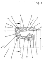
- the radial shaft seal shown in Figure 1 consists of the stiffening ring 1 made of a tough, hard plastic, which has an angular profile with a radially inwardly extending first leg 2 and an axially extending second leg 3. Both legs merge into one another educated.
- the first leg 2 is on the side facing away from the second leg 3 with evenly distributed on the circumference, open in the axial direction Provide recesses through which the continuation 6 of the ring seal and the lip seal pass, which necessitates a continuous formation of the material bodies on both sides.
- the ring seal 5, the extensions 6 and the sealing lip 4 thus consist of a merging material body made of rubber-elastic sealing material.
- This is relatively soft-elastic and is connected by direct molding and vulcanization to the material body forming the stiffening ring 1.
- the sealing lip 4 has the integrally molded dust lip 18 and a sealing edge 19, in the area of which an annular helical spring 20 made of metallic material is provided on its outside. This ensures uniform pressure of the sealing edge 19 against the shaft to be sealed, not shown, over long periods of time, which ensures the achievement of a sealing result that meets the highest demands.
- the stiffening ring 1 has the stop surface 9 and the support surface 7 at the opposite ends. Both have matching average diameters, which are connected in FIG. 1 by an imaginary cylinder surface 10.
- the outer peripheral surface 8 and the inner peripheral surface 11 of the second leg of the profile of the stiffening ring each have a positive distance from the cylinder surface 10, which gives the axially extending, second leg 3 of the stiffening ring 1 excellent buckling resistance.
- the radial shaft sealing ring according to the invention can thereby be mounted without problems, and a hard impact on the bottom of the receiving housing bore can also be accepted. With regard to the use of automatically working assembly tools, this results in a significant simplification.
- the support surface 7 has a radial distance from the outer circumferential surface 8 of the stiffening ring 1.
- the transition zone between the bottom of the receiving housing bore and its inner circumferential surface can thereby be made relatively generous.
- the stop surface 9 axially opposite the support surface 7 forms part of the tough and essentially uncompromising stiffening ring 1.
- the second leg 3 has a recess 12 radially outside of the first leg, in which the ring seal 5 is arranged.
- the recess is essentially delimited in the radial direction inwards by the surfaces 13, 14, which have a different spacing from the sealing axis 16 and which are designed to merge into one another in the circumferential direction.
- the surfaces 13, 14 and also the transition zones between the two are inclined at a flat angle to the sealing axis 16, as a result of which the ring seal 5, which is adapted in its profile, axially presses in one direction towards the right when the ring seal shown in FIG. 1 is pressed into the receiving housing bore on the left is able to evade slightly.
- the press-in process is simplified.
Landscapes
- Engineering & Computer Science (AREA)
- General Engineering & Computer Science (AREA)
- Mechanical Engineering (AREA)
- Sealing With Elastic Sealing Lips (AREA)
- Sealing Devices (AREA)
- Mechanical Sealing (AREA)
- Gasket Seals (AREA)
- Hybrid Cells (AREA)
- Materials For Medical Uses (AREA)
- Glass Compositions (AREA)
Priority Applications (1)
| Application Number | Priority Date | Filing Date | Title |
|---|---|---|---|
| AT87113886T ATE52839T1 (de) | 1987-06-25 | 1987-09-23 | Radialwellendichtring. |
Applications Claiming Priority (2)
| Application Number | Priority Date | Filing Date | Title |
|---|---|---|---|
| DE19873720930 DE3720930A1 (de) | 1987-06-25 | 1987-06-25 | Radialwellendichtring |
| DE3720930 | 1987-06-25 |
Publications (2)
| Publication Number | Publication Date |
|---|---|
| EP0297166A1 EP0297166A1 (de) | 1989-01-04 |
| EP0297166B1 true EP0297166B1 (de) | 1990-05-16 |
Family
ID=6330231
Family Applications (1)
| Application Number | Title | Priority Date | Filing Date |
|---|---|---|---|
| EP87113886A Expired - Lifetime EP0297166B1 (de) | 1987-06-25 | 1987-09-23 | Radialwellendichtring |
Country Status (9)
| Country | Link |
|---|---|
| US (1) | US4911454A (enExample) |
| EP (1) | EP0297166B1 (enExample) |
| JP (1) | JPH079266B2 (enExample) |
| AT (1) | ATE52839T1 (enExample) |
| BR (1) | BR8803123A (enExample) |
| CA (1) | CA1336609C (enExample) |
| DE (2) | DE3720930A1 (enExample) |
| ES (1) | ES2015933B3 (enExample) |
| MX (1) | MX169050B (enExample) |
Families Citing this family (13)
| Publication number | Priority date | Publication date | Assignee | Title |
|---|---|---|---|---|
| DE3927589C2 (de) * | 1989-08-22 | 1994-09-29 | Kaco Gmbh Co | Dichtungseinheit |
| JP2550548Y2 (ja) * | 1990-11-16 | 1997-10-15 | エヌオーケー 株式会社 | 密封装置 |
| US5269539A (en) * | 1992-04-13 | 1993-12-14 | Trw Inc. | Hydraulic shaft seal |
| DE9213374U1 (de) * | 1992-10-05 | 1994-02-10 | Martin Merkel GmbH & Co KG, 21107 Hamburg | Dichtring |
| US5380015A (en) * | 1993-12-17 | 1995-01-10 | Federal-Mogul Corporation | Machined shaft seal encased in an elastomeric sleeve |
| US5607168A (en) * | 1994-12-09 | 1997-03-04 | Albert Trostel Packings, Ltd. | Seal incorporating a resilient sealing element |
| DE102006059397B4 (de) * | 2006-12-08 | 2017-02-09 | Kaco Gmbh + Co. Kg | Dichtung |
| US8840115B2 (en) * | 2007-03-09 | 2014-09-23 | Freudenberg-Nok General Partnership | Wide range temperature and pressure hydraulic cylinder sealing system |
| DE102010028297B4 (de) * | 2010-04-28 | 2023-08-24 | Robert Bosch Gmbh | Lagerbuchsen-Anordnung für eine teleskopartige Lenkwelle und damit ausgestattetes Lenksystem |
| DE102014216672A1 (de) | 2014-08-21 | 2016-02-25 | Ford Global Technologies, Llc | Lagerbuchse sowie schwingungsdämpfende Verbindungsanordnung |
| DE102014216670B4 (de) | 2014-08-21 | 2016-05-19 | Ford Global Technologies, Llc | Lagerbuchse |
| DE202014103932U1 (de) | 2014-08-21 | 2014-09-19 | Ford Global Technologies, Llc | Lagerbuchse sowie schwingungsdämpfende Verbindungsanordnung |
| DE102016225551A1 (de) | 2016-12-20 | 2018-06-21 | Herbert Hänchen GmbH & Co. KG | Dichtring für eine dynamische Berührungsdichtung |
Family Cites Families (14)
| Publication number | Priority date | Publication date | Assignee | Title |
|---|---|---|---|---|
| US2249141A (en) * | 1936-04-14 | 1941-07-15 | Nat Oil Seal Co | Fluid seal |
| US2208482A (en) * | 1936-08-19 | 1940-07-16 | Victor Mfg & Gasket Co | Grease retainer with integral diaphragm and outer seal |
| DE832368C (de) * | 1941-08-23 | 1952-02-25 | Kupfer Asbest Co | Einbaufertige Wellendichtung |
| US2819106A (en) * | 1952-03-22 | 1958-01-07 | Voorhees Vanderveer | Oil seal |
| US3197217A (en) * | 1960-08-05 | 1965-07-27 | Johns Manville | Reinforced fluid seal |
| FR2234811A5 (en) * | 1973-06-20 | 1975-01-17 | Outillage Air Comprime | Sealing ring with T-section metal core - has rubber coating with corner lobes and exposed metal faces |
| US4132421A (en) * | 1975-02-14 | 1979-01-02 | Federal-Mogul Corporation | Shaft seal |
| DE2743501C3 (de) * | 1977-09-28 | 1981-01-08 | Fa. Carl Freudenberg, 6940 Weinheim | Dichtring |
| DE2807022C2 (de) * | 1978-02-18 | 1982-07-01 | Fa. Carl Freudenberg, 6940 Weinheim | Dichtring |
| JPS5933790B2 (ja) * | 1978-04-05 | 1984-08-17 | エヌオーケー株式会社 | オイルシ−ル |
| DE2934487C2 (de) * | 1979-08-25 | 1984-03-29 | Fa. Carl Freudenberg, 6940 Weinheim | Wellendichtring |
| DE3111726C1 (de) * | 1981-03-25 | 1982-09-30 | Goetze Ag, 5093 Burscheid | Dichtungsring |
| DE3403686A1 (de) * | 1984-02-03 | 1985-08-08 | Elring Dichtungswerke Gmbh, 7012 Fellbach | Radialwellendichtring |
| DE3405513C1 (de) * | 1984-02-16 | 1985-04-25 | Goetze Ag, 5093 Burscheid | Dichtung |
-
1987
- 1987-06-25 DE DE19873720930 patent/DE3720930A1/de active Granted
- 1987-09-23 DE DE8787113886T patent/DE3762769D1/de not_active Expired - Lifetime
- 1987-09-23 ES ES87113886T patent/ES2015933B3/es not_active Expired - Lifetime
- 1987-09-23 EP EP87113886A patent/EP0297166B1/de not_active Expired - Lifetime
- 1987-09-23 AT AT87113886T patent/ATE52839T1/de not_active IP Right Cessation
-
1988
- 1988-05-11 JP JP63114509A patent/JPH079266B2/ja not_active Expired - Lifetime
- 1988-06-10 MX MX011859A patent/MX169050B/es unknown
- 1988-06-14 CA CA000569456A patent/CA1336609C/en not_active Expired - Fee Related
- 1988-06-24 BR BR8803123A patent/BR8803123A/pt not_active IP Right Cessation
-
1989
- 1989-06-05 US US07/364,566 patent/US4911454A/en not_active Expired - Lifetime
Also Published As
| Publication number | Publication date |
|---|---|
| US4911454A (en) | 1990-03-27 |
| BR8803123A (pt) | 1989-01-24 |
| EP0297166A1 (de) | 1989-01-04 |
| CA1336609C (en) | 1995-08-08 |
| JPS6412178A (en) | 1989-01-17 |
| DE3720930C2 (enExample) | 1990-01-04 |
| ATE52839T1 (de) | 1990-06-15 |
| JPH079266B2 (ja) | 1995-02-01 |
| DE3720930A1 (de) | 1989-01-05 |
| MX169050B (es) | 1993-06-18 |
| DE3762769D1 (de) | 1990-06-21 |
| ES2015933B3 (es) | 1990-09-16 |
Similar Documents
| Publication | Publication Date | Title |
|---|---|---|
| EP0297166B1 (de) | Radialwellendichtring | |
| EP0563439B1 (de) | Dichtung für eine hin- und hergehende Stange | |
| EP0050213B1 (de) | Selbstausrichtende Lagerung | |
| DE3024089A1 (de) | Hydraulisch daempfendes einkammerlager | |
| DE102005029614B4 (de) | Buchsenlager mit radialem und/oder axialem Anschlag und Verfahren zur Erzeugung eines Axialanschlags bei einem Buchsenlager | |
| DE2949838C2 (de) | Wellendichtring | |
| DE10348372B4 (de) | Gleichlaufgelenkmanschette | |
| DE3244209C2 (de) | Dichtung zum Abdichten gegen hydraulische Medien, vorzugsweise Dichtabstreifelement | |
| EP0493731B1 (de) | Elastisches Lager | |
| DE3001998C2 (de) | Befestigungshülse für Maschinenteile | |
| DE2805711A1 (de) | Hydrostatische lagerstelle | |
| DE3024091C2 (de) | Hydraulisch dämpfendes Einkammerlager | |
| DE3016231C2 (de) | Dichtungsanordnung | |
| DE10113442C2 (de) | Lageranordnung für ein Wellenlager | |
| DE2609817A1 (de) | Kolben, insbesondere fuer einen pneumatikzylinder | |
| EP0052689B1 (de) | Stangen- oder Kolbendichtung | |
| DE3727355C2 (enExample) | ||
| DE69705341T2 (de) | Hydraulisches, schwingungsdämpfendes Lager und Kraftfahrzeug-Unterbaugruppe mit einem solchen Lager | |
| EP1384923B1 (de) | Dichtring zur Abdichtung eines Längenausgleichs einer Gelenkwelle | |
| EP0809038A2 (de) | Hydrolager | |
| DE8632410U1 (de) | Dichtungsgarnitur, insbesondere für Eisenbahnachsenlager | |
| DE20120029U1 (de) | Stutzen für eine Behälterwand | |
| DE2160645A1 (de) | Abstreifring für umlaufende Wellen u dgl | |
| DE3420523A1 (de) | Radialwellendichtring | |
| EP1818240A1 (de) | Druckstück für ein Lenkgetriebe |
Legal Events
| Date | Code | Title | Description |
|---|---|---|---|
| PUAI | Public reference made under article 153(3) epc to a published international application that has entered the european phase |
Free format text: ORIGINAL CODE: 0009012 |
|
| AK | Designated contracting states |
Kind code of ref document: A1 Designated state(s): AT BE CH DE ES FR GB IT LI NL SE |
|
| 17P | Request for examination filed |
Effective date: 19881111 |
|
| 17Q | First examination report despatched |
Effective date: 19891027 |
|
| GRAA | (expected) grant |
Free format text: ORIGINAL CODE: 0009210 |
|
| ITF | It: translation for a ep patent filed | ||
| AK | Designated contracting states |
Kind code of ref document: B1 Designated state(s): AT BE CH DE ES FR GB IT LI NL SE |
|
| REF | Corresponds to: |
Ref document number: 52839 Country of ref document: AT Date of ref document: 19900615 Kind code of ref document: T |
|
| ET | Fr: translation filed | ||
| REF | Corresponds to: |
Ref document number: 3762769 Country of ref document: DE Date of ref document: 19900621 |
|
| GBT | Gb: translation of ep patent filed (gb section 77(6)(a)/1977) | ||
| PLBE | No opposition filed within time limit |
Free format text: ORIGINAL CODE: 0009261 |
|
| STAA | Information on the status of an ep patent application or granted ep patent |
Free format text: STATUS: NO OPPOSITION FILED WITHIN TIME LIMIT |
|
| 26N | No opposition filed | ||
| ITTA | It: last paid annual fee | ||
| EAL | Se: european patent in force in sweden |
Ref document number: 87113886.3 |
|
| PGFP | Annual fee paid to national office [announced via postgrant information from national office to epo] |
Ref country code: DE Payment date: 19990902 Year of fee payment: 13 |
|
| PGFP | Annual fee paid to national office [announced via postgrant information from national office to epo] |
Ref country code: GB Payment date: 19990907 Year of fee payment: 13 |
|
| PGFP | Annual fee paid to national office [announced via postgrant information from national office to epo] |
Ref country code: ES Payment date: 19990914 Year of fee payment: 13 Ref country code: AT Payment date: 19990914 Year of fee payment: 13 |
|
| PGFP | Annual fee paid to national office [announced via postgrant information from national office to epo] |
Ref country code: FR Payment date: 19990917 Year of fee payment: 13 |
|
| PGFP | Annual fee paid to national office [announced via postgrant information from national office to epo] |
Ref country code: NL Payment date: 19990921 Year of fee payment: 13 |
|
| PGFP | Annual fee paid to national office [announced via postgrant information from national office to epo] |
Ref country code: BE Payment date: 19990922 Year of fee payment: 13 |
|
| PGFP | Annual fee paid to national office [announced via postgrant information from national office to epo] |
Ref country code: CH Payment date: 19990930 Year of fee payment: 13 |
|
| PGFP | Annual fee paid to national office [announced via postgrant information from national office to epo] |
Ref country code: SE Payment date: 20000921 Year of fee payment: 14 |
|
| PG25 | Lapsed in a contracting state [announced via postgrant information from national office to epo] |
Ref country code: GB Free format text: LAPSE BECAUSE OF NON-PAYMENT OF DUE FEES Effective date: 20000923 Ref country code: AT Free format text: LAPSE BECAUSE OF NON-PAYMENT OF DUE FEES Effective date: 20000923 |
|
| PG25 | Lapsed in a contracting state [announced via postgrant information from national office to epo] |
Ref country code: ES Free format text: LAPSE BECAUSE OF NON-PAYMENT OF DUE FEES Effective date: 20000924 |
|
| PG25 | Lapsed in a contracting state [announced via postgrant information from national office to epo] |
Ref country code: LI Free format text: LAPSE BECAUSE OF NON-PAYMENT OF DUE FEES Effective date: 20000930 Ref country code: CH Free format text: LAPSE BECAUSE OF NON-PAYMENT OF DUE FEES Effective date: 20000930 Ref country code: BE Free format text: LAPSE BECAUSE OF NON-PAYMENT OF DUE FEES Effective date: 20000930 |
|
| BERE | Be: lapsed |
Owner name: FIRMA CARL FREUDENBERG Effective date: 20000930 |
|
| PG25 | Lapsed in a contracting state [announced via postgrant information from national office to epo] |
Ref country code: NL Free format text: LAPSE BECAUSE OF NON-PAYMENT OF DUE FEES Effective date: 20010401 |
|
| REG | Reference to a national code |
Ref country code: CH Ref legal event code: PL |
|
| GBPC | Gb: european patent ceased through non-payment of renewal fee |
Effective date: 20000923 |
|
| PG25 | Lapsed in a contracting state [announced via postgrant information from national office to epo] |
Ref country code: FR Free format text: LAPSE BECAUSE OF NON-PAYMENT OF DUE FEES Effective date: 20010531 |
|
| NLV4 | Nl: lapsed or anulled due to non-payment of the annual fee |
Effective date: 20010401 |
|
| PG25 | Lapsed in a contracting state [announced via postgrant information from national office to epo] |
Ref country code: DE Free format text: LAPSE BECAUSE OF NON-PAYMENT OF DUE FEES Effective date: 20010601 |
|
| REG | Reference to a national code |
Ref country code: FR Ref legal event code: ST |
|
| PG25 | Lapsed in a contracting state [announced via postgrant information from national office to epo] |
Ref country code: SE Free format text: LAPSE BECAUSE OF NON-PAYMENT OF DUE FEES Effective date: 20010924 |
|
| EUG | Se: european patent has lapsed |
Ref document number: 87113886.3 |
|
| REG | Reference to a national code |
Ref country code: ES Ref legal event code: FD2A Effective date: 20011011 |
|
| PG25 | Lapsed in a contracting state [announced via postgrant information from national office to epo] |
Ref country code: IT Free format text: LAPSE BECAUSE OF NON-PAYMENT OF DUE FEES;WARNING: LAPSES OF ITALIAN PATENTS WITH EFFECTIVE DATE BEFORE 2007 MAY HAVE OCCURRED AT ANY TIME BEFORE 2007. THE CORRECT EFFECTIVE DATE MAY BE DIFFERENT FROM THE ONE RECORDED. Effective date: 20050923 |