EP0295140A2 - Fluorescent lamp with a predetermined cri and method for making - Google Patents
Fluorescent lamp with a predetermined cri and method for making Download PDFInfo
- Publication number
- EP0295140A2 EP0295140A2 EP88305353A EP88305353A EP0295140A2 EP 0295140 A2 EP0295140 A2 EP 0295140A2 EP 88305353 A EP88305353 A EP 88305353A EP 88305353 A EP88305353 A EP 88305353A EP 0295140 A2 EP0295140 A2 EP 0295140A2
- Authority
- EP
- European Patent Office
- Prior art keywords
- coating
- silica
- lamp
- phosphor
- cri
- Prior art date
- Legal status (The legal status is an assumption and is not a legal conclusion. Google has not performed a legal analysis and makes no representation as to the accuracy of the status listed.)
- Granted
Links
Images
Classifications
-
- H—ELECTRICITY
- H01—ELECTRIC ELEMENTS
- H01J—ELECTRIC DISCHARGE TUBES OR DISCHARGE LAMPS
- H01J61/00—Gas-discharge or vapour-discharge lamps
- H01J61/02—Details
- H01J61/30—Vessels; Containers
- H01J61/35—Vessels; Containers provided with coatings on the walls thereof; Selection of materials for the coatings
-
- H—ELECTRICITY
- H01—ELECTRIC ELEMENTS
- H01J—ELECTRIC DISCHARGE TUBES OR DISCHARGE LAMPS
- H01J61/00—Gas-discharge or vapour-discharge lamps
- H01J61/02—Details
- H01J61/38—Devices for influencing the colour or wavelength of the light
- H01J61/42—Devices for influencing the colour or wavelength of the light by transforming the wavelength of the light by luminescence
- H01J61/44—Devices characterised by the luminescent material
-
- H—ELECTRICITY
- H01—ELECTRIC ELEMENTS
- H01J—ELECTRIC DISCHARGE TUBES OR DISCHARGE LAMPS
- H01J61/00—Gas-discharge or vapour-discharge lamps
- H01J61/02—Details
- H01J61/38—Devices for influencing the colour or wavelength of the light
- H01J61/42—Devices for influencing the colour or wavelength of the light by transforming the wavelength of the light by luminescence
- H01J61/46—Devices characterised by the binder or other non-luminescent constituent of the luminescent material, e.g. for obtaining desired pouring or drying properties
-
- H—ELECTRICITY
- H01—ELECTRIC ELEMENTS
- H01J—ELECTRIC DISCHARGE TUBES OR DISCHARGE LAMPS
- H01J9/00—Apparatus or processes specially adapted for the manufacture, installation, removal, maintenance of electric discharge tubes, discharge lamps, or parts thereof; Recovery of material from discharge tubes or lamps
- H01J9/20—Manufacture of screens on or from which an image or pattern is formed, picked up, converted or stored; Applying coatings to the vessel
Definitions
- the present invention relates to lamps and more particularly to lamps including a phosphor layer and a non-phosphor layer.
- Non-luminescent particulate materials have been found to be useful when applied as an undercoating for the phosphor layer in mercury vapor discharge lamps, including fluorescent lamps.
- the phosphor coating is disposed on the inner surface of the lamp glass envelope in receptive proximity to the ultraviolet radiation being generated by the mercury discharge.
- non-luminescent particulate materials which have been used in fluorescent lamps such as, for example, aperture fluorescent reprographic lamps, include titanium dioxide, mixtures of titanium dioxide and up to 15 weight percent aluminum oxide, aluminum, and silver. Titanium dioxide is typically used in commercially available aperture fluorescent reprographic lamps.
- a layer of a non-luminescent particulate material is used to permit reduction in the phosphor coating weight.
- U.S. Patent No. 4,079,288 to Maloney et al. issued on 14 March 1978.
- U.S. Patent No. 4,074,288 discloses employing a reflector layer comprising vapor-formed spherical alumina particles having an individual particle size range from about 400 to 5000 Angstroms in diameter in fluorescent lamps to enable reduction in phosphor coating weight with minor lumen loss.
- the lamp data set forth in the patent shows an appreciable drop in lumen output at 100 hours.
- U.S. Patent No. 4,344,016 to Hoffman et al., issued on 10 August 1982 discloses a low pressure mercury vapor discharge lamp having an SiO2 coating having a thickness of 0.05 to 0.7 mg/cm2.
- U.S. Patent No. 4,344,016 expressly provides that the use of thicker coatings causes a reduction in the luminous efficacy due to the occurrence of an absorption of the visible light.
- a method for making a fluorescent lamp including a phosphor the lamp having a CRI approximately the same as the CRI of the phosphor, the method comprising applying a coating comprising fine particle-size silica at a coating weight greater than 0.7 milligrams per square centimeter to the inner surface of the lamp envelope to form a silica coated envelope; applying a coating of phosphor selected to provide a predetermined CRI over the silica layer; and processing the phosphor coated envelope into a finished lamp.
- a method for making a fluorescent lamp including a phosphor the lamp having a CRI approximately the same as the CRI of the phosphor, the method comprising applying a coating suspension comprising fine particle-size silica, water, a negative charge precursor, a defoaming agent, a surface active agent, an insolubilizing agent, a plasticizer, and two water-soluble binders to the inner surface of a lamp envelope to form a coated envelope; heating the coated envelope to cure the coating and remove the water from the coating; applying a phosphor suspension including a phosphor selected to provide a predetermined CRI over the cured silica layer; and processing the phosphor coated envelope into a finished lamp.
- a fluorescent lamp comprising a lamp envelope having an inner surface; a layer of fine particle-size silica disposed on the inner surface of the lamp envelope, the layer containing greater than about 0.7 mg/cm2 of fine particle-size silica; and a phosphor coating disposed over the silica layer, the phosphor coating comprising a phosphor selected to provide a predetermined CRI, the fluorescent lamp having a CRI approximately the same as the CRI of the phosphor.
- the present invention is directed to a fluorescent lamp including a phosphor, the lamp having a CRI approximately the same as the CRI of the phosphor, and a method for making a fluorescent lamp.
- the fluorescent lamp of the present invention includes a lamp envelope having an inner surface.
- a layer of fine particle-size silica is disposed on at least a portion of the inner surface of the lamp envelope at a coating weight greater than about 0.7 mg/cm2 and a phosphor coating is disposed over the silica layer.
- the phosphor coating may further be disposed on any portion of the inner surface of the envelope not coated with the fine particle-size silica layer.
- the Color Rendering Index (CRI) of fluorescent lamps having at least two phosphor layers, one of the phosphor layers being a less expensive phosphor layer used to permit a reduction in the weight of a more expensive phosphor can be improved by including a layer comprising fine particle-size silica (also referred to herein as silicon dioxide) in the lamp while eliminating the less expensive phosphor layer.
- a layer comprising fine particle-size silica also referred to herein as silicon dioxide
- the silica layer is interposed between the lamp envelope and the phosphor coating whereby no portion of the silica layer is exposed to or in contact with mercury in the lamp.
- Silica has an affinity for mercury and therefore will absorb mercury upon exposure thereto or contact therewith. The depletion of mercury in the lamp due to absorption of mercury by the silica layer can result in lamp maintenance loss.
- the use of the fine particle-size silica layer under the phosphor coating advantageously improves the performance of the phosphor in the lamp while causing negligible, if any, reduction in CRI of the desired phosphor.
- the CRI of a lamp including a fine particle-size silica layer and a coating of phosphor selected to provide a predetermined CRI is approximately the same as the CRI of a lamp including a coating of the same phosphor without the silica layer.
- the use of the silica layer further provides a lamp with a desired lumen output and CRI approximately equal to the CRI of the desired phosphor while using less phosphor than would be required to get the same lumen output if the desired phosphor were used alone.
- the present invention is particularly advantageous when used in a fluorescent lamp which includes a triphosphor layer.
- Fluorescent lamps containing a triphosphor layer often include a layer of a less expensive phosphor, for example, a halophosphate phosphor, interposed between the envelope and the triphosphor layer.
- the halophosphate layer is used to provide the desired lumen output for the lamp while permitting a reduction in the weight amount of the expensive triphosphor phosphor in the lamps.
- the inclusion of halophosphate layer does, however, result in a lower CRI for the lamp than if the triphosphor were used alone.
- the lamp When a layer of fine particle-size silica is substituted for the halophosphate phosphor in the above-described lamp, the lamp provides the desired lumen output with a reduced triphosphor weight without a reduction in CRI.
- an F40 fluorescent lamp including a single layer of a triphosphor blend requires a phosphor coating weight of about 5 grams (3.75 mg/cm2) to obtain a lamp with a commercially acceptable lumen output.
- a lamp in accordance with the present invention employing from about 1.7 to about 3.5 mg/cm2 fine particle-size SiO2 provides a comparable lumen output with approximately half as much of the same triphosphor blend.
- the silicon dioxide particles used to form the silica layer, or coating are high purity silicon dioxide, i.e., the silicon dioxide particles used comprise at least 99.0% by weight SiO2. Preferably, the silicon dioxide particles comprise greater than or equal to 99.8 by weight SiO2.
- the weight percent silicon dioxide represents the degree of purity of the silicon oxide used.
- the coating weight for the silicon dioxide layer is greater than 0.7 mg/cm2 and less than the weight at which the lumen output of the lamp is reduced due to absorption of the visible light by the silicon dioxide layer.
- a silicon dioxide layer coating weight of from about 0.7 to about 4 milligrams/square centimeter is acceptable.
- the coating weight of the silicon dioxide reflecting layer is from about 1.7 to about 3.5; and most preferably about 2.2 milligrams/square centimeter.
- fine particle-size silica or “fine particle-size silicon dioxide” refers to silica or silicon dioxide wherein at least about 80 weight percent of the silicon dioxide particles have a primary particle size from about 5 to about 100 nanometers.
- at least about 80 weight of the silica particles has a primary particle size from about 5 to about 100 nm and at least about 50 weight percent of those particles has a primary particle size from about 17 to about 80 nm.
- the primary particle size distribution peaks at about 40-50 nm.
- a fluorescent lamp in accordance with the present invention includes an envelope having a pair of electrodes sealed therein; a fill including an inert gas at a low pressure and a small quantity of mercury, a fine particle-size silica coating deposited on at least a portion of the inner surface of the lamp envelope; and a phosphor coating deposited over said silica layer.
- the phosphor may further be disposed on any uncoated portion of the inner surface of the lamp envelope.
- the phosphor coating may include more than one phosphor layer.
- the fluorescent lamp of the present invention may optionally include additional non-phosphor coatings for various other purposes.
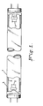
- the fluorescent lamp shown in FIGURE 1 comprises an elongated glass, e.g., soda lime silica glass, envelope 1 of circular cross-section. It has the usual electrodes 2 at each end of the envelope 1 supported on lead-in wires.
- the sealed envelope, or tube is filled with an inert gas, such as argon or a mixture of inert gases, such as argon and neon, at a low pressure, for example 2 torr; and a small quantity of mercury is added, at least enough to provide a low vapor pressure of, for example, about six (6) microns during operation.
- an inert gas such as argon or a mixture of inert gases, such as argon and neon
- the inner surface of the tubular glass envelope is first coated with a fine particle-size silicon dioxide coating 3.
- a layer 4 of the desired phosphor is coated over the silicon dioxide coating.
- the phosphor is a triphosphor blend.
- a triphosphor blend comprises a first luminescent material having an emission band with a maximum between 430 and 490 nm; a second luminescent material having its emission in the range of 520-565 nm; and a third luminescent material having its emission in the range 590-630 nm.
- Such blends are white-emitting and typically have color temperatures from about 2700 to about 4500K.
- the relative amounts of the components in the triphosphor blend is a function of the specific identify of the components used and the color desired. Such determinations are easily made by one of ordinary skill in the art.
- the present invention permits use of a phosphor coating having a weight less than that required to obtain an approximately equal lumen output in a fluorescent lamp including said phosphor coating and no silica layer with negligible, if any, CRI loss.
- This permits use of a triphosphor layer having a coating weight less than 3.75 mg/cm2.
- a preferred coating weight for the triphosphor blend is greater than or equal to 0.35 mg/cm2 and less than 3.75 mg/cm2.
- fluorescent lamp refers to any discharge device including a phosphor excited to fluorescence by ultra-violet radiation, regardless of configuration.
- a phosphor comprises any material excited to fluorescence by ultraviolet radiation.
- the silicon oxide layer of the present invention can be applied to the envelope by fully coating the lamp surface with an organic base-suspension of the above-described silicon dioxide particles
- the use of an organic-base suspension may produce poor texture coatings caused, for example, by flaking away of the coating. Flaking is more frequently experienced when applying thicker coatings, e.g., over 2.5 mg/cm2, from organic-base suspensions.
- the fine particle-size silica layer is applied to the envelope by fully coating the lamp surface with a water-base suspension of the above-described silicon dioxide particles.
- the water-base coating suspension further includes a negative charge precursor, two water-soluble binders, a defoaming agent, a surface active agent, an insolubilizing agent, and a film-plasticizing agent.
- the coating suspension is applied to the inner surface of the envelope and the coated envelope is then heated at a temperature and for a period of time sufficient to remove the water from the coating and to cure the coating.
- the phosphor coating is applied thereover by conventional lamp processing techniques.
- the cured silica layer is insoluble when contacted with an aqueous medium. This feature of the silica coating eliminates the need for a bake-out step prior to applying the phosphor coating suspension to the silica-coated envelope.
- the fine particle-size silica coating suspension is prepared by mixing a fine particle-size silica, such as Aerosil R OX-50 manufactured by DeGussa, Inc., with a mixture of deionized water, a negative charge precursor, for example, an aqueous base such as ammonium hydroxide, a defoaming agent, a surface active agent, an insolubilizing agent, and a plasticizer to form a slurry.
- a fine particle-size silica such as Aerosil R OX-50 manufactured by DeGussa, Inc.
- a negative charge precursor for example, an aqueous base such as ammonium hydroxide,a defoaming agent, a surface active agent, an insolubilizing agent, and a plasticizer
- Two water soluble binders are also added to the slurry.
- the two water soluble binders are added to the slurry in solution form.
- a preferred pair of water soluble binders for use in the present invention are a first binder comprising hydroxyethylcellulose and a second binder comprising poly(ethylene oxide).
- the hydroxyethylcellulose concentration is selected such that the cured film applied to the envelope is not soluble in the phosphor coating suspension applied thereover during the phosphor coating step.
- the concentration of hydroxyethylcellulose in the coating suspension is at least 1 weight percent based on the weight of the silica. Most preferably, the concentration is from about 1 to about 1.2 weight percent based on the weight of the silica. At higher concentrations, the solution can become too viscous requiring additional water to be added, thereby lowering the amount of fine particle-size silica which can be deposited on the inner surface of the lamp envelope.
- a single binder such as hydroxyethylcellulose
- a water-base coating suspension does not provide uniform distribution of silica on the inner surface of the lamp envelope.
- An acceptable film texture is characterized by tightly packed silica particles uniformly distributed on the inner surface of the lamp envelope so as to provide a smooth uninterrupted film.
- the further inclusion of a second water-soluble binder, such as, of poly (ethylene oxide) solution produces an acceptable film texture.
- concentration of the second water-soluble binder in the coating suspension is selected to produce a smooth film texture.
- poly (ethylene oxide) in the suspension in an amount of at least 8.8% based on the weight of the fine particle-size silica produces an acceptable film texture.
- a coating suspension containing 8.8% poly (ethylene oxide) based on the weight of fine particle-size silica deposits a layer containing about 3.0g fine particle-size silica layer on the inside of a 40T12 fluorescent tube (approximate surface area of about 1335 cm2).
- Thinner films of silica are obtained by diluting the silica coating suspension with additional amounts of a poly (ethylene oxide) solution with no effect on insolubility as long as 1.0% hydroxyethylcellulose based on the silica weight is present in the coating suspension.
- the weight ratio of the insolubilizing agent to the first binder in the coating suspension is at least 0.5. Preferably, the ratio is in the range of 0.5-1.0. At ratios below 0.5, the coating film does not attain film insolubility, i.e., the resultant film at least partially dissolves in the coating suspension when the phosphor is applied thereover.
- the insolubilizing agent is a material which effects cross-linking of the binders during a low-temperature (e.g., below 300°C) heating step which renders the silica coating insoluble.
- An example of a preferred insolubilizing agent is dimethylolurea.
- the plasticizer concentration based on the weight of the silica, is preferably about 2 to about 3% by weight. Below 2% by weight, pinholing can occur after the application of the phosphor coat; and above 3% by weight, coating defects, particularly mottling, can occur.
- An example of a preferred plasticizer is glycerine.
- the concentration of the negative charge precursor is preferably greater than or equal to about 0.05 moles per 100 grams (g) fine particle-size silica and most preferably greater than or equal to about 0.05 to about 0.091 moles per 100g of the silica.
- the introduction of negative ions reduces the thickening properties of the negatively charged fine particle-size silica.
- the coating suspension may be too viscous to coat bulbs.
- the negative charge precursor provides little additional lowering of the viscosity of the suspension.
- the viscosity of the fine particle size-silica coating suspension was lowered from 35-40 ⁇ viscosity (viscosity without the ammonium hydroxide) to 16-20 ⁇ viscosity (with ammonium hydroxide) measured by the Sylvania Cup.
- the viscosity number given herein was measured as the number of seconds required to empty a special cup, referred to herein as the Sylvania Cup, filled with the material being measured, and having a one-eighth inch diameter hole at the center of its bottom, through which the material may flow.
- the cup is made from a nickel crucible having an inside diameter, at its top, of 1.5 inches (3.81 cm). Such a crucible has a flat bottom, which has been rounded out for the present purpose so that the overall inside length from the top of the cup to the bottom is 1 1/2 inches (3.81 cm).
- the cup holds 33 cc of liquid when filled to the top.
- the defoaming agent and surfactant can be any such materials conventionally employed in lamp coating technology. Such materials are well known in the art.
- At least about 0.01% defoaming agent based upon the volume of the coating suspension is used and most preferably from about 0.025% to about 0.04%.
- the concentration of the surfactant in the coating suspension is preferably at least about 0.001% based upon the volume of suspension and most preferably from about 0.0025% to about 0.004%.
- the concentration of the fine particle-size silica in the coating suspension is preferably no more than about 150 g/l and most preferably from about 40 g/l to about 132 g/l. At concentrations less than 40 g/l an insufficient amount of silica may be deposited in the lamp; and at concentrations above 150 g/l non uniform films may occur.
- a coating suspension in accordance with the Present invention was prepared from the following components mixed together in the order as listed: 150cc deionized water 12cc ammonium hydroxide Reagent Grade Assay (28-31%) 0.28cc defoaming agent (Hercules type 831) 0.028cc surfactant (BASF type 25R-1 Pluronic) 2.5cc glycerine 0.45g dimethylolurea 150g Aerosil R OX-50 (obtained from DeGussa, Inc.) 100cc hydroxyethylcellulose solution containing 1.7 weight percent of the resin (Natrosol (HEC) grade 250 MBR obtained from Hercules) in water 600cc poly (ethylene oxide) solution containing 2.2 weight percent of the resin (WSRN 2000 obtained from Union Carbide) in water
- An insoluble fine particle-size silica layer was applied by causing the above-formulated coating suspension to flow down the inner wall of a tubular fluorescent lamp envelope being held in a vertical position.
- the coated tubes were placed in an air drying chamber maintained at a temperature of 230°F(110°C) for 30 minutes to remove the water and complete the cross linking reaction between the two water-soluble binders (also referred to herein as resins) and the cross-linking reactant, dimethylolurea.
- Example formulation allowed about 2.5-3.0 grams of Aerosil R OX-50 to be deposited on the inner surface of a standard 40 watt T12 fluorescent lamp envelope of circular cross-section.
- the dried silica coated bulb was allowed to cool to room temperature, following which the silica layer was overcoated with water-base 3K° Royal White triphosphor suspension by known techniques.
- the double coated bulb was baked at about 600°C for 2 minutes to remove the organic components of the binders.
- the coated envelope was then processed into a fluorescent lamp by conventional lamp manufacturing techniques.
- the present invention advantageously eliminates the need for more than one bakeout step in lamp processing.
- Lamp A is a Sylvania Standard 3K° Royal White 40T12 fluorescent lamp.
- the lamp includes two phosphor layers.
- the first coat applied to the envelope is a warm white halophosphate phosphor and the second coat is a 3K° triphosphor blend, the composition of which is described below.
- Lamp B is a 40T12 fluorescent lamp in accordance with the present invention.
- the first coat is a fine particle-size silica layer which was applied by a method similar to that described in the foregoing Example.
- the second coat is the standard 3K° triphosphor blend described below.
- the lamps were otherwise fabricated using conventional lamp processing techniques.
- the weights of the coatings, or layers, in the lamp are set forth in Table I as well as lamp performance data for 10,000 hours, the x-y color coordinates and the CRI for the lamps.
- the standard 3K° blend formulation used in the initial evaluation contained: 65.0% Y2O3:Eu red phosphor 33.5% Ce, Tb Magnesium Aluminate green phosphor 1.5% Ba, Mg Aluminate:Eu blue phosphor
- the initial evaluation showed (at 100 hours) the 3K° Royal White lamps including the single phosphor layer with the silica layer provided a 5 unit improvement in CRI over the standard 3K° Royal White lamps. After 10,000 hours burning, the 3K° Royal White lamps including the silica layer were 1.5% brighter than the standard lamps due to the 2% superior maintenance characteristics. The color of the lamps, including the silica layers, however, were slightly redder.
- the corrected 3K° blend formulation for lamps including a fine particle-size silica layer is as follows: 64.0% Y2O3:Eu red phosphor 34.0% Ce, Tb Magnesium Aluminate green phosphor 2.0% Ba, Mg Aluminate:Eu blue phosphor
- a triphosphor blend containing one percent less red phosphor, 0.5% more green phosphor, and 0.5% more blue than the standard blend is necessary to obtain the standard 3K° color for a fluorescent lamp including a layer of fine particle-size silica interposed between the lamp envelope and the phosphor layer.
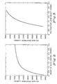
- a second lamp test series was also conducted to compare the results of lamps containing different weights of fine particle-size silica in the silica layer. Aerosil R OX-50 was used as the fine particle-size silica in this test series. The weight of the fine particle-size silica layer was varied over a range from 0.98-3.38g in 40T12 fluorescent lamps. The silica layer in each lamp was applied by a method similar to the method of the foregoing Example with the amount of poly (ethylene oxide) being increased to apply the lighter silica coating weights. Each lamp of the test series was second coated with approximately the same amount of the standard 3K° triphosphor blend formulation. The coating weights, brightness, color, and CRI results for this second lamp test series are tabulated in Table 2.
- a third lamp test series involved a second-coat 3K° triphosphor weight series.
- the 3K° triphosphor coating weight was varied of a range from 0.91g to 2.37g.
- the corrected 3K° triphosphor blend formulation was the 3K° triphosphor used in the third lamp series.
- the fine particle-size silica layer of each lamp had a weight approximately 2 grams. Aerosil R OX-50 was used as the fine particle-size silica in the lamps of this third lamp test series.
- the results of this lamp series are tabulated in Table 3.
- lower brightness (lower lumens) was obtained at lower triphosphor weights.
- a 61.6% reduction in triphosphor weight, from 2.37g to 0.91g results in a 22.7% reduction in brightness.
- the 100 hour lumen data for the lamps described in Table 3 is graphically represented in FIGURE 3.
- silica coating in these tests clearly show that an 83.0-84.0 CRI 2900°K lamp is obtained using a fine particle-size silica first coat and 3K° triphosphor second coat.
- Aerosil R OX-50 obtained from DeGussa, Inc. Aerosil R OX-50 is a fluffy white powder and has a BET surface area of 50 ⁇ 15 m2/g. The average primary particle size of OX-50 is 40 nm. Aerosil R OX-50 contains greater than 99.8 percent SiO2, less than 0.08 % Al2O3, less than 0.01% Fe2O3, less than 0.03 TiO2, less than 0.01% HCl, and less than 0.1% sieve residue. (OX-50 has a tamped density of approximately 130 g/l).
Abstract
Description
- The present invention relates to lamps and more particularly to lamps including a phosphor layer and a non-phosphor layer.
- Various coatings of non-luminescent particulate materials have been found to be useful when applied as an undercoating for the phosphor layer in mercury vapor discharge lamps, including fluorescent lamps. The phosphor coating is disposed on the inner surface of the lamp glass envelope in receptive proximity to the ultraviolet radiation being generated by the mercury discharge.
- Examples of non-luminescent particulate materials which have been used in fluorescent lamps such as, for example, aperture fluorescent reprographic lamps, include titanium dioxide, mixtures of titanium dioxide and up to 15 weight percent aluminum oxide, aluminum, and silver. Titanium dioxide is typically used in commercially available aperture fluorescent reprographic lamps.
- In some instances a layer of a non-luminescent particulate material is used to permit reduction in the phosphor coating weight. See, for example, U.S. Patent No. 4,079,288 to Maloney et al., issued on 14 March 1978. U.S. Patent No. 4,074,288 discloses employing a reflector layer comprising vapor-formed spherical alumina particles having an individual particle size range from about 400 to 5000 Angstroms in diameter in fluorescent lamps to enable reduction in phosphor coating weight with minor lumen loss. The lamp data set forth in the patent, however, shows an appreciable drop in lumen output at 100 hours.
- U.S. Patent No. 4,344,016 to Hoffman et al., issued on 10 August 1982 discloses a low pressure mercury vapor discharge lamp having an SiO₂ coating having a thickness of 0.05 to 0.7 mg/cm². U.S. Patent No. 4,344,016 expressly provides that the use of thicker coatings causes a reduction in the luminous efficacy due to the occurrence of an absorption of the visible light.
- Other attempts to improve the performance of and/or to reduce the costs associated with the manufacture of mercury vapor discharge lamps have involved the use of more than one phosphor layer. While the inclusion of an additional phosphor layer may achieve the desired maintenance improvement or cost reduction, the use of an additional phosphor coating is typically accompanied by a decrease in Color Rendering Index (CRI) of the lamp including the additional layer of phosphor.
- In accordance with the present invention there is provided a method for making a fluorescent lamp including a phosphor, the lamp having a CRI approximately the same as the CRI of the phosphor, the method comprising applying a coating comprising fine particle-size silica at a coating weight greater than 0.7 milligrams per square centimeter to the inner surface of the lamp envelope to form a silica coated envelope; applying a coating of phosphor selected to provide a predetermined CRI over the silica layer; and processing the phosphor coated envelope into a finished lamp.
- In accordance with another aspect of the present invention there is provided a method for making a fluorescent lamp including a phosphor, the lamp having a CRI approximately the same as the CRI of the phosphor, the method comprising applying a coating suspension comprising fine particle-size silica, water, a negative charge precursor, a defoaming agent, a surface active agent, an insolubilizing agent, a plasticizer, and two water-soluble binders to the inner surface of a lamp envelope to form a coated envelope; heating the coated envelope to cure the coating and remove the water from the coating; applying a phosphor suspension including a phosphor selected to provide a predetermined CRI over the cured silica layer; and processing the phosphor coated envelope into a finished lamp.
- In accordance with another aspect of the present invention, there is provided a fluorescent lamp comprising a lamp envelope having an inner surface; a layer of fine particle-size silica disposed on the inner surface of the lamp envelope, the layer containing greater than about 0.7 mg/cm² of fine particle-size silica; and a phosphor coating disposed over the silica layer, the phosphor coating comprising a phosphor selected to provide a predetermined CRI, the fluorescent lamp having a CRI approximately the same as the CRI of the phosphor.
- The invention is illustrated by way of example in the accompanying drawings in which:
- FIGURE 1 is an elevational view of a fluorescent lamp, in partial cross-section, in accordance with the present invention.
- FIGURE 2 graphically represents lumen output as a function of the weight of the silica coating after 100 hours of operation for an F40 lamp in accordance with the present invention which includes a phosphor coating with a weight of about 1.7 grams.
- FIGURE 3 graphically represents lumen output as a function of the triphosphor layer weight after 100 hours of operation for a lamp in accordance with the present invention which includes a fine particle-size silica layer with a weight of about 2 grams.
- For a better understanding of the present invention, together with other and further objects, advantages, and capabilities thereof, reference is made to the following disclosure and appended claims in connection with the above-described drawings.
- The present invention is directed to a fluorescent lamp including a phosphor, the lamp having a CRI approximately the same as the CRI of the phosphor, and a method for making a fluorescent lamp.
- The fluorescent lamp of the present invention includes a lamp envelope having an inner surface. A layer of fine particle-size silica is disposed on at least a portion of the inner surface of the lamp envelope at a coating weight greater than about 0.7 mg/cm² and a phosphor coating is disposed over the silica layer. The phosphor coating may further be disposed on any portion of the inner surface of the envelope not coated with the fine particle-size silica layer.
- In accordance with a preferred embodiment of the present invention it has been found that the Color Rendering Index (CRI) of fluorescent lamps having at least two phosphor layers, one of the phosphor layers being a less expensive phosphor layer used to permit a reduction in the weight of a more expensive phosphor, can be improved by including a layer comprising fine particle-size silica (also referred to herein as silicon dioxide) in the lamp while eliminating the less expensive phosphor layer. Most preferably the silica layer is interposed between the lamp envelope and the phosphor coating whereby no portion of the silica layer is exposed to or in contact with mercury in the lamp. Silica has an affinity for mercury and therefore will absorb mercury upon exposure thereto or contact therewith. The depletion of mercury in the lamp due to absorption of mercury by the silica layer can result in lamp maintenance loss.
- The use of the fine particle-size silica layer under the phosphor coating advantageously improves the performance of the phosphor in the lamp while causing negligible, if any, reduction in CRI of the desired phosphor. In other words, the CRI of a lamp including a fine particle-size silica layer and a coating of phosphor selected to provide a predetermined CRI is approximately the same as the CRI of a lamp including a coating of the same phosphor without the silica layer. The use of the silica layer further provides a lamp with a desired lumen output and CRI approximately equal to the CRI of the desired phosphor while using less phosphor than would be required to get the same lumen output if the desired phosphor were used alone.
- The present invention is particularly advantageous when used in a fluorescent lamp which includes a triphosphor layer. Fluorescent lamps containing a triphosphor layer often include a layer of a less expensive phosphor, for example, a halophosphate phosphor, interposed between the envelope and the triphosphor layer. The halophosphate layer is used to provide the desired lumen output for the lamp while permitting a reduction in the weight amount of the expensive triphosphor phosphor in the lamps. The inclusion of halophosphate layer does, however, result in a lower CRI for the lamp than if the triphosphor were used alone.
- When a layer of fine particle-size silica is substituted for the halophosphate phosphor in the above-described lamp, the lamp provides the desired lumen output with a reduced triphosphor weight without a reduction in CRI.
- For example, an F40 fluorescent lamp including a single layer of a triphosphor blend (with red phosphor Type No. 2342 obtained from the Chemical and Metallurgical Division of GTE Products Corporation, Towanda, Pennsylvania) requires a phosphor coating weight of about 5 grams (3.75 mg/cm²) to obtain a lamp with a commercially acceptable lumen output. A lamp in accordance with the present invention employing from about 1.7 to about 3.5 mg/cm² fine particle-size SiO₂ provides a comparable lumen output with approximately half as much of the same triphosphor blend.
- The silicon dioxide particles used to form the silica layer, or coating, are high purity silicon dioxide, i.e., the silicon dioxide particles used comprise at least 99.0% by weight SiO₂. Preferably, the silicon dioxide particles comprise greater than or equal to 99.8 by weight SiO₂. The weight percent silicon dioxide represents the degree of purity of the silicon oxide used.
- The coating weight for the silicon dioxide layer is greater than 0.7 mg/cm² and less than the weight at which the lumen output of the lamp is reduced due to absorption of the visible light by the silicon dioxide layer. For example, a silicon dioxide layer coating weight of from about 0.7 to about 4 milligrams/square centimeter is acceptable. Preferably, the coating weight of the silicon dioxide reflecting layer is from about 1.7 to about 3.5; and most preferably about 2.2 milligrams/square centimeter.
- As used herein, "fine particle-size silica" or "fine particle-size silicon dioxide" refers to silica or silicon dioxide wherein at least about 80 weight percent of the silicon dioxide particles have a primary particle size from about 5 to about 100 nanometers. Preferably, at least about 80 weight of the silica particles has a primary particle size from about 5 to about 100 nm and at least about 50 weight percent of those particles has a primary particle size from about 17 to about 80 nm. Most preferably, the primary particle size distribution peaks at about 40-50 nm.
- A fluorescent lamp in accordance with the present invention includes an envelope having a pair of electrodes sealed therein; a fill including an inert gas at a low pressure and a small quantity of mercury, a fine particle-size silica coating deposited on at least a portion of the inner surface of the lamp envelope; and a phosphor coating deposited over said silica layer. The phosphor may further be disposed on any uncoated portion of the inner surface of the lamp envelope. The phosphor coating may include more than one phosphor layer.
- The fluorescent lamp of the present invention may optionally include additional non-phosphor coatings for various other purposes.
- Referring to FIGURE 1, there is shown an example of a fluorescent lamp in accordance with the present invention. The fluorescent lamp shown in FIGURE 1 comprises an elongated glass, e.g., soda lime silica glass, envelope 1 of circular cross-section. It has the
usual electrodes 2 at each end of the envelope 1 supported on lead-in wires. The sealed envelope, or tube, is filled with an inert gas, such as argon or a mixture of inert gases, such as argon and neon, at a low pressure, for example 2 torr; and a small quantity of mercury is added, at least enough to provide a low vapor pressure of, for example, about six (6) microns during operation. - The inner surface of the tubular glass envelope is first coated with a fine particle-size
silicon dioxide coating 3. A layer 4 of the desired phosphor is coated over the silicon dioxide coating. - In a preferred embodiment of the present invention the phosphor is a triphosphor blend. A triphosphor blend comprises a first luminescent material having an emission band with a maximum between 430 and 490 nm; a second luminescent material having its emission in the range of 520-565 nm; and a third luminescent material having its emission in the range 590-630 nm. Such blends are white-emitting and typically have color temperatures from about 2700 to about 4500K. The relative amounts of the components in the triphosphor blend is a function of the specific identify of the components used and the color desired. Such determinations are easily made by one of ordinary skill in the art.
- As described above, the present invention permits use of a phosphor coating having a weight less than that required to obtain an approximately equal lumen output in a fluorescent lamp including said phosphor coating and no silica layer with negligible, if any, CRI loss. This permits use of a triphosphor layer having a coating weight less than 3.75 mg/cm². A preferred coating weight for the triphosphor blend is greater than or equal to 0.35 mg/cm² and less than 3.75 mg/cm².
- As used herein, "fluorescent lamp" refers to any discharge device including a phosphor excited to fluorescence by ultra-violet radiation, regardless of configuration.
- A phosphor comprises any material excited to fluorescence by ultraviolet radiation.
- While the silicon oxide layer of the present invention can be applied to the envelope by fully coating the lamp surface with an organic base-suspension of the above-described silicon dioxide particles, the use of an organic-base suspension may produce poor texture coatings caused, for example, by flaking away of the coating. Flaking is more frequently experienced when applying thicker coatings, e.g., over 2.5 mg/cm², from organic-base suspensions.
- Advantageously, such flaking is eliminated when the fine particle-size silica layer is applied to the envelope by fully coating the lamp surface with a water-base suspension of the above-described silicon dioxide particles. In addition to the fine particle-size silica, the water-base coating suspension further includes a negative charge precursor, two water-soluble binders, a defoaming agent, a surface active agent, an insolubilizing agent, and a film-plasticizing agent. The coating suspension is applied to the inner surface of the envelope and the coated envelope is then heated at a temperature and for a period of time sufficient to remove the water from the coating and to cure the coating. The phosphor coating is applied thereover by conventional lamp processing techniques.
- Advantageously, the cured silica layer is insoluble when contacted with an aqueous medium. This feature of the silica coating eliminates the need for a bake-out step prior to applying the phosphor coating suspension to the silica-coated envelope.
- More particularly, the fine particle-size silica coating suspension is prepared by mixing a fine particle-size silica, such as AerosilR OX-50 manufactured by DeGussa, Inc., with a mixture of deionized water, a negative charge precursor, for example, an aqueous base such as ammonium hydroxide,a defoaming agent, a surface active agent, an insolubilizing agent, and a plasticizer to form a slurry. Two water soluble binders are also added to the slurry. Preferably the two water soluble binders are added to the slurry in solution form.
- A preferred pair of water soluble binders for use in the present invention are a first binder comprising hydroxyethylcellulose and a second binder comprising poly(ethylene oxide). When this preferred pair of binders is used, the hydroxyethylcellulose concentration is selected such that the cured film applied to the envelope is not soluble in the phosphor coating suspension applied thereover during the phosphor coating step. Preferably, the concentration of hydroxyethylcellulose in the coating suspension is at least 1 weight percent based on the weight of the silica. Most preferably, the concentration is from about 1 to about 1.2 weight percent based on the weight of the silica. At higher concentrations, the solution can become too viscous requiring additional water to be added, thereby lowering the amount of fine particle-size silica which can be deposited on the inner surface of the lamp envelope.
- The use of a single binder, such as hydroxyethylcellulose, in a water-base coating suspension, does not provide uniform distribution of silica on the inner surface of the lamp envelope. An acceptable film texture is characterized by tightly packed silica particles uniformly distributed on the inner surface of the lamp envelope so as to provide a smooth uninterrupted film.
- Advantageously, the further inclusion of a second water-soluble binder, such as, of poly (ethylene oxide) solution produces an acceptable film texture. The concentration of the second water-soluble binder in the coating suspension is selected to produce a smooth film texture. For example, the inclusion of poly (ethylene oxide) in the suspension in an amount of at least 8.8% based on the weight of the fine particle-size silica produces an acceptable film texture. A coating suspension containing 8.8% poly (ethylene oxide) based on the weight of fine particle-size silica deposits a layer containing about 3.0g fine particle-size silica layer on the inside of a 40T12 fluorescent tube (approximate surface area of about 1335 cm²). Thinner films of silica are obtained by diluting the silica coating suspension with additional amounts of a poly (ethylene oxide) solution with no effect on insolubility as long as 1.0% hydroxyethylcellulose based on the silica weight is present in the coating suspension.
- The weight ratio of the insolubilizing agent to the first binder in the coating suspension is at least 0.5. Preferably, the ratio is in the range of 0.5-1.0. At ratios below 0.5, the coating film does not attain film insolubility, i.e., the resultant film at least partially dissolves in the coating suspension when the phosphor is applied thereover. The insolubilizing agent is a material which effects cross-linking of the binders during a low-temperature (e.g., below 300°C) heating step which renders the silica coating insoluble. An example of a preferred insolubilizing agent is dimethylolurea.
- The plasticizer concentration, based on the weight of the silica, is preferably about 2 to about 3% by weight. Below 2% by weight, pinholing can occur after the application of the phosphor coat; and above 3% by weight, coating defects, particularly mottling, can occur. An example of a preferred plasticizer is glycerine.
- The concentration of the negative charge precursor is preferably greater than or equal to about 0.05 moles per 100 grams (g) fine particle-size silica and most preferably greater than or equal to about 0.05 to about 0.091 moles per 100g of the silica. The introduction of negative ions reduces the thickening properties of the negatively charged fine particle-size silica. In amounts below 0.05 moles per 100g silica, the coating suspension may be too viscous to coat bulbs. In amounts in excess of 0.091 moles per 100g silica, the negative charge precursor provides little additional lowering of the viscosity of the suspension. For example, when an aqueous base such as NH₄OH is used as the negative charge precursor in an amount of about 0.05 to about 0.091 moles of NH₄OH per 100g silica, the viscosity of the fine particle size-silica coating suspension was lowered from 35-40˝ viscosity (viscosity without the ammonium hydroxide) to 16-20˝ viscosity (with ammonium hydroxide) measured by the Sylvania Cup.
- The viscosity number given herein was measured as the number of seconds required to empty a special cup, referred to herein as the Sylvania Cup, filled with the material being measured, and having a one-eighth inch diameter hole at the center of its bottom, through which the material may flow. The cup is made from a nickel crucible having an inside diameter, at its top, of 1.5 inches (3.81 cm). Such a crucible has a flat bottom, which has been rounded out for the present purpose so that the overall inside length from the top of the cup to the bottom is 1 1/2 inches (3.81 cm). The cup holds 33 cc of liquid when filled to the top.
- The defoaming agent and surfactant (also referred to herein as a "surface active agent) can be any such materials conventionally employed in lamp coating technology. Such materials are well known in the art.
- Preferably at least about 0.01% defoaming agent based upon the volume of the coating suspension is used and most preferably from about 0.025% to about 0.04%. The concentration of the surfactant in the coating suspension is preferably at least about 0.001% based upon the volume of suspension and most preferably from about 0.0025% to about 0.004%.
- The concentration of the fine particle-size silica in the coating suspension is preferably no more than about 150 g/l and most preferably from about 40 g/l to about 132 g/l. At concentrations less than 40 g/l an insufficient amount of silica may be deposited in the lamp; and at concentrations above 150 g/l non uniform films may occur.
- The following is exemplary of the making of a lamp in accordance with the present invention and is not to be construed as necessarily limiting thereof.
- A coating suspension in accordance with the Present invention was prepared from the following components mixed together in the order as listed:
150cc deionized water
12cc ammonium hydroxide Reagent Grade Assay (28-31%)
0.28cc defoaming agent (Hercules type 831)
0.028cc surfactant (BASF type 25R-1 Pluronic)
2.5cc glycerine
0.45g dimethylolurea
150g AerosilR OX-50 (obtained from DeGussa, Inc.)
100cc hydroxyethylcellulose solution containing 1.7 weight percent of the resin (Natrosol (HEC) grade 250 MBR obtained from Hercules) in water
600cc poly (ethylene oxide) solution containing 2.2 weight percent of the resin (WSRN 2000 obtained from Union Carbide) in water - An insoluble fine particle-size silica layer was applied by causing the above-formulated coating suspension to flow down the inner wall of a tubular fluorescent lamp envelope being held in a vertical position.
- After allowing the bulb to drain for 30 seconds, the coated tubes were placed in an air drying chamber maintained at a temperature of 230°F(110°C) for 30 minutes to remove the water and complete the cross linking reaction between the two water-soluble binders (also referred to herein as resins) and the cross-linking reactant, dimethylolurea.
- The preceding Example formulation allowed about 2.5-3.0 grams of AerosilR OX-50 to be deposited on the inner surface of a standard 40 watt T12 fluorescent lamp envelope of circular cross-section. The dried silica coated bulb was allowed to cool to room temperature, following which the silica layer was overcoated with water-base 3K° Royal White triphosphor suspension by known techniques. The double coated bulb was baked at about 600°C for 2 minutes to remove the organic components of the binders. The coated envelope was then processed into a fluorescent lamp by conventional lamp manufacturing techniques. The present invention advantageously eliminates the need for more than one bakeout step in lamp processing.
- An initial lamp test was conducted to compare the performance of a lamp employing a double phosphor coating with a lamp in accordance with the present invention.
- The initial lamp test results are tabulated in Table 1. Lamp A is a Sylvania Standard 3K° Royal White 40T12 fluorescent lamp. The lamp includes two phosphor layers. The first coat applied to the envelope is a warm white halophosphate phosphor and the second coat is a 3K° triphosphor blend, the composition of which is described below. Lamp B is a 40T12 fluorescent lamp in accordance with the present invention. The first coat is a fine particle-size silica layer which was applied by a method similar to that described in the foregoing Example. The second coat is the standard 3K° triphosphor blend described below. The lamps were otherwise fabricated using conventional lamp processing techniques. The weights of the coatings, or layers, in the lamp are set forth in Table I as well as lamp performance data for 10,000 hours, the x-y color coordinates and the CRI for the lamps.
- The standard 3K° blend formulation used in the initial evaluation contained:
65.0% Y₂O₃:Eu red phosphor
33.5% Ce, Tb Magnesium Aluminate green phosphor
1.5% Ba, Mg Aluminate:Eu blue phosphor - The initial evaluation showed (at 100 hours) the 3K° Royal White lamps including the single phosphor layer with the silica layer provided a 5 unit improvement in CRI over the standard 3K° Royal White lamps. After 10,000 hours burning, the 3K° Royal White lamps including the silica layer were 1.5% brighter than the standard lamps due to the 2% superior maintenance characteristics. The color of the lamps, including the silica layers, however, were slightly redder.
- The necessary color corrections were determined. The corrected 3K° blend formulation for lamps including a fine particle-size silica layer is as follows:
64.0% Y₂O₃:Eu red phosphor
34.0% Ce, Tb Magnesium Aluminate green phosphor
2.0% Ba, Mg Aluminate:Eu blue phosphor
- A triphosphor blend containing one percent less red phosphor, 0.5% more green phosphor, and 0.5% more blue than the standard blend is necessary to obtain the standard 3K° color for a fluorescent lamp including a layer of fine particle-size silica interposed between the lamp envelope and the phosphor layer.
- A second lamp test series was also conducted to compare the results of lamps containing different weights of fine particle-size silica in the silica layer. AerosilR OX-50 was used as the fine particle-size silica in this test series. The weight of the fine particle-size silica layer was varied over a range from 0.98-3.38g in 40T12 fluorescent lamps. The silica layer in each lamp was applied by a method similar to the method of the foregoing Example with the amount of poly (ethylene oxide) being increased to apply the lighter silica coating weights. Each lamp of the test series was second coated with approximately the same amount of the standard 3K° triphosphor blend formulation. The coating weights, brightness, color, and CRI results for this second lamp test series are tabulated in Table 2. A small decrease in brightness occurs as the silica layer weight decreases. A 71% reduction in silica layer weight, from 3.38g to 0.98g, results in a brightness loss of 4.5%. Equivalent brightness to the standard 3K° lamp is achieved at the highest silica layer weight of 3.38g. It should be noted, however, that the CRI of all the silica containing lamps remains essentially the same, approximately 84.0, regardless of the OX-50 weight. The 100 hour lumen data for the lamps described in Table 2 is graphically represented in FIGURE 2.
- A third lamp test series involved a second-coat 3K° triphosphor weight series. The 3K° triphosphor coating weight was varied of a range from 0.91g to 2.37g. (The corrected 3K° triphosphor blend formulation was the 3K° triphosphor used in the third lamp series.) The fine particle-size silica layer of each lamp had a weight approximately 2 grams. AerosilR OX-50 was used as the fine particle-size silica in the lamps of this third lamp test series. The results of this lamp series are tabulated in Table 3. As expected, lower brightness (lower lumens) was obtained at lower triphosphor weights. A 61.6% reduction in triphosphor weight, from 2.37g to 0.91g, results in a 22.7% reduction in brightness. However, high CRI's, around 84.0, were obtained, regardless of the triphosphor weight. The 100 hour lumen data for the lamps described in Table 3 is graphically represented in FIGURE 3.
- The silica coating in these tests clearly show that an 83.0-84.0
CRI 2900°K lamp is obtained using a fine particle-size silica first coat and 3K° triphosphor second coat. - The silica used in the above-described experiments and tests was AerosilR OX-50 obtained from DeGussa, Inc. AerosilR OX-50 is a fluffy white powder and has a BET surface area of 50 ± 15 m²/g. The average primary particle size of OX-50 is 40 nm. AerosilR OX-50 contains greater than 99.8 percent SiO₂, less than 0.08 % Al₂O₃, less than 0.01% Fe₂O₃, less than 0.03 TiO₂, less than 0.01% HCl, and less than 0.1% sieve residue. (OX-50 has a tamped density of approximately 130 g/l).


- While the foregoing lamp tests illustrate the advantages of the present invention when the fine particle-size silica layer comprises silicon dioxide particles having an average primary particle size of 40 nanometers, it is believed that CRI improvements of comparable magnitude will be obtained with silica layers comprising silicon dioxide particles having an average primary particle size from about 16 nm to about 40 nm.
- While there have been shown and described what are considered preferred embodiments of the present invention, it will be apparent to those skilled in the art that various changes and modifications may be made therein without departing from the invention as defined by the appended Claims.
Claims (17)
applying a coating comprising fine particle-size silica at a coating weight greater than about 0.7 milligrams per square centimeter to the inner surface of the lamp envelope to form a coated envelope;
applying a phosphor coating selected to provide a predetermined CRI over the silica layer; and
processing the phosphor coated envelope into a finished lamp.
forming a coating suspension comprising fine particle-size silica, water, a negative charge precursor, a defoaming agent, a surface active agent, an insolubilizing agent, a plasticizer, and two water-soluble binders:
applying the coating suspension to the inner surface of the lamp envelope to form a coated envelope;
heating the coated envelope to cure the coating and remove the water from the suspension;
applying a suspension of a phosphor selected to provide a predetermined CRI over the cured silica layer;
baking the double-coated bulb; and
processing the coated envelope into a finished lamp.
Applications Claiming Priority (2)
| Application Number | Priority Date | Filing Date | Title |
|---|---|---|---|
| US62259 | 1979-07-30 | ||
| US07/062,259 US4857798A (en) | 1987-06-12 | 1987-06-12 | Fluorescent lamp with silica layer |
Publications (3)
| Publication Number | Publication Date |
|---|---|
| EP0295140A2 true EP0295140A2 (en) | 1988-12-14 |
| EP0295140A3 EP0295140A3 (en) | 1991-01-02 |
| EP0295140B1 EP0295140B1 (en) | 1997-04-09 |
Family
ID=22041288
Family Applications (1)
| Application Number | Title | Priority Date | Filing Date |
|---|---|---|---|
| EP88305353A Expired - Lifetime EP0295140B1 (en) | 1987-06-12 | 1988-06-10 | Fluorescent lamp with a predetermined cri and method for making |
Country Status (5)
| Country | Link |
|---|---|
| US (1) | US4857798A (en) |
| EP (1) | EP0295140B1 (en) |
| JP (1) | JPS6452362A (en) |
| CA (1) | CA1285599C (en) |
| DE (1) | DE3855858T2 (en) |
Cited By (3)
| Publication number | Priority date | Publication date | Assignee | Title |
|---|---|---|---|---|
| EP0385275A2 (en) * | 1989-02-22 | 1990-09-05 | Nichia Kagaku Kogyo K.K. | Fluorescent lamp having ultraviolet reflecting layer |
| WO1999023687A1 (en) * | 1997-10-31 | 1999-05-14 | Nanogram Corporation | Articles or compositions comprising nanoscale particles; methods of utilizing or producing such particles |
| EP1304721A1 (en) * | 2001-10-18 | 2003-04-23 | General Electric Company | Low wattage fluorescent lamp |
Families Citing this family (10)
| Publication number | Priority date | Publication date | Assignee | Title |
|---|---|---|---|---|
| JPH06243835A (en) * | 1992-12-28 | 1994-09-02 | General Electric Co <Ge> | Fluorescent lamp |
| CA2110005A1 (en) * | 1992-12-28 | 1994-06-29 | Jon B. Jansma | Fluorescent lamp having high resistance conductive coating and method of making same |
| IL116092A (en) * | 1994-11-30 | 2000-06-29 | Honeywell Inc | Ultraviolet transparent binder for phosphor fluorescent light box |
| US6069441A (en) * | 1996-10-31 | 2000-05-30 | Honeywell Inc. | Method for producing phospher binding materials |
| US6531074B2 (en) * | 2000-01-14 | 2003-03-11 | Osram Sylvania Inc. | Luminescent nanophase binder systems for UV and VUV applications |
| US7282848B2 (en) * | 2003-05-22 | 2007-10-16 | General Electric Company | Fluorescent lamp having phosphor layer that is substantially free from calcium carbonate |
| JP2009224184A (en) * | 2008-03-17 | 2009-10-01 | Sumitomo Osaka Cement Co Ltd | Coating material for fluorescent lamp, coating film using the same, manufacturing method of coating film, and fluorescent lamp |
| US8709160B2 (en) * | 2008-08-22 | 2014-04-29 | United Technologies Corporation | Deposition apparatus having thermal hood |
| RU2556105C2 (en) * | 2009-05-01 | 2015-07-10 | Осрам Сильвания Инк. | Luminophor mixture and fluorescent lamp containing it |
| US9581042B2 (en) | 2012-10-30 | 2017-02-28 | United Technologies Corporation | Composite article having metal-containing layer with phase-specific seed particles and method therefor |
Citations (11)
| Publication number | Priority date | Publication date | Assignee | Title |
|---|---|---|---|---|
| US2545896A (en) * | 1947-02-15 | 1951-03-20 | Gen Electric | Electric lamp, light diffusing coating therefor and method of manufacture |
| GB1213545A (en) * | 1967-06-05 | 1970-11-25 | Sylvania Electric Prod | Reflector flourescent lamp |
| US3825792A (en) * | 1973-07-03 | 1974-07-23 | Westinghouse Electric Corp | Novel discharge lamp and coating |
| US3937998A (en) * | 1973-10-05 | 1976-02-10 | U.S. Philips Corporation | Luminescent coating for low-pressure mercury vapour discharge lamp |
| US4079288A (en) * | 1975-06-05 | 1978-03-14 | General Electric Company | Alumina coatings for mercury vapor lamps |
| US4148935A (en) * | 1977-11-30 | 1979-04-10 | Gte Sylvania Incorporated | Method of making fluorescent lamp |
| JPS54133769A (en) * | 1978-04-07 | 1979-10-17 | Japan Storage Battery Co Ltd | High voltage mercury fluorescent lamp |
| GB2044524A (en) * | 1979-03-07 | 1980-10-15 | Patent Treuhand Ges Fuer Elektrische Gluehlampen Mbh | Low pressure mercury vapour discharge lamp |
| US4379981A (en) * | 1981-06-04 | 1983-04-12 | Westinghouse Electric Corp. | Fluorescent lamp having improved barrier layer |
| SU1209727A1 (en) * | 1984-12-10 | 1986-02-07 | Центральный научно-исследовательский институт бумаги | Chalk-coated material |
| WO1988010005A1 (en) * | 1987-06-12 | 1988-12-15 | Gte Products Corporation | Silicon dioxide selectively reflecting layer for mercury vapor discharge lamps |
Family Cites Families (1)
| Publication number | Priority date | Publication date | Assignee | Title |
|---|---|---|---|---|
| JPS6065440A (en) * | 1983-09-19 | 1985-04-15 | Nec Home Electronics Ltd | Reflection type fluorescent lamp |
-
1987
- 1987-06-12 US US07/062,259 patent/US4857798A/en not_active Expired - Lifetime
-
1988
- 1988-06-09 CA CA000569111A patent/CA1285599C/en not_active Expired - Lifetime
- 1988-06-10 DE DE3855858T patent/DE3855858T2/en not_active Expired - Fee Related
- 1988-06-10 JP JP63141907A patent/JPS6452362A/en active Pending
- 1988-06-10 EP EP88305353A patent/EP0295140B1/en not_active Expired - Lifetime
Patent Citations (11)
| Publication number | Priority date | Publication date | Assignee | Title |
|---|---|---|---|---|
| US2545896A (en) * | 1947-02-15 | 1951-03-20 | Gen Electric | Electric lamp, light diffusing coating therefor and method of manufacture |
| GB1213545A (en) * | 1967-06-05 | 1970-11-25 | Sylvania Electric Prod | Reflector flourescent lamp |
| US3825792A (en) * | 1973-07-03 | 1974-07-23 | Westinghouse Electric Corp | Novel discharge lamp and coating |
| US3937998A (en) * | 1973-10-05 | 1976-02-10 | U.S. Philips Corporation | Luminescent coating for low-pressure mercury vapour discharge lamp |
| US4079288A (en) * | 1975-06-05 | 1978-03-14 | General Electric Company | Alumina coatings for mercury vapor lamps |
| US4148935A (en) * | 1977-11-30 | 1979-04-10 | Gte Sylvania Incorporated | Method of making fluorescent lamp |
| JPS54133769A (en) * | 1978-04-07 | 1979-10-17 | Japan Storage Battery Co Ltd | High voltage mercury fluorescent lamp |
| GB2044524A (en) * | 1979-03-07 | 1980-10-15 | Patent Treuhand Ges Fuer Elektrische Gluehlampen Mbh | Low pressure mercury vapour discharge lamp |
| US4379981A (en) * | 1981-06-04 | 1983-04-12 | Westinghouse Electric Corp. | Fluorescent lamp having improved barrier layer |
| SU1209727A1 (en) * | 1984-12-10 | 1986-02-07 | Центральный научно-исследовательский институт бумаги | Chalk-coated material |
| WO1988010005A1 (en) * | 1987-06-12 | 1988-12-15 | Gte Products Corporation | Silicon dioxide selectively reflecting layer for mercury vapor discharge lamps |
Cited By (4)
| Publication number | Priority date | Publication date | Assignee | Title |
|---|---|---|---|---|
| EP0385275A2 (en) * | 1989-02-22 | 1990-09-05 | Nichia Kagaku Kogyo K.K. | Fluorescent lamp having ultraviolet reflecting layer |
| EP0385275A3 (en) * | 1989-02-22 | 1991-04-17 | Nichia Kagaku Kogyo K.K. | Fluorescent lamp having ultraviolet reflecting layer |
| WO1999023687A1 (en) * | 1997-10-31 | 1999-05-14 | Nanogram Corporation | Articles or compositions comprising nanoscale particles; methods of utilizing or producing such particles |
| EP1304721A1 (en) * | 2001-10-18 | 2003-04-23 | General Electric Company | Low wattage fluorescent lamp |
Also Published As
| Publication number | Publication date |
|---|---|
| JPS6452362A (en) | 1989-02-28 |
| EP0295140B1 (en) | 1997-04-09 |
| DE3855858T2 (en) | 1997-11-20 |
| CA1285599C (en) | 1991-07-02 |
| EP0295140A3 (en) | 1991-01-02 |
| US4857798A (en) | 1989-08-15 |
| DE3855858D1 (en) | 1997-05-15 |
Similar Documents
| Publication | Publication Date | Title |
|---|---|---|
| EP0270866B1 (en) | Aluminum oxide reflector layer for fluorescent lamps | |
| US5731659A (en) | Fluorescent lamp with phosphor coating of multiple layers | |
| US5417886A (en) | Phosphor coating composition, and discharge lamp | |
| CA1060942A (en) | Alumina coatings for mercury vapor lamps | |
| US5309069A (en) | Phosphors with improved lumen output and lamps made therefrom | |
| US4806824A (en) | Fluorescent lamp using multi-layer phosphor coating | |
| US5552665A (en) | Electric lamp having an undercoat for increasing the light output of a luminescent layer | |
| EP0295140B1 (en) | Fluorescent lamp with a predetermined cri and method for making | |
| US5051653A (en) | Silicon dioxide selectively reflecting layer for mercury vapor discharge lamps | |
| JP4421672B2 (en) | Fluorescent lamp, manufacturing method thereof, and lighting device | |
| US5196234A (en) | Method for preparing zinc orthosilicate phosphor particle | |
| US4088802A (en) | Process for coating envelope for reflector-type fluorescent lamp and the lamp resulting therefrom | |
| US5858277A (en) | Aqueous phosphor coating suspension for lamps | |
| US4923425A (en) | Fluorescent lamp with a predetermined CRI and method for making | |
| US4547700A (en) | Fluorescent lamp with homogeneous dispersion of alumina particles in phosphor layer | |
| US5000989A (en) | Fine particle-size powder coating suspension and method | |
| JP2001279182A (en) | Protective film coating fluid and fluorescent lamp and its manufacturing method and illuminator | |
| EP0239923A2 (en) | Fluorescent lamp using multi-layer phosphor coating | |
| CA1330844C (en) | Fine particle-size powder coating suspension and method | |
| JP3755285B2 (en) | Iron-activated lithium aluminate phosphor and its fluorescent lamp | |
| JPH0193001A (en) | Lightbulb-spaped fluorescent lamp | |
| JP2001098261A (en) | Luminescent composition and color fluorescent lamp using the same | |
| JP2004002569A (en) | Water-soluble phosphor slurry for fluorescent lamp, fluorescent lamp using it, and method for manufacture thereof | |
| JP2005264119A (en) | Liquid for applying phosphor and fluorescent lamp using the same | |
| JPH01109658A (en) | Electric bulb type fluorescent lamp |
Legal Events
| Date | Code | Title | Description |
|---|---|---|---|
| PUAI | Public reference made under article 153(3) epc to a published international application that has entered the european phase |
Free format text: ORIGINAL CODE: 0009012 |
|
| AK | Designated contracting states |
Kind code of ref document: A2 Designated state(s): BE DE FR GB NL |
|
| PUAL | Search report despatched |
Free format text: ORIGINAL CODE: 0009013 |
|
| AK | Designated contracting states |
Kind code of ref document: A3 Designated state(s): BE DE FR GB NL |
|
| 17P | Request for examination filed |
Effective date: 19910506 |
|
| 17Q | First examination report despatched |
Effective date: 19940209 |
|
| GRAG | Despatch of communication of intention to grant |
Free format text: ORIGINAL CODE: EPIDOS AGRA |
|
| GRAH | Despatch of communication of intention to grant a patent |
Free format text: ORIGINAL CODE: EPIDOS IGRA |
|
| GRAH | Despatch of communication of intention to grant a patent |
Free format text: ORIGINAL CODE: EPIDOS IGRA |
|
| GRAA | (expected) grant |
Free format text: ORIGINAL CODE: 0009210 |
|
| AK | Designated contracting states |
Kind code of ref document: B1 Designated state(s): BE DE FR GB NL |
|
| REF | Corresponds to: |
Ref document number: 3855858 Country of ref document: DE Date of ref document: 19970515 |
|
| ET | Fr: translation filed | ||
| PLBE | No opposition filed within time limit |
Free format text: ORIGINAL CODE: 0009261 |
|
| STAA | Information on the status of an ep patent application or granted ep patent |
Free format text: STATUS: NO OPPOSITION FILED WITHIN TIME LIMIT |
|
| 26N | No opposition filed | ||
| REG | Reference to a national code |
Ref country code: GB Ref legal event code: 732E |
|
| REG | Reference to a national code |
Ref country code: GB Ref legal event code: IF02 |
|
| PGFP | Annual fee paid to national office [announced via postgrant information from national office to epo] |
Ref country code: GB Payment date: 20030611 Year of fee payment: 16 |
|
| PGFP | Annual fee paid to national office [announced via postgrant information from national office to epo] |
Ref country code: BE Payment date: 20030624 Year of fee payment: 16 |
|
| PGFP | Annual fee paid to national office [announced via postgrant information from national office to epo] |
Ref country code: NL Payment date: 20030630 Year of fee payment: 16 Ref country code: FR Payment date: 20030630 Year of fee payment: 16 |
|
| PGFP | Annual fee paid to national office [announced via postgrant information from national office to epo] |
Ref country code: DE Payment date: 20030829 Year of fee payment: 16 |
|
| PG25 | Lapsed in a contracting state [announced via postgrant information from national office to epo] |
Ref country code: GB Free format text: LAPSE BECAUSE OF NON-PAYMENT OF DUE FEES Effective date: 20040610 |
|
| PG25 | Lapsed in a contracting state [announced via postgrant information from national office to epo] |
Ref country code: BE Free format text: LAPSE BECAUSE OF NON-PAYMENT OF DUE FEES Effective date: 20040630 |
|
| BERE | Be: lapsed |
Owner name: *GTE PRODUCTS CORP. Effective date: 20040630 |
|
| PG25 | Lapsed in a contracting state [announced via postgrant information from national office to epo] |
Ref country code: NL Free format text: LAPSE BECAUSE OF NON-PAYMENT OF DUE FEES Effective date: 20050101 Ref country code: DE Free format text: LAPSE BECAUSE OF NON-PAYMENT OF DUE FEES Effective date: 20050101 |
|
| GBPC | Gb: european patent ceased through non-payment of renewal fee |
Effective date: 20040610 |
|
| PG25 | Lapsed in a contracting state [announced via postgrant information from national office to epo] |
Ref country code: FR Free format text: LAPSE BECAUSE OF NON-PAYMENT OF DUE FEES Effective date: 20050228 |
|
| NLV4 | Nl: lapsed or anulled due to non-payment of the annual fee |
Effective date: 20050101 |
|
| REG | Reference to a national code |
Ref country code: FR Ref legal event code: ST |