US5051653A - Silicon dioxide selectively reflecting layer for mercury vapor discharge lamps - Google Patents
Silicon dioxide selectively reflecting layer for mercury vapor discharge lamps Download PDFInfo
- Publication number
- US5051653A US5051653A US07/199,152 US19915288A US5051653A US 5051653 A US5051653 A US 5051653A US 19915288 A US19915288 A US 19915288A US 5051653 A US5051653 A US 5051653A
- Authority
- US
- United States
- Prior art keywords
- lamp
- selectively reflecting
- layer
- phosphor
- reflecting layer
- Prior art date
- Legal status (The legal status is an assumption and is not a legal conclusion. Google has not performed a legal analysis and makes no representation as to the accuracy of the status listed.)
- Expired - Lifetime
Links
- VYPSYNLAJGMNEJ-UHFFFAOYSA-N Silicium dioxide Chemical compound O=[Si]=O VYPSYNLAJGMNEJ-UHFFFAOYSA-N 0.000 title claims abstract description 143
- 239000000377 silicon dioxide Substances 0.000 title claims abstract description 67
- 235000012239 silicon dioxide Nutrition 0.000 title abstract description 34
- QSHDDOUJBYECFT-UHFFFAOYSA-N mercury Chemical compound [Hg] QSHDDOUJBYECFT-UHFFFAOYSA-N 0.000 title abstract description 19
- 238000000576 coating method Methods 0.000 claims abstract description 71
- OAICVXFJPJFONN-UHFFFAOYSA-N Phosphorus Chemical compound [P] OAICVXFJPJFONN-UHFFFAOYSA-N 0.000 claims abstract description 69
- 239000011248 coating agent Substances 0.000 claims abstract description 64
- 239000011164 primary particle Substances 0.000 claims abstract description 10
- 239000010410 layer Substances 0.000 description 108
- 239000000725 suspension Substances 0.000 description 17
- 238000002474 experimental method Methods 0.000 description 10
- 239000002245 particle Substances 0.000 description 10
- 229910002020 Aerosil® OX 50 Inorganic materials 0.000 description 9
- 229910052793 cadmium Inorganic materials 0.000 description 9
- BDOSMKKIYDKNTQ-UHFFFAOYSA-N cadmium atom Chemical compound [Cd] BDOSMKKIYDKNTQ-UHFFFAOYSA-N 0.000 description 9
- 239000011521 glass Substances 0.000 description 9
- GWEVSGVZZGPLCZ-UHFFFAOYSA-N Titan oxide Chemical compound O=[Ti]=O GWEVSGVZZGPLCZ-UHFFFAOYSA-N 0.000 description 8
- 239000000203 mixture Substances 0.000 description 8
- 238000012360 testing method Methods 0.000 description 8
- -1 e.g. Substances 0.000 description 6
- 238000012423 maintenance Methods 0.000 description 6
- 238000005259 measurement Methods 0.000 description 6
- 229910052753 mercury Inorganic materials 0.000 description 6
- 239000004094 surface-active agent Substances 0.000 description 5
- XKRFYHLGVUSROY-UHFFFAOYSA-N Argon Chemical compound [Ar] XKRFYHLGVUSROY-UHFFFAOYSA-N 0.000 description 4
- 229920000663 Hydroxyethyl cellulose Polymers 0.000 description 4
- LRHPLDYGYMQRHN-UHFFFAOYSA-N N-Butanol Chemical compound CCCCO LRHPLDYGYMQRHN-UHFFFAOYSA-N 0.000 description 4
- 238000010521 absorption reaction Methods 0.000 description 4
- XLYOFNOQVPJJNP-UHFFFAOYSA-N water Chemical compound O XLYOFNOQVPJJNP-UHFFFAOYSA-N 0.000 description 4
- VHUUQVKOLVNVRT-UHFFFAOYSA-N Ammonium hydroxide Chemical compound [NH4+].[OH-] VHUUQVKOLVNVRT-UHFFFAOYSA-N 0.000 description 3
- CTQNGGLPUBDAKN-UHFFFAOYSA-N O-Xylene Chemical compound CC1=CC=CC=C1C CTQNGGLPUBDAKN-UHFFFAOYSA-N 0.000 description 3
- 239000000908 ammonium hydroxide Substances 0.000 description 3
- 239000002518 antifoaming agent Substances 0.000 description 3
- 239000011230 binding agent Substances 0.000 description 3
- 239000003795 chemical substances by application Substances 0.000 description 3
- 229910052681 coesite Inorganic materials 0.000 description 3
- 229910052906 cristobalite Inorganic materials 0.000 description 3
- 235000019447 hydroxyethyl cellulose Nutrition 0.000 description 3
- 239000011261 inert gas Substances 0.000 description 3
- 238000000034 method Methods 0.000 description 3
- 239000011236 particulate material Substances 0.000 description 3
- 239000000843 powder Substances 0.000 description 3
- 239000002356 single layer Substances 0.000 description 3
- 229910052682 stishovite Inorganic materials 0.000 description 3
- 239000004408 titanium dioxide Substances 0.000 description 3
- 229910052905 tridymite Inorganic materials 0.000 description 3
- 239000008096 xylene Substances 0.000 description 3
- OKTJSMMVPCPJKN-UHFFFAOYSA-N Carbon Chemical compound [C] OKTJSMMVPCPJKN-UHFFFAOYSA-N 0.000 description 2
- 239000001856 Ethyl cellulose Substances 0.000 description 2
- ZZSNKZQZMQGXPY-UHFFFAOYSA-N Ethyl cellulose Chemical compound CCOCC1OC(OC)C(OCC)C(OCC)C1OC1C(O)C(O)C(OC)C(CO)O1 ZZSNKZQZMQGXPY-UHFFFAOYSA-N 0.000 description 2
- 229910052693 Europium Inorganic materials 0.000 description 2
- PEDCQBHIVMGVHV-UHFFFAOYSA-N Glycerine Chemical compound OCC(O)CO PEDCQBHIVMGVHV-UHFFFAOYSA-N 0.000 description 2
- 239000004354 Hydroxyethyl cellulose Substances 0.000 description 2
- 229920003171 Poly (ethylene oxide) Polymers 0.000 description 2
- 229910052786 argon Inorganic materials 0.000 description 2
- 239000008367 deionised water Substances 0.000 description 2
- 229910021641 deionized water Inorganic materials 0.000 description 2
- 235000019325 ethyl cellulose Nutrition 0.000 description 2
- 229920001249 ethyl cellulose Polymers 0.000 description 2
- 239000010419 fine particle Substances 0.000 description 2
- 230000003287 optical effect Effects 0.000 description 2
- 150000007530 organic bases Chemical class 0.000 description 2
- TWNQGVIAIRXVLR-UHFFFAOYSA-N oxo(oxoalumanyloxy)alumane Chemical compound O=[Al]O[Al]=O TWNQGVIAIRXVLR-UHFFFAOYSA-N 0.000 description 2
- 230000005855 radiation Effects 0.000 description 2
- 239000011347 resin Substances 0.000 description 2
- 229920005989 resin Polymers 0.000 description 2
- 239000002002 slurry Substances 0.000 description 2
- 229910002012 Aerosil® Inorganic materials 0.000 description 1
- 229910018404 Al2 O3 Inorganic materials 0.000 description 1
- 229910017344 Fe2 O3 Inorganic materials 0.000 description 1
- 101000713585 Homo sapiens Tubulin beta-4A chain Proteins 0.000 description 1
- 102100036788 Tubulin beta-4A chain Human genes 0.000 description 1
- CVHPVWYTGQQUNW-UHFFFAOYSA-L [O-]P(F)(Cl)=O.[O-]P(F)(Cl)=O.OP(F)(Cl)=O.OP(F)(Cl)=O.OP(F)(Cl)=O.P.[Ca+2] Chemical compound [O-]P(F)(Cl)=O.[O-]P(F)(Cl)=O.OP(F)(Cl)=O.OP(F)(Cl)=O.OP(F)(Cl)=O.P.[Ca+2] CVHPVWYTGQQUNW-UHFFFAOYSA-L 0.000 description 1
- XAGFODPZIPBFFR-UHFFFAOYSA-N aluminium Chemical compound [Al] XAGFODPZIPBFFR-UHFFFAOYSA-N 0.000 description 1
- 229910052782 aluminium Inorganic materials 0.000 description 1
- PNEYBMLMFCGWSK-UHFFFAOYSA-N aluminium oxide Inorganic materials [O-2].[O-2].[O-2].[Al+3].[Al+3] PNEYBMLMFCGWSK-UHFFFAOYSA-N 0.000 description 1
- 229910052787 antimony Inorganic materials 0.000 description 1
- WATWJIUSRGPENY-UHFFFAOYSA-N antimony atom Chemical compound [Sb] WATWJIUSRGPENY-UHFFFAOYSA-N 0.000 description 1
- 238000003556 assay Methods 0.000 description 1
- 230000002238 attenuated effect Effects 0.000 description 1
- 239000003153 chemical reaction reagent Substances 0.000 description 1
- 230000001419 dependent effect Effects 0.000 description 1
- 238000001035 drying Methods 0.000 description 1
- 230000008030 elimination Effects 0.000 description 1
- 238000003379 elimination reaction Methods 0.000 description 1
- 239000007789 gas Substances 0.000 description 1
- 235000011187 glycerol Nutrition 0.000 description 1
- 238000013038 hand mixing Methods 0.000 description 1
- 239000007970 homogeneous dispersion Substances 0.000 description 1
- 238000004519 manufacturing process Methods 0.000 description 1
- 238000002156 mixing Methods 0.000 description 1
- 238000012986 modification Methods 0.000 description 1
- 230000004048 modification Effects 0.000 description 1
- 229910052754 neon Inorganic materials 0.000 description 1
- GKAOGPIIYCISHV-UHFFFAOYSA-N neon atom Chemical compound [Ne] GKAOGPIIYCISHV-UHFFFAOYSA-N 0.000 description 1
- RVTZCBVAJQQJTK-UHFFFAOYSA-N oxygen(2-);zirconium(4+) Chemical compound [O-2].[O-2].[Zr+4] RVTZCBVAJQQJTK-UHFFFAOYSA-N 0.000 description 1
- QUBQYFYWUJJAAK-UHFFFAOYSA-N oxymethurea Chemical compound OCNC(=O)NCO QUBQYFYWUJJAAK-UHFFFAOYSA-N 0.000 description 1
- 229950005308 oxymethurea Drugs 0.000 description 1
- 239000004014 plasticizer Substances 0.000 description 1
- 229920001983 poloxamer Polymers 0.000 description 1
- 239000002243 precursor Substances 0.000 description 1
- 238000012545 processing Methods 0.000 description 1
- 239000010453 quartz Substances 0.000 description 1
- 229910052814 silicon oxide Inorganic materials 0.000 description 1
- 229910052709 silver Inorganic materials 0.000 description 1
- 239000004332 silver Substances 0.000 description 1
- 239000005361 soda-lime glass Substances 0.000 description 1
- 239000002904 solvent Substances 0.000 description 1
- QWVYNEUUYROOSZ-UHFFFAOYSA-N trioxido(oxo)vanadium;yttrium(3+) Chemical compound [Y+3].[O-][V]([O-])([O-])=O QWVYNEUUYROOSZ-UHFFFAOYSA-N 0.000 description 1
- 239000003232 water-soluble binding agent Substances 0.000 description 1
- 239000013585 weight reducing agent Substances 0.000 description 1
- 229910001928 zirconium oxide Inorganic materials 0.000 description 1
Images


Classifications
-
- H—ELECTRICITY
- H01—ELECTRIC ELEMENTS
- H01J—ELECTRIC DISCHARGE TUBES OR DISCHARGE LAMPS
- H01J61/00—Gas-discharge or vapour-discharge lamps
- H01J61/02—Details
- H01J61/30—Vessels; Containers
- H01J61/35—Vessels; Containers provided with coatings on the walls thereof; Selection of materials for the coatings
Definitions
- the present invention relates to mercury vapor discharge lamps and more particularly to mercury vapor discharge lamps including a reflector layer.
- Non-luminescent particulate materials have been found to be useful when applied as an undercoating for the phosphor layer in both fluorescent and other mercury vapor lamps.
- the phosphor coating is disposed on the inner surface of the lamp glass envelope in receptive proximity to the ultraviolet radiation being generated by the mercury discharge.
- non-luminescent particulate materials which have been used as reflector layers in fluorescent lamps such as, for example, aperture fluorescent reprographic lamps, include titanium dioxide, mixtures of titanium dioxide and up to 15 weight percent aluminum oxide; zirconium oxide; aluminum oxide; aluminum; and silver. Titanium dioxide is typically used to form the reflector layer in commercially available aperture fluorescent reprographic lamps.
- a layer of non-luminescent particulate material is used to permit reduction in the phosphor coating weight.
- a layer of non-luminescent particulate material is used to permit reduction in the phosphor coating weight.
- U.S. Pat. No. 4,079,288 to Maloney et al. issued on 14 March 1978.
- U.S. Pat. No. 4,074,288 discloses employing a reflector layer comprising vapor-formed spherical alumina particles having an individual particle size range from about 400 to 5000 Angstroms in diameter in fluorescent lamps to enable reduction in phosphor coating weight with minor lumen loss.
- the lamp data set forth in the patent shows an appreciable drop in lumen output at 100 hours.
- U.S. Pat. No. 4,344,016 to Hoffman et al., issued on 10 August 1982 discloses a low pressure mercury vapor discharge lamp having an SiO 2 coating having a thickness of 0.05 to 0.7 mg/cm 2 .
- U.S. Pat. No. 4,344,016 expressly provides that the use of thicker coatings causes a reduction in the luminous efficacy due to the occurrence of an absorption of the visible light.
- a mercury vapor discharge lamp comprising a lamp envelope having an inner surface; a discharge assembly; a selectively reflecting layer disposed on at least a portion of the inner surface of the lamp envelope at a coating weight from about 0.1 to about 4 mg/cm 2 , the selectively reflecting layer comprising at least about 80 weight percent silica having a primary particle size from about 5 to about 100 nm with at least about 50 weight percent of the silica having a primary particle size from about 17 to about 80 nm; and a phosphor coating disposed over at least the selectively reflecting layer.
- FIG. 1 is an elevational view of a fluorescent lamp, partly in cross section, in accordance with one embodiment of the present invention.
- FIG. 2 graphically represents reflectance measurements of a silicon dioxide coating in accordance with the present invention as a function of wavelength at different coating thicknesses.
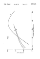
- FIG. 3 graphically represents the expected variation of reflectance as a function of coating thickness for a selectively reflecting silicon dioxide layer, for two different wavelengths.
- FIG. 4 graphically represents lumens as a function of the density of a triphosphor blend in lamps made with and without the selectively reflecting silicon dioxide layer of the present invention.
- FIGS. 5-8 graphically represent lumens as a function of the density of a halophosphate phosphor in lamps made with and without the selectively reflecting silicon dioxide layer of the present invention.
- the performance of mercury vapor discharge lamps can be improved by including a selectively reflecting layer comprising particles of silica (also referred to herein as silicon dioxide) and having a coating weight from about 0.1 to about 4 milligrams per square centimeter.
- the selectively reflecting layer is situated between the envelope and overlying phosphor coating.
- the selectively reflecting layer of the present invention diffusely reflects light by means of one or more scattering events, reflects short-wavelength ultraviolet light to a greater degree than longer-wavelength visible light, and absorbs as little as practicable of the incident light of either type. Apart from the small fraction absorbed,any portion of the incident light that is not reflected is transmitted through the layer.
- a silicon dioxide layer according to the present invention having a weight of 1 mg/cm 2 reflects at least about 83% of the ultraviolet light from the discharge that penetrates the phosphor layer, back into the phosphor layer; and a layer having a weight of 4 mg/cm 2 reflects greater than or equal to about 94% of that light back into the phosphor layer.
- the silicon dioxide layers of the present invention transmit from about 35% to about 96% of the visible light emitted by the phosphor. Since the phosphor and silica layers absorb very little of the emitted visible light, a large fraction of the reflected visible light escapes from the lamp as useful output in subsequent encounters with the phosphor and silica layers. Conversely, the exciting ultraviolet light is strongly absorbed by the phosphor and is much attenuated by each additional transit of the phosphor layer.
- the coating weight for the selectively reflecting silicon dioxide layer is from about 0.1 to about 4 milligrams/square centimeter.
- the optimum thickness of the selectively reflecting silica layer in a particular application is determined by the optical absorption and scattering properties of the phosphor layer to be used with respect to both the exciting and emitted light, as well as whether the maximum visible light output or the maximum reduction in phosphor weight is desired.
- a selectively reflecting silica layer of about 2.5 mg/cm 2 will give themaximum light output
- a selectively reflecting silica layer in the range of about 2.0 to about 4.0 mg/cm 2 will permit the maximum phosphor economy at a fixed light output.
- Approximately half of the maximum saving of phosphor is expected with a selectively reflecting silica layer having a thickness of about 0.4 mg/cm 2 , the exact amountbeing dependent upon the particular phosphor's optical absorption and scattering properties.
- silica layer densities as low as 0.1 mg/cm 2 . This appears to be due to the avoidance of visible light trapping in the glass bulb wall, avoiding the associated excess absorption of that visiblelight.
- the silicon dioxide particles used to form the selectively reflecting silicon dioxide layer, or coating are high purity silicon dioxide, e.g., the silicon dioxide particles preferably comprise at least 99.0% by weightSiO 2 . Most preferably, the silicon dioxide particles comprise greater than or equal to 99.8% by weight SiO 2 .
- the weight percent silicon dioxide represents the degree of purity of the silicon oxide used.
- At least about 80 weight percent of the silicon dioxide particles used to form the selectively reflecting layer of the present invention have a primary particle size from about 5 to about 100 nm with at least 50 weightpercent of the silica having a primary particle size from about 17 to about80 nm.
- at least about 80 weight percent of the silica particles has a primary particle size from about 17 to about 80 nm.
- the preferred particle size distribution peaks at about 50 nm.
- the mercury vapor discharge lamp of the present invention may be, for example, a high pressure mercury vapor discharge lamp or a fluorescent lamp.
- a fluorescent lamp in accordance with the present invention includesan envelope; a discharge assembly including a pair of electrodes sealed in the envelope and a fill comprising an inert gas at a low pressure and a small quantity of mercury; a selectively reflecting silicon dioxide coating deposited on at least a portion of the inner surface of the lamp envelope and a phosphor coating deposited over the selectively reflecting layer.
- the phosphor coating may be further disposed on any uncoated portion of the inner surface of the lamp envelope.
- the selectively reflecting layer is deposited over the entire inner surface of the lamp envelope.
- fluorescent lamp refers to any lamp containing aphosphor excited to fluorescence by ultraviolet radiation, regardless of configuration.
- the fluorescent lamp of the present invention may optionally include additional coatings for various other purposes.
- the fluorescent lamp shown in FIG. 1 comprises an elongated glass, e.g., soda lime silica glass, envelope 1 of circular cross-section. It has the usual electrodes 2 at each end of the envelope 1 supported on lead-in wires.
- the sealed envelope, or tube is filled with an inert gas, such as argon or a mixture of inert gases, such as argon and neon, at a low pressure, for example 2 torr; and a small quantity of mercury is added, at least enough to provide a low vapor pressure of, for example, about six (6) microns during operation.
- an inert gas such as argon or a mixture of inert gases, such as argon and neon
- a low pressure for example 2 torr
- a small quantity of mercury is added, at least enough to provide a low vapor pressure of, for example, about six (6) microns during operation.
- Disposedon the inner surface of the envelope 1 is a selectively reflecting silicon dioxide layer 3 in accordance with the present
- the silicon dioxide reflecting layer can be applied to the envelope by fully coating the inner lamp surface with an organic-base suspension of the above-described silica particles, (including typical binders, surfactants, and solvents).
- an organic base coating suspension may, however, be accompanied by flaking or peeling away of the coating when used to apply thicker coatings, e.g., over 2.5 mg/cm 2 .
- the suspension further includes a negative charge precursor, for example, an aqueous base, such as ammonium hydroxide, to provide a homogeneous dispersion of the silicon dioxide particles in the coating suspension, a first binder, such as poly(ethyleneoxide), a second binder, such as hydroxyethylcellulose, a defoaming agent, a surface active agent, an insolubilizing agent, and a plasticizing agent.
- a negative charge precursor for example, an aqueous base, such as ammonium hydroxide, to provide a homogeneous dispersion of the silicon dioxide particles in the coating suspension
- a first binder such as poly(ethyleneoxide)
- a second binder such as hydroxyethylcellulose
- a defoaming agent such as hydroxyethylcellulose
- a surface active agent such as sodium insolubilizing agent
- plasticizing agent such as sodium phosphor coating
- a water-base silica reflecting coating suspension is prepared by mixing the above-described silica with a mixture of deionized water, ammonium hydroxide, a defoaming agent, a surface active agent, an insolubilizing agent, and a plasticizer to form a slurry.
- the two water-soluble binders are preferably added to the slurry in solution form.
- the foregoing components are mixed together in the order listed.
- Reflectance measurements were conducted on samples of fine particle silica coated to various thicknesses on glass slides using an organic based suspension.
- the slides were prepared by hand mixing small amounts of the fine silica with an organic vehicle similar to that used in preparing organic-based coating suspensions of phosphors.
- the organic vehicle included xylene, butanol, and ethylcellulose.
- the suspension was thinned as needed with additional xylene.
- the coating suspension was applied to the microscope slides which were then allowed to drain and dry in a vertical position.
- the coated slides were baked in air at about 500° C. for 3 to 5 minutes to burn off the organic components. For heavier layers, the process was repeated or a higher concentration of silica was used.
- Curve 10 illustrates reflectance measurements for a silica layer having a density of 1.23 mg/cm 2 ; curve 20 illustrates reflectance measurements for a silica layer having a density of 2.21 mg/cm 2 ; and curve 30 illustrates reflectance measurements for a silica layer having a density of 4.50 mg/cm 2 .
- the fine silica used to obtain the reflectance measurements was Aerosil ® OX-50 obtained from DeGussa, Inc. Aerosil® OX-50 is a fluffy white powder that has a BET surface area of 50 ⁇ 15 m 2 /g. The average primary particle size of OX-50 is 40 nm. Aerosil ® OX-50 contains greater than 99.8 percent SiO 2 , less than 0.08% Al 2 O 3 , less than 0.01% Fe 2 O 3 , less than 0.03 TiO 2 , less than 0.01% HCl.
- FIG. 3 illustrates calculatedvalues for the expected reflectance of layers of OX-50 as a function of layer thickness.
- Curve 40 illustrates expected reflectance as afunction of layer thickness for 254 nm wavelength of light.
- Curve 50 illustrates the expected reflectance as a function of OX-50 layer thickness (mg/cm 2 ) for 555 nm wavelength of light.
- a lamp test was conducted using 40 watt T12 fluorescent lamps. Two sets of lamps were fabricated and tested. The first set consisted of seven (7) groups of lamps, Groups A-G, containing either 3 or 4 lamps per group, in which phosphor coatings of various densities (weight/area) were applied directly to the bare inner surface of the lamp envelope.
- the phosphor usedin the lamp tests was a standard warm white color triphosphor blend including, by weight, 4.6% blue-emitting europium-activated barium magnesium aluminate, 32.4% green-emitting cerium terbium magnesium aluminate, and 63.1% red-emitting europium-activated yttrium oxide.
- the second set consisted of six (6) groups of five lamps each, Groups H-M.
- a selectively reflecting silicon dioxide layer consisting of Aerosil® OX-50 and having a density of 1.7 mg/cm 2 was applied to the entire inner surface of the lamp envelope.
- Phosphor coatings of various densities were applied over the reflecting layer in each of the six groups.
- the same batch of warm white color triphosphor coating suspension was used to form the phosphor layers in both sets of lamps, both with and without the selectively reflecting layers.
- Table I The results from the above-described lamp tests are presented in Table I, below.
- the 100 hours lamp data given in Table I is graphically representedin FIG. 4.
- Curve W represents the results for Lamps A-G (the control group).
- Curve X represents the results for Lamps H-M.
- a second lamp test was conducted in the same fashion as the first, except that the density of the selectively reflecting silica layer was about 2.1 mg/cm 2 and the phosphor was a routine-production cool white, antimonyand manganese-doped calcium fluoro-chlorophosphate phosphor.
- Four (4) other groups of lamps, Groups Q-T were first given the selectively reflecting silicon dioxide coating and baked out before having various densities of the above-identified halophosphate phosphor applied over the silicon dioxide coating.
- the selectively reflecting silicon dioxide layer was suspension-coated using an organic based suspension system containing xylene, butanol, ethylcellulose and surfactant.
- the phosphor coating was also applied using the same organic-based suspension system.
- the present invention can advantageously be utilized with any other phosphor or phosphor blend.
- the present invention may be employed to compensate for the brightness loss caused by the use of a glass not including antimony (about 1-2%) and/or the elimination of cadmium from halophosphatephosphors (about 2%).
- the present invention is particularly advantageous for use in fluorescent lamps which include an antimony-free glass envelope and/or a cadmium-free halophosphate phosphor.
- fluorescent lamps which include an antimony-free glass envelope and/or a cadmium-free halophosphate phosphor.
- the application of a selectively reflecting silica layer beneath a cadmium-free halophosphate layer accounts for an approximately 100% recuperation of brightness lossesassociated with such halophosphates.
- the selectively reflecting layer is applied to the glass envelope at a coating density of about 0.1 to about 0.6 mg/cm 2 , and preferably 0.45 mg/cm 2 , priorto the application of the phosphor layer.
- the use of the selectively reflecting layer in this embodiment increases the total lumen output up toabout 3%.
- the increased lumen output permits a phosphor powder weight reduction per lamp of up to 30% with no loss in lamp brightness. A cost savings is also realized.
- the experiment involved twelve (12) groups of fluorescent lamps of the 40 WattT12 type. Each of the twelve groups contained four (4) lamps.
- Each fluorescent lamp in this experimental series included a selectively reflecting layer having a coating weight in the range of from about 0.5 toabout 1.3 mg/cm 2 and a layer of cool white halophosphate phosphor (containing cadmium) layer with a coating weight in the range of from about 2.4 to about 5.5 mg/cm 2 .
- the actual coating weights for the selectively reflecting layer and phosphor layer included in each of the lamps of the series and the lumen output data for the lamps are summarizedin Table III.
- FIG. 6 graphically represents the brightness (lumens) at 102 hours as a function of phosphor coating weight for three lamp groups of this experimental series.
- Curve 60 represents the results for a lamp group including a selectively reflecting layer with a coating weight of about 0.53 mg/cm 2 .
- Curve 61 represents the results for a lamp group including a selectively reflecting layer with a coating weight of about 0.88 mg/cm 2 .
- Curve 62 represents the results for a lamp group including a selectively reflecting layer with a coating weight of about 1.30 mg/cm 2 .
- the selectively reflecting layer of this experimental series was composed of Aerosil OX-50.
- Lamps including halophosphate phosphor and including a selectively reflecting layer with a coating weight less than about 0.69 mg/cm 2 demonstrated the best results in this experimental series.
- Each fluorescent lamp in three of the groups of this experimental series included a selectively reflecting layer having a coating weight of less than 0.69 mg/cm 2 and a layer of cool white halophosphate phosphor (containing cadmium) layer with a coating weight in the range of from about 3.4 to about 3.7 mg/cm 2 .
- the fourth group was a control group.
- Each fluorescent lamp in the control group included a layer of cool white halophosphate phosphor (containing cadmium). No selectively reflecting layer was included in the lamps of this group.
- the selectively reflecting layer of this experimental series was composed of Aerosil OX-50.
- Each fluorescent lamp in twelve of the groups included a selectively reflecting layer having a coating weight in the range of from about 0.3 toabout 0.64 mg/cm 2 and an overlying layer of cool white halophosphate phosphor (containing cadmium) layer with a coating weight in the range of from about 2.4 to about 5.5 mg/cm 2 .
- the thirteenth group of lamps was a control group.
- Each fluorescent lamp ofthe control group included a single layer of cool white halophosphate phosphor (containing cadmium). No selectively reflecting layer was included in the lamps of this group.
- FIG. 7 graphically represents the brightness (lumens) at 102 hours as a function of phosphor coating weight for four lamp groups of this experimental series.
- Curve 70 represents the results for a lamp group including a selectively reflecting layer with a coating weight of about 0.47 mg/cm 2 .
- Curve 71 represents the results for a lamp group including a selectively reflecting layer with a coating weight of about 0.31 mg/cm 2 .
- Curve 72 represents the results for a lamp group including a selectively reflecting layer with a coating weight of about 0.64 mg/cm 2 .
- Curve 73 represents the results for a lamp group including no selectively reflecting layer. (Point a on curve 73 representsthe data for a lamp including the phosphor coating weight used in a standard commercial 40 Watt T12 cool white fluorescent lamp.)
- the selectively reflecting layer of this experimental series was composed of Aerosil OX-50.
- Each fluorescent lamp in four of the lamp groups included a selectively reflecting layer having a coating weight of about 0.45 mg/cm 2 and an overlying layer of cool white halophosphate phosphor (containing cadmium) layer with a coating weight in the range of from about 2.0 to about 4.8 mg/cm 2 .
- the fifth group of lamps was a control group.
- Each fluorescent lamp in the fifth lamp group included a single layer of cool white halophosphate phosphor (containing cadmium). No selectively reflecting layer was included in the lamps of this group.
- FIG. 8 graphically represents the brightness (lumens) at 102 hours as a function of phosphor coating weight for four lamps of this experimental series.
- Curve 80 represents the results for a lamp group including a selectively reflecting layer with a coating weight of about 0.45 mg/cm 2 .
- Curve 81 represents the results for a lamp group including noselectively reflecting layer. (Point a on curve 81 represents the data for a lamp including the phosphor coating weight as is used in a standard commercial 40 Watt T12 cool white fluorescent lamp.)
- the selectively reflecting layer of this experimental series was composed of Aerosil OX-50.
- Each fluorescent lamp in two of the lamp groups of this experimental seriesin cluded a selectively reflecting layer having a coating weight of about 0.49 mg/cm 2 and an overlying layer of cadmium-free cool white halophosphate phosphor.
- the selectively reflecting layer of this experimental series was composed of Aerosil OX-50.
- Each fluorescent lamp in the other two lamp groups of this experimental series included a single layer of cadmium-containing cool white halophosphate phosphor layer. No selectively reflecting layer was includedin the lamps of the second group.
- the density values for the selectively reflecting layers and the phosphor layers described in Examples 3-7 and the respective Tables are based upon a surface area of 1,473 cm 2 .
- the lamps tested in Examples 3-7 employed lamp envelopes comprised of antimony-free glass.
- lamps include a discharge assembly which includes a quartz arc tube.
- the arc tube includes a pair ofspaced electrodes and a discharge-sustaining fill including mercury and an inert starting gas.
- These lamps also include means for electrically connecting the arc tube electrodes to a pair of lead-ins which are connected to the contacts of the base.
- These lamps may further include support means (e.g., a frame) for supporting the arc tube within the outerenvelope.
- a significant portion of the radiant energy generated by the mercury arc of a high pressure mercury vapor type lamp is in the ultraviolet region.
- Phosphor coatings are used in these lamps to convert some of the ultraviolet light to visible light.
- Red or red-orange-emitting phosphors or phosphor blends, especially europium-doped yttrium vanadate or phosphovanadates, are typically used in high pressure mercury vapor type lamps to improve the efficacy and color rendition of the lamp output.
- a selectively reflecting silicon dioxide layer is interposed between the inner surface of the outer jacket and the phosphor layer.
Landscapes
- Vessels And Coating Films For Discharge Lamps (AREA)
- Measuring Or Testing Involving Enzymes Or Micro-Organisms (AREA)
Abstract
An improved mercury vapor discharge lamp is disclosed. The lamp of the present invention includes an envelope and a selectively reflecting silicon dioxide layer on at least a portion of the inner surface of the envelope. The lamp further includes a phosphor coating disposed on the selectively reflecting layer. The silicon dioxide layer has a coating weight of from about 0.1 to about 4 mg/cm2. The selectively reflecting layer comprises at least about 80 weight percent silica having a primary particle size from about 5 to about 100 nm with at least about 50 weight percent of the silica having a primary particle size from about 17 to about 80 nm.
Description
This application is a continuation-in-part of application Ser. No. 062,262 filed on June 12, 1987 now abandoned.
The present invention relates to mercury vapor discharge lamps and more particularly to mercury vapor discharge lamps including a reflector layer.
Various coatings of non-luminescent particulate materials have been found to be useful when applied as an undercoating for the phosphor layer in both fluorescent and other mercury vapor lamps. In both types of lamp, the phosphor coating is disposed on the inner surface of the lamp glass envelope in receptive proximity to the ultraviolet radiation being generated by the mercury discharge.
Examples of non-luminescent particulate materials which have been used as reflector layers in fluorescent lamps such as, for example, aperture fluorescent reprographic lamps, include titanium dioxide, mixtures of titanium dioxide and up to 15 weight percent aluminum oxide; zirconium oxide; aluminum oxide; aluminum; and silver. Titanium dioxide is typically used to form the reflector layer in commercially available aperture fluorescent reprographic lamps.
In some instances a layer of non-luminescent particulate material is used to permit reduction in the phosphor coating weight. See, for example, U.S. Pat. No. 4,079,288 to Maloney et al., issued on 14 March 1978. U.S. Pat. No. 4,074,288 discloses employing a reflector layer comprising vapor-formed spherical alumina particles having an individual particle size range from about 400 to 5000 Angstroms in diameter in fluorescent lamps to enable reduction in phosphor coating weight with minor lumen loss. The lamp data set forth in the patent, however, shows an appreciable drop in lumen output at 100 hours.
U.S. Pat. No. 4,344,016 to Hoffman et al., issued on 10 August 1982 discloses a low pressure mercury vapor discharge lamp having an SiO2 coating having a thickness of 0.05 to 0.7 mg/cm2. U.S. Pat. No. 4,344,016 expressly provides that the use of thicker coatings causes a reduction in the luminous efficacy due to the occurrence of an absorption of the visible light.
In accordance with the present invention, there is provided a mercury vapor discharge lamp comprising a lamp envelope having an inner surface; a discharge assembly; a selectively reflecting layer disposed on at least a portion of the inner surface of the lamp envelope at a coating weight from about 0.1 to about 4 mg/cm2, the selectively reflecting layer comprising at least about 80 weight percent silica having a primary particle size from about 5 to about 100 nm with at least about 50 weight percent of the silica having a primary particle size from about 17 to about 80 nm; and a phosphor coating disposed over at least the selectively reflecting layer.
In the drawings:
FIG. 1 is an elevational view of a fluorescent lamp, partly in cross section, in accordance with one embodiment of the present invention.
FIG. 2 graphically represents reflectance measurements of a silicon dioxide coating in accordance with the present invention as a function of wavelength at different coating thicknesses.
FIG. 3 graphically represents the expected variation of reflectance as a function of coating thickness for a selectively reflecting silicon dioxide layer, for two different wavelengths.
FIG. 4 graphically represents lumens as a function of the density of a triphosphor blend in lamps made with and without the selectively reflecting silicon dioxide layer of the present invention.
FIGS. 5-8 graphically represent lumens as a function of the density of a halophosphate phosphor in lamps made with and without the selectively reflecting silicon dioxide layer of the present invention.
For a better understanding of the present invention, together with other and further objects, advantages, and capabilities thereof, reference is made to the following disclosure and appended claims in connection with the above-described drawings.
In accordance with the present invention, it has been found that the performance of mercury vapor discharge lamps can be improved by including a selectively reflecting layer comprising particles of silica (also referred to herein as silicon dioxide) and having a coating weight from about 0.1 to about 4 milligrams per square centimeter. The selectively reflecting layer is situated between the envelope and overlying phosphor coating. The selectively reflecting layer of the present invention diffusely reflects light by means of one or more scattering events, reflects short-wavelength ultraviolet light to a greater degree than longer-wavelength visible light, and absorbs as little as practicable of the incident light of either type. Apart from the small fraction absorbed,any portion of the incident light that is not reflected is transmitted through the layer.
For example, a silicon dioxide layer according to the present invention, having a weight of 1 mg/cm2 reflects at least about 83% of the ultraviolet light from the discharge that penetrates the phosphor layer, back into the phosphor layer; and a layer having a weight of 4 mg/cm2reflects greater than or equal to about 94% of that light back into the phosphor layer. The silicon dioxide layers of the present invention transmit from about 35% to about 96% of the visible light emitted by the phosphor. Since the phosphor and silica layers absorb very little of the emitted visible light, a large fraction of the reflected visible light escapes from the lamp as useful output in subsequent encounters with the phosphor and silica layers. Conversely, the exciting ultraviolet light is strongly absorbed by the phosphor and is much attenuated by each additional transit of the phosphor layer.
As provided above, the coating weight for the selectively reflecting silicon dioxide layer is from about 0.1 to about 4 milligrams/square centimeter.
The optimum thickness of the selectively reflecting silica layer in a particular application is determined by the optical absorption and scattering properties of the phosphor layer to be used with respect to both the exciting and emitted light, as well as whether the maximum visible light output or the maximum reduction in phosphor weight is desired. For typical commercial lamp phosphors, it is expected that a selectively reflecting silica layer of about 2.5 mg/cm2 will give themaximum light output, while a selectively reflecting silica layer in the range of about 2.0 to about 4.0 mg/cm2 will permit the maximum phosphor economy at a fixed light output. Approximately half of the maximum saving of phosphor is expected with a selectively reflecting silica layer having a thickness of about 0.4 mg/cm2, the exact amountbeing dependent upon the particular phosphor's optical absorption and scattering properties.
However, it has been unexpectedly found that substantial phosphor savings may be realized with silica layer densities as low as 0.1 mg/cm2. This appears to be due to the avoidance of visible light trapping in the glass bulb wall, avoiding the associated excess absorption of that visiblelight.
The silicon dioxide particles used to form the selectively reflecting silicon dioxide layer, or coating, are high purity silicon dioxide, e.g., the silicon dioxide particles preferably comprise at least 99.0% by weightSiO2. Most preferably, the silicon dioxide particles comprise greater than or equal to 99.8% by weight SiO2. The weight percent silicon dioxide represents the degree of purity of the silicon oxide used.
At least about 80 weight percent of the silicon dioxide particles used to form the selectively reflecting layer of the present invention have a primary particle size from about 5 to about 100 nm with at least 50 weightpercent of the silica having a primary particle size from about 17 to about80 nm. Preferably, at least about 80 weight percent of the silica particleshas a primary particle size from about 17 to about 80 nm. Most preferably, the preferred particle size distribution peaks at about 50 nm.
The mercury vapor discharge lamp of the present invention may be, for example, a high pressure mercury vapor discharge lamp or a fluorescent lamp.
In accordance with one embodiment of the present invention, such selectively reflecting silicon dioxide layer is included in a fluorescent lamp. A fluorescent lamp in accordance with the present invention includesan envelope; a discharge assembly including a pair of electrodes sealed in the envelope and a fill comprising an inert gas at a low pressure and a small quantity of mercury; a selectively reflecting silicon dioxide coating deposited on at least a portion of the inner surface of the lamp envelope and a phosphor coating deposited over the selectively reflecting layer. The phosphor coating may be further disposed on any uncoated portion of the inner surface of the lamp envelope. In a preferred embodiment, the selectively reflecting layer is deposited over the entire inner surface of the lamp envelope.
As used herein, the term "fluorescent lamp" refers to any lamp containing aphosphor excited to fluorescence by ultraviolet radiation, regardless of configuration.
The fluorescent lamp of the present invention may optionally include additional coatings for various other purposes.
Referring to FIG. 1, there is shown an example of a fluorescent lamp embodiment of the present invention. The fluorescent lamp shown in FIG. 1 comprises an elongated glass, e.g., soda lime silica glass, envelope 1 of circular cross-section. It has the usual electrodes 2 at each end of the envelope 1 supported on lead-in wires. The sealed envelope, or tube, is filled with an inert gas, such as argon or a mixture of inert gases, such as argon and neon, at a low pressure, for example 2 torr; and a small quantity of mercury is added, at least enough to provide a low vapor pressure of, for example, about six (6) microns during operation. Disposedon the inner surface of the envelope 1 is a selectively reflecting silicon dioxide layer 3 in accordance with the present invention. A phosphor layer4 is coated over the reflective silicon dioxide coating.
The silicon dioxide reflecting layer can be applied to the envelope by fully coating the inner lamp surface with an organic-base suspension of the above-described silica particles, (including typical binders, surfactants, and solvents). The use of an organic base coating suspension may, however, be accompanied by flaking or peeling away of the coating when used to apply thicker coatings, e.g., over 2.5 mg/cm2.
Such flaking or peeling problems are inhibited when the silicon dioxide reflecting layer of the present invention is applied to the envelope from a water-base suspension of the above-described silicon dioxide particles. The water-base coating suspension is described in more complete detail in U.S. patent application Ser. No. 062,263 of Cheryl A. Ford entitled "Fine Particle Size Powder Coating Suspension and Method" filed on even date herewith and assigned to the present assignee, the specification of which is incorporated herein by reference. The suspension further includes a negative charge precursor, for example, an aqueous base, such as ammonium hydroxide, to provide a homogeneous dispersion of the silicon dioxide particles in the coating suspension, a first binder, such as poly(ethyleneoxide), a second binder, such as hydroxyethylcellulose, a defoaming agent, a surface active agent, an insolubilizing agent, and a plasticizing agent.The coated envelope is then heated to cure the coating during the bulb drying step. The phosphor coating is applied thereover by conventional lamp processing techniques.
More particularly, a water-base silica reflecting coating suspension is prepared by mixing the above-described silica with a mixture of deionized water, ammonium hydroxide, a defoaming agent, a surface active agent, an insolubilizing agent, and a plasticizer to form a slurry. The two water-soluble binders are preferably added to the slurry in solution form.
An example of a water-base coating suspension useful in applying a selectively reflecting layer in accordance with the present invention is prepared from the following components:
______________________________________
150    cc      deionized water
12     cc      ammonium hydroxide Reagent Grade
               Assay (28-31%)
0.28   cc      defoaming agent (Hercules type 831)
0.028  cc      surfactant (BASF type 25R-1 Pluronic)
2.5    cc      glycerine
0.45   g       dimethylolurea
150    g       Aerosil.sup.R OX-50 (obtained from DeGussa,
               Inc.)
100    cc      hydroxyethylcellulose soltuion containing
               1.7 weight percent of the resin (Natrosol
               (HEC) grade 250 MBR obtained from
               Hercules) in water
600    cc      poly (ethylene oxide) solution containing
               2.2 weight percent of the resin (WSRN 2000
               obtained from Union Carbide) in water
______________________________________
Preferably, the foregoing components are mixed together in the order listed.
Reflectance measurements were conducted on samples of fine particle silica coated to various thicknesses on glass slides using an organic based suspension. The slides were prepared by hand mixing small amounts of the fine silica with an organic vehicle similar to that used in preparing organic-based coating suspensions of phosphors. The organic vehicle included xylene, butanol, and ethylcellulose. The suspension was thinned as needed with additional xylene. The coating suspension was applied to the microscope slides which were then allowed to drain and dry in a vertical position. The coated slides were baked in air at about 500° C. for 3 to 5 minutes to burn off the organic components. For heavier layers, the process was repeated or a higher concentration of silica was used.
The results are graphically represented in FIG. 2. Curve 10 illustrates reflectance measurements for a silica layer having a density of 1.23 mg/cm2 ; curve 20 illustrates reflectance measurements for a silica layer having a density of 2.21 mg/cm2 ; and curve 30 illustrates reflectance measurements for a silica layer having a density of 4.50 mg/cm2. The fine silica used to obtain the reflectance measurements was Aerosil ® OX-50 obtained from DeGussa, Inc. Aerosil® OX-50 is a fluffy white powder that has a BET surface area of 50±15 m2 /g. The average primary particle size of OX-50 is 40 nm. Aerosil ® OX-50 contains greater than 99.8 percent SiO2, less than 0.08% Al2 O3, less than 0.01% Fe2 O3, less than 0.03 TiO2, less than 0.01% HCl.
While FIG. 2 illustrates experimental values, FIG. 3 illustrates calculatedvalues for the expected reflectance of layers of OX-50 as a function of layer thickness. In FIG. 3, Curve 40 illustrates expected reflectance as afunction of layer thickness for 254 nm wavelength of light. Curve 50 illustrates the expected reflectance as a function of OX-50 layer thickness (mg/cm2) for 555 nm wavelength of light.
A lamp test was conducted using 40 watt T12 fluorescent lamps. Two sets of lamps were fabricated and tested. The first set consisted of seven (7) groups of lamps, Groups A-G, containing either 3 or 4 lamps per group, in which phosphor coatings of various densities (weight/area) were applied directly to the bare inner surface of the lamp envelope. The phosphor usedin the lamp tests was a standard warm white color triphosphor blend including, by weight, 4.6% blue-emitting europium-activated barium magnesium aluminate, 32.4% green-emitting cerium terbium magnesium aluminate, and 63.1% red-emitting europium-activated yttrium oxide.
The second set consisted of six (6) groups of five lamps each, Groups H-M. In each of the six groups, a selectively reflecting silicon dioxide layer consisting of Aerosil® OX-50 and having a density of 1.7 mg/cm2 was applied to the entire inner surface of the lamp envelope. Phosphor coatings of various densities were applied over the reflecting layer in each of the six groups. The same batch of warm white color triphosphor coating suspension was used to form the phosphor layers in both sets of lamps, both with and without the selectively reflecting layers.
The results from the above-described lamp tests are presented in Table I, below. The 100 hours lamp data given in Table I is graphically representedin FIG. 4. Curve W represents the results for Lamps A-G (the control group). Curve X represents the results for Lamps H-M.
                                  TABLE I
__________________________________________________________________________
          PHOSPHOR
                 AVERAGE LUMEN OUTPUT
LAMP NO. OF
          DENSITY
                 Zero hr.
                      100-hr.
                            3139 hr.
                                 MAINTENANCE
GROUP
     LAMPS
          mg/cm.sup.2
                 (lumens)
                      (lumens)
                            (lumens)
                                 0-100 hr.
                                      100-3139 hr.
__________________________________________________________________________
A    4    3.09   3489 3468  3117 99.4%
                                      89.9%
B    3    2.67   3429 3371  --   98.3%
                                      --
C    3    2.42   3355 3271  --   97.5%
                                      --
D    3    1.80   3070 2992  --   97.5%
                                      --
E    3    1.35   2661 2545  --   95.6%
                                      --
F    3    1.11   2317 2148  --   92.7%
                                      --
G    3    1.00   2141 1975  --   92.2%
                                      --
H    5    3.51   3619 3560  3361 98.4%
                                      94.4%
I    5    3.03   3634 3592  3352 98.8%
                                      92.3%
J    5    2.33   3620 3559  3298 98.3%
                                      92.7%
K    5    1.79   3546 3471  3159 97.9%
                                      92.7%
L    5    1.52   3439 3314  2867 96.4%
                                      91.0%
M    5    1.25   3295 3180  --   96.5%
                                      --
__________________________________________________________________________
A second lamp test was conducted in the same fashion as the first, except that the density of the selectively reflecting silica layer was about 2.1 mg/cm2 and the phosphor was a routine-production cool white, antimonyand manganese-doped calcium fluoro-chlorophosphate phosphor. Three (3) groups of lamps, Groups N-P, consisting of four (4) lamps each, were coated with various densities of the phosphor, applied directly to the bare inner surface of the lamp envelope. Four (4) other groups of lamps, Groups Q-T, were first given the selectively reflecting silicon dioxide coating and baked out before having various densities of the above-identified halophosphate phosphor applied over the silicon dioxide coating. In lamp Groups Q-T, the selectively reflecting silicon dioxide layer was suspension-coated using an organic based suspension system containing xylene, butanol, ethylcellulose and surfactant. In lamp Groups N-P and Q-T, the phosphor coating was also applied using the same organic-based suspension system.
The results of this lamp test are presented in Table II. The 101 hour lumendata is graphically presented in FIG. 5, where curve Y represents the results for lamp groups N-P (the control groups), and curve Z represents the results for Groups Q-T which include the selectively reflecting silicon dioxide layer, according to the present invention.
                                  TABLE II
__________________________________________________________________________
          PHOSPHOR
                 AVERAGE LUMEN OUTPUT
LAMP NO. OF
          DENSITY
                 Zero hr.
                      101 hr.
                            335 hr.
                                 0-101 hrs.
GROUP
     LAMPS
          mg/cm.sup.2
                 (lumens)
                      (lumens)
                            (lumens)
                                 Maintenance
__________________________________________________________________________
N    4    6.5    3147 3008  2932 95.6%
O    4    5.1    3300 3074  2983 96.1%
P    4    3.4    3113 2852  2788 91.6%
Q    4    6.3    3208 3089  2932 96.3%
R    4    4.7    3238 3096  2992 95.6%
S    4    3.3    3313 3065  2976 92.5%
T    4    2.0    3155 2907  2780 92.1%
__________________________________________________________________________
Although the above-described tests involve a warm white triphosphor blend and a halophosphate phosphor, the present invention can advantageously be utilized with any other phosphor or phosphor blend.
Among other purposes, the present invention may be employed to compensate for the brightness loss caused by the use of a glass not including antimony (about 1-2%) and/or the elimination of cadmium from halophosphatephosphors (about 2%).
Accordingly, the present invention is particularly advantageous for use in fluorescent lamps which include an antimony-free glass envelope and/or a cadmium-free halophosphate phosphor. For example, the application of a selectively reflecting silica layer beneath a cadmium-free halophosphate layer accounts for an approximately 100% recuperation of brightness lossesassociated with such halophosphates.
In an embodiment of the present invention including an antimony-free glass envelope and/or cadmium-free halophosphate phosphor, the selectively reflecting layer is applied to the glass envelope at a coating density of about 0.1 to about 0.6 mg/cm2, and preferably 0.45 mg/cm2, priorto the application of the phosphor layer. The use of the selectively reflecting layer in this embodiment increases the total lumen output up toabout 3%. The increased lumen output permits a phosphor powder weight reduction per lamp of up to 30% with no loss in lamp brightness. A cost savings is also realized.
A series of experiments was carried out employing fluorescent lamps. The experiment involved twelve (12) groups of fluorescent lamps of the 40 WattT12 type. Each of the twelve groups contained four (4) lamps. Each fluorescent lamp in this experimental series included a selectively reflecting layer having a coating weight in the range of from about 0.5 toabout 1.3 mg/cm2 and a layer of cool white halophosphate phosphor (containing cadmium) layer with a coating weight in the range of from about 2.4 to about 5.5 mg/cm2. The actual coating weights for the selectively reflecting layer and phosphor layer included in each of the lamps of the series and the lumen output data for the lamps are summarizedin Table III.
FIG. 6 graphically represents the brightness (lumens) at 102 hours as a function of phosphor coating weight for three lamp groups of this experimental series. Curve 60 represents the results for a lamp group including a selectively reflecting layer with a coating weight of about 0.53 mg/cm2. Curve 61 represents the results for a lamp group including a selectively reflecting layer with a coating weight of about 0.88 mg/cm2. Curve 62 represents the results for a lamp group including a selectively reflecting layer with a coating weight of about 1.30 mg/cm2.
                                  TABLE III
__________________________________________________________________________
        Reflecting
        Layer Phosphor         Lumen Maintenance
Lamp
    No. of
        Density
              Density
                   Average Lumen Output
                               0-102
                                    102-4987
Group
    Lamps
        mg/cm.sup.2
              mg/cm.sup.2
                   0 Hr
                      102 Hr
                          4989 Hr
                               % M  % M
__________________________________________________________________________
U   4   0.53  3.20 3221
                      3059
                          2738 95.0 89.5
V   4   0.53  3.78 3219
                      3111
                          2858 96.6 91.9
W   4   0.53  5.37 3243
                      3117
                          2753 96.1 88.3
X   4   0.53  5.05 3257
                      3134
                          2810 96.2 89.7
Y   4   0.88  2.72 3232
                      3061
                          2676 94.7 87.4
Z   4   0.88  3.30 3242
                      3077
                          2644 94.9 85.9
AA  4   0.88  3.76 3242
                      3094
                          2689 95.4 86.9
BB  4   0.88  4.25 3254
                      3107
                          2682 95.5 86.3
CC  4   1.30  2.64 3249
                      3044
                          2606 93.7 85.6
DD  4   1.30  2.75 3231
                      3052
                          2604 94.5 85.3
EE  4   1.30  3.35 3259
                      3079
                          2634 94.5 85.6
FF  4   1.30  3.63 3258
                      3087
                          2570 94.8 83.3
__________________________________________________________________________
The selectively reflecting layer of this experimental series was composed of Aerosil OX-50.
Lamps including halophosphate phosphor and including a selectively reflecting layer with a coating weight less than about 0.69 mg/cm2 demonstrated the best results in this experimental series.
A series of experiments was carried out employing fluorescent lamps. The experiment involved four groups of fluorescent lamps of the 40 Watt T12 type.
Each fluorescent lamp in three of the groups of this experimental series included a selectively reflecting layer having a coating weight of less than 0.69 mg/cm2 and a layer of cool white halophosphate phosphor (containing cadmium) layer with a coating weight in the range of from about 3.4 to about 3.7 mg/cm2.
The fourth group was a control group. Each fluorescent lamp in the control group included a layer of cool white halophosphate phosphor (containing cadmium). No selectively reflecting layer was included in the lamps of this group.
The selectively reflecting layer of this experimental series was composed of Aerosil OX-50.
The actual coating weights for the lamps of the series and the lumen outputdata for each lamp are summarized in Table IV.
                                  TABLE IV
__________________________________________________________________________
Reflecting
Layer     Phosphor         Lumen Maintenance
Lamp
    Density
          Density
               Average Lumen Output
                           0-98 98-8010
Group
    mg/cm.sup.2
          mg/cm.sup.2
               0 Hr
                  98 Hr
                      8010 Hr
                           % M  % M
__________________________________________________________________________
GG  --    4.39 3193
                  3095
                      2670 96.9 86.3
HH  0.42  3.49 3258
                  3142
                      2663 96.4 84.8
II  0.42  3.36 3249
                  3145
                      2623 96.8 83.4
JJ  0.42  3.72 3268
                  3155
                      2623 96.5 83.1
__________________________________________________________________________
A series of experiments was carried out employing fluorescent lamps. The experiment involved thirteen groups of fluorescent lamps of the 40 Watt T12 type.
Each fluorescent lamp in twelve of the groups included a selectively reflecting layer having a coating weight in the range of from about 0.3 toabout 0.64 mg/cm2 and an overlying layer of cool white halophosphate phosphor (containing cadmium) layer with a coating weight in the range of from about 2.4 to about 5.5 mg/cm2.
The thirteenth group of lamps was a control group. Each fluorescent lamp ofthe control group included a single layer of cool white halophosphate phosphor (containing cadmium). No selectively reflecting layer was included in the lamps of this group.
FIG. 7 graphically represents the brightness (lumens) at 102 hours as a function of phosphor coating weight for four lamp groups of this experimental series. Curve 70 represents the results for a lamp group including a selectively reflecting layer with a coating weight of about 0.47 mg/cm2. Curve 71 represents the results for a lamp group including a selectively reflecting layer with a coating weight of about 0.31 mg/cm2. Curve 72 represents the results for a lamp group including a selectively reflecting layer with a coating weight of about 0.64 mg/cm2. Curve 73 represents the results for a lamp group including no selectively reflecting layer. (Point a on curve 73 representsthe data for a lamp including the phosphor coating weight used in a standard commercial 40 Watt T12 cool white fluorescent lamp.)
                                  TABLE V
__________________________________________________________________________
        Reflecting
        Layer Phosphor         Lumen Maintenance
Lamp
    No. of
        Density
              Density
                   Average Lumen Output
                               0-102
                                    102-4987
Group
    Lamps
        mg/cm.sup.2
              mg/cm.sup.2
                   0 Hr
                      102 Hr
                          4989 Hr
                               % M  % M
__________________________________________________________________________
KK  5   0.64  2.40 3165
                      2971
                          2561 93.9 86.2
LL  5   0.64  2.91 3208
                      3044
                          2618 94.9 90.2
MM  5   0.64  2.72 3210
                      3031
                          2644 94.4 87.2
NN  5   0.64  4.91 3320
                      3142
                          2583 94.6 82.2
OO  5   0.47  2.56 3196
                      3036
                          2672 95.0 88.0
PP  5   0.47  2.79 3225
                      3061
                          2711 94.9 88.5
QQ  4   0.47  5.17 3283
                      3158
                          2606 96.2 82.5
RR  5   0.47  5.40 3283
                      3140
                          2610 95.6 83.1
SS  5   0.31  2.49 3166
                      2995
                          2644 94.6 88.2
TT  5   0.31  2.92 3191
                      3037
                          2681 95.2 88.3
UU  5   0.31  5.04 3314
                      3143
                          2633 94.8 83.8
VV  5   0.31  5.21 3288
                      3147
                          2654 95.7 84.3
WW  5   --    3.93 3234
                      3063
                          2734 94.7 89.3
__________________________________________________________________________
The selectively reflecting layer of this experimental series was composed of Aerosil OX-50.
The number of lamps in each group, the actual coating weights for the lampsof the series, and the lumen output data for each lamp in this series are summarized in Table V.
A series of experiments was carried out employing fluorescent lamps. The experiment involved five groups of fluorescent lamps of the 40 Watt T12 type.
Each fluorescent lamp in four of the lamp groups included a selectively reflecting layer having a coating weight of about 0.45 mg/cm2 and an overlying layer of cool white halophosphate phosphor (containing cadmium) layer with a coating weight in the range of from about 2.0 to about 4.8 mg/cm2.
The fifth group of lamps was a control group. Each fluorescent lamp in the fifth lamp group included a single layer of cool white halophosphate phosphor (containing cadmium). No selectively reflecting layer was included in the lamps of this group.
FIG. 8 graphically represents the brightness (lumens) at 102 hours as a function of phosphor coating weight for four lamps of this experimental series. Curve 80 represents the results for a lamp group including a selectively reflecting layer with a coating weight of about 0.45 mg/cm2. Curve 81 represents the results for a lamp group including noselectively reflecting layer. (Point a on curve 81 represents the data for a lamp including the phosphor coating weight as is used in a standard commercial 40 Watt T12 cool white fluorescent lamp.)
The selectively reflecting layer of this experimental series was composed of Aerosil OX-50.
The number of lamps in each group, the actual coating weights for the lampsof the series, and the lumen output data for each lamp are summarized in Table VI.
A series of experiments was carried out employing fluorescent lamps. The experiment involved four groups of fluorescent lamps of the 40 Watt T12 type.
Each fluorescent lamp in two of the lamp groups of this experimental seriesincluded a selectively reflecting layer having a coating weight of about 0.49 mg/cm2 and an overlying layer of cadmium-free cool white halophosphate phosphor.
                                  TABLE VI
__________________________________________________________________________
        Reflecting
        Layer Phosphor         Lumen Maintenance
Lamp
    No. of
        Density
              Density
                   Average Lumen Output
                               0-102
                                    102-4987
Group
    Lamps
        mg/cm.sup.2
              mg/cm.sup.2
                   0 Hr
                      102 Hr
                          4989 Hr
                               % M  % M
__________________________________________________________________________
XX  6   0.45  4.71 3277
                      3157
                          2875 96.3 91.1
YY  7   0.45  3.62 3260
                      3158
                          2950 96.9 93.4
ZZ  7   0.45  2.94 3250
                      3100
                          2894 95.4 93.4
AAA 6   0.45  2.34 3180
                      3047
                          2831 95.8 92.9
BBB 8   --    3.56 3190
                      3043
                          2779 95.4 91.3
__________________________________________________________________________
The selectively reflecting layer of this experimental series was composed of Aerosil OX-50.
Each fluorescent lamp in the other two lamp groups of this experimental series included a single layer of cadmium-containing cool white halophosphate phosphor layer. No selectively reflecting layer was includedin the lamps of the second group.
The data for this lamp test is set forth in Table VII.
The results show that a selectively reflecting layer, when used with cadmium-free cool white phosphor compensates for intrinsic brightness losses associated with cadmium-free halophosphates.
The density values for the selectively reflecting layers and the phosphor layers described in Examples 3-7 and the respective Tables are based upon a surface area of 1,473 cm2.
The lamps tested in Examples 3-7 employed lamp envelopes comprised of antimony-free glass.
While the foregoing lamp tests involved fluorescent, or low pressure mercury discharge lamps, it is believed that the selectively reflecting silicon dioxide layer of the present invention will provide similar advantages when employed on the inner surface of the vitreous outer envelope, or jacket, of a high pressure mercury vapor lamp, the structuresof which are well known in the art. These lamps include a discharge assembly which includes a quartz arc tube. The arc tube includes a pair ofspaced electrodes and a discharge-sustaining fill including mercury and an inert starting gas. These lamps also include means for electrically connecting the arc tube electrodes to a pair of lead-ins which are connected to the contacts of the base. These lamps may further include support means (e.g., a frame) for supporting the arc tube within the outerenvelope.
                                  TABLE VII
__________________________________________________________________________
    OX-50      Cool
Lamp
    Pre-Coat Wt.
           No. of
               White Wt.
                     Total                105-2999
Group
    (grams)
           Lamps
               (grams)
                     Density
                          0 Hr
                             105 Hr
                                 489 Hr
                                     2999 Hr
                                          % M
__________________________________________________________________________
CCC --     5   5.11  78.5 3156
                             3075
                                 3003
                                     2796 90.9
DDD --     7   6.20  78.3 3111
                             3036
                                 2949
                                     2745 90.4
EEE 0.71   6   5.87  78.7 3261
                             3138
                                 3061
                                     2861 91.2
FFF 0.71   6   5.09  78.0 3228
                             3127
                                 3033
                                     2825 90.3
__________________________________________________________________________
A significant portion of the radiant energy generated by the mercury arc ofa high pressure mercury vapor type lamp is in the ultraviolet region. Phosphor coatings are used in these lamps to convert some of the ultraviolet light to visible light. Red or red-orange-emitting phosphors or phosphor blends, especially europium-doped yttrium vanadate or phosphovanadates, are typically used in high pressure mercury vapor type lamps to improve the efficacy and color rendition of the lamp output. In accordance with the present invention, a selectively reflecting silicon dioxide layer is interposed between the inner surface of the outer jacket and the phosphor layer.
While there have been shown and described what are considered preferred embodiments of the present invention, it will be apparent to those skilledin the art that various changes and modifications may be made therein without departing from the invention as defined by the appended Claims.
Claims (3)
1. A fluorescent lamp comprising:
a lamp envelope having an inner surface;
a selectively reflecting layer comprising silica disposed on at least a portion of said inner surface of said envelope at a coating weight from about 0.1 to about 4 mg/cm2, said selectively reflecting layer comprising at least about 80 weight percent silica having a primary particle size from about 5 to about 100 nm with at least about 50 weight percent of said silica having a primary particle size from about 17 to about 80 nm;
a phosphor coating disposed over said selectively reflecting layer and on any uncoated portion of said inner surface of said lamp; and
said selectively reflecting layer contains greater than or equal to 1.0 mg/cm2 of silica.
2. A fluorescent lamp in accordance with claim 1 wherein said selectively reflecting layer contains about 2.0 to about 4.0 mg/cm2 of silica.
3. A fluorescent lamp in accordance with claim 1 wherein said selectively reflecting layer contains about 2.5 mg/cm2 of silica.
Priority Applications (5)
| Application Number | Priority Date | Filing Date | Title |
|---|---|---|---|
| US07/199,152 US5051653A (en) | 1987-06-12 | 1988-06-02 | Silicon dioxide selectively reflecting layer for mercury vapor discharge lamps |
| JP63505780A JPH01503662A (en) | 1987-06-12 | 1988-06-10 | Silicon dioxide layer for selective reflection for mercury vapor discharge lamps |
| EP19880906372 EP0318578A4 (en) | 1987-06-12 | 1988-06-10 | Silicon dioxide selectively reflecting layer for mercury vapor discharge lamps. |
| PCT/US1988/001991 WO1988010005A1 (en) | 1987-06-12 | 1988-06-10 | Silicon dioxide selectively reflecting layer for mercury vapor discharge lamps |
| CA000569255A CA1296379C (en) | 1987-06-12 | 1988-06-10 | Silicon dioxide selectively reflecting layer for mercury vapor discharge lamps |
Applications Claiming Priority (2)
| Application Number | Priority Date | Filing Date | Title |
|---|---|---|---|
| US6226287A | 1987-06-12 | 1987-06-12 | |
| US07/199,152 US5051653A (en) | 1987-06-12 | 1988-06-02 | Silicon dioxide selectively reflecting layer for mercury vapor discharge lamps |
Related Parent Applications (1)
| Application Number | Title | Priority Date | Filing Date |
|---|---|---|---|
| US6226287A Continuation-In-Part | 1987-06-12 | 1987-06-12 |
Publications (1)
| Publication Number | Publication Date |
|---|---|
| US5051653A true US5051653A (en) | 1991-09-24 |
Family
ID=26742044
Family Applications (1)
| Application Number | Title | Priority Date | Filing Date |
|---|---|---|---|
| US07/199,152 Expired - Lifetime US5051653A (en) | 1987-06-12 | 1988-06-02 | Silicon dioxide selectively reflecting layer for mercury vapor discharge lamps |
Country Status (5)
| Country | Link |
|---|---|
| US (1) | US5051653A (en) |
| EP (1) | EP0318578A4 (en) |
| JP (1) | JPH01503662A (en) |
| CA (1) | CA1296379C (en) |
| WO (1) | WO1988010005A1 (en) |
Cited By (13)
| Publication number | Priority date | Publication date | Assignee | Title |
|---|---|---|---|---|
| US5473226A (en) * | 1993-11-16 | 1995-12-05 | Osram Sylvania Inc. | Incandescent lamp having hardglass envelope with internal barrier layer |
| KR960706187A (en) * | 1994-08-25 | 1996-11-08 | 제이.지.에이. 롤페즈 | Low-pressure mercury vapour discharge lamp |
| US5731658A (en) * | 1994-11-30 | 1998-03-24 | Honeywell Inc. | Ultraviolet binder for phosphor fluorescent light box |
| US5869927A (en) * | 1995-07-31 | 1999-02-09 | Matsushita Electronics Corporation | Fluorescent lamp with a mixed layer containing phosphor and metal oxide |
| US6069441A (en) * | 1996-10-31 | 2000-05-30 | Honeywell Inc. | Method for producing phospher binding materials |
| US6400097B1 (en) * | 2001-10-18 | 2002-06-04 | General Electric Company | Low wattage fluorescent lamp |
| WO2002037534A3 (en) * | 2000-10-30 | 2002-09-06 | Gen Electric | Low wattage fluorescent lamp |
| US6534910B1 (en) * | 2000-09-06 | 2003-03-18 | Koninklijke Philips Electronics N.V. | VHO lamp with reduced mercury and improved brightness |
| US6683407B2 (en) | 2001-07-02 | 2004-01-27 | General Electric Company | Long life fluorescent lamp |
| US6841939B2 (en) | 2002-04-08 | 2005-01-11 | General Electric Company | Fluorescent lamp |
| US6911771B1 (en) * | 1999-09-20 | 2005-06-28 | Plasmaphotonics Gmbh | Fluorescent film with luminescent particles |
| US20050206320A1 (en) * | 2002-06-05 | 2005-09-22 | Koninklijke Philips Electronics N.V. Groenewoudseweg 1 | Fluorescent lamp and method of manufacturing |
| US20100172137A1 (en) * | 2007-06-11 | 2010-07-08 | Osram Gesellschaft Mit Beschraenkter Haftung | Compact fluorescent lamp |
Families Citing this family (3)
| Publication number | Priority date | Publication date | Assignee | Title |
|---|---|---|---|---|
| US4857798A (en) * | 1987-06-12 | 1989-08-15 | Gte Products Corporation | Fluorescent lamp with silica layer |
| BE1007440A3 (en) * | 1993-08-20 | 1995-06-13 | Philips Electronics Nv | Low-pressure mercury vapor discharge lamp. |
| JP2008277226A (en) * | 2007-05-07 | 2008-11-13 | Nec Lighting Ltd | Fluorescent lamp |
Citations (15)
| Publication number | Priority date | Publication date | Assignee | Title |
|---|---|---|---|---|
| US2295626A (en) * | 1939-09-30 | 1942-09-15 | Westinghouse Electric & Mfg Co | Discharge lamp and method of manufacture |
| US3205394A (en) * | 1960-04-06 | 1965-09-07 | Sylvania Electric Prod | Fluorescent lamp having a sio2 coating on the inner surface of the envelope |
| US3255373A (en) * | 1957-09-18 | 1966-06-07 | Westinghouse Electric Corp | Halophosphate phosphor material of improved luminosity and maintenance characteristics for fluorescent lamps |
| US3728721A (en) * | 1971-01-28 | 1973-04-17 | Mosler Safe Co | Differential doppler detection for rf intruder alarm systems |
| US3754254A (en) * | 1970-03-20 | 1973-08-21 | Microwave & Electronic Syst | Target detection by doppler shift |
| US4051472A (en) * | 1974-04-08 | 1977-09-27 | International Telephone And Telegraph Corporation | Large area motion sensor using pseudo-random coding technique |
| US4079288A (en) * | 1975-06-05 | 1978-03-14 | General Electric Company | Alumina coatings for mercury vapor lamps |
| JPS54133769A (en) * | 1978-04-07 | 1979-10-17 | Japan Storage Battery Co Ltd | High voltage mercury fluorescent lamp |
| JPS5657247A (en) * | 1979-10-16 | 1981-05-19 | Toshiba Corp | Fluorescent lamp |
| US4344016A (en) * | 1979-03-07 | 1982-08-10 | Patent-Treuhand-Gesellschaft Fur Elektrische Gluhampen Mbh | Fluorescent lamp with silicon dioxide coating |
| US4459689A (en) * | 1981-12-28 | 1984-07-10 | Polaroid Corporation | Multiple zone object detection system |
| JPS60154454A (en) * | 1984-01-25 | 1985-08-14 | Hitachi Ltd | Fluorescent lamp |
| JPS6191847A (en) * | 1984-10-11 | 1986-05-09 | Nec Home Electronics Ltd | Fluorescent lamp |
| US4638294A (en) * | 1983-07-25 | 1987-01-20 | Nippondenso Co., Ltd. | Unauthorized entry detection system |
| US4691140A (en) * | 1983-11-17 | 1987-09-01 | Kabushiki Kaisha Toshiba | Fluorescent lamp |
-
1988
- 1988-06-02 US US07/199,152 patent/US5051653A/en not_active Expired - Lifetime
- 1988-06-10 JP JP63505780A patent/JPH01503662A/en active Pending
- 1988-06-10 CA CA000569255A patent/CA1296379C/en not_active Expired - Lifetime
- 1988-06-10 WO PCT/US1988/001991 patent/WO1988010005A1/en not_active Application Discontinuation
- 1988-06-10 EP EP19880906372 patent/EP0318578A4/en not_active Withdrawn
Patent Citations (15)
| Publication number | Priority date | Publication date | Assignee | Title |
|---|---|---|---|---|
| US2295626A (en) * | 1939-09-30 | 1942-09-15 | Westinghouse Electric & Mfg Co | Discharge lamp and method of manufacture |
| US3255373A (en) * | 1957-09-18 | 1966-06-07 | Westinghouse Electric Corp | Halophosphate phosphor material of improved luminosity and maintenance characteristics for fluorescent lamps |
| US3205394A (en) * | 1960-04-06 | 1965-09-07 | Sylvania Electric Prod | Fluorescent lamp having a sio2 coating on the inner surface of the envelope |
| US3754254A (en) * | 1970-03-20 | 1973-08-21 | Microwave & Electronic Syst | Target detection by doppler shift |
| US3728721A (en) * | 1971-01-28 | 1973-04-17 | Mosler Safe Co | Differential doppler detection for rf intruder alarm systems |
| US4051472A (en) * | 1974-04-08 | 1977-09-27 | International Telephone And Telegraph Corporation | Large area motion sensor using pseudo-random coding technique |
| US4079288A (en) * | 1975-06-05 | 1978-03-14 | General Electric Company | Alumina coatings for mercury vapor lamps |
| JPS54133769A (en) * | 1978-04-07 | 1979-10-17 | Japan Storage Battery Co Ltd | High voltage mercury fluorescent lamp |
| US4344016A (en) * | 1979-03-07 | 1982-08-10 | Patent-Treuhand-Gesellschaft Fur Elektrische Gluhampen Mbh | Fluorescent lamp with silicon dioxide coating |
| JPS5657247A (en) * | 1979-10-16 | 1981-05-19 | Toshiba Corp | Fluorescent lamp |
| US4459689A (en) * | 1981-12-28 | 1984-07-10 | Polaroid Corporation | Multiple zone object detection system |
| US4638294A (en) * | 1983-07-25 | 1987-01-20 | Nippondenso Co., Ltd. | Unauthorized entry detection system |
| US4691140A (en) * | 1983-11-17 | 1987-09-01 | Kabushiki Kaisha Toshiba | Fluorescent lamp |
| JPS60154454A (en) * | 1984-01-25 | 1985-08-14 | Hitachi Ltd | Fluorescent lamp |
| JPS6191847A (en) * | 1984-10-11 | 1986-05-09 | Nec Home Electronics Ltd | Fluorescent lamp |
Non-Patent Citations (2)
| Title |
|---|
| Recent Literature on Aerosil . * |
| Recent Literature on Aerosil®. |
Cited By (16)
| Publication number | Priority date | Publication date | Assignee | Title |
|---|---|---|---|---|
| US5473226A (en) * | 1993-11-16 | 1995-12-05 | Osram Sylvania Inc. | Incandescent lamp having hardglass envelope with internal barrier layer |
| KR960706187A (en) * | 1994-08-25 | 1996-11-08 | 제이.지.에이. 롤페즈 | Low-pressure mercury vapour discharge lamp |
| US5731658A (en) * | 1994-11-30 | 1998-03-24 | Honeywell Inc. | Ultraviolet binder for phosphor fluorescent light box |
| US5869927A (en) * | 1995-07-31 | 1999-02-09 | Matsushita Electronics Corporation | Fluorescent lamp with a mixed layer containing phosphor and metal oxide |
| US6069441A (en) * | 1996-10-31 | 2000-05-30 | Honeywell Inc. | Method for producing phospher binding materials |
| US6911771B1 (en) * | 1999-09-20 | 2005-06-28 | Plasmaphotonics Gmbh | Fluorescent film with luminescent particles |
| US6534910B1 (en) * | 2000-09-06 | 2003-03-18 | Koninklijke Philips Electronics N.V. | VHO lamp with reduced mercury and improved brightness |
| US6583566B1 (en) | 2000-10-27 | 2003-06-24 | General Electric Company | Low wattage fluorescent lamp having improved phosphor layer |
| WO2002037534A3 (en) * | 2000-10-30 | 2002-09-06 | Gen Electric | Low wattage fluorescent lamp |
| EP1332508A4 (en) * | 2000-10-30 | 2008-04-16 | Gen Electric | Low wattage fluorescent lamp |
| US6683407B2 (en) | 2001-07-02 | 2004-01-27 | General Electric Company | Long life fluorescent lamp |
| US6400097B1 (en) * | 2001-10-18 | 2002-06-04 | General Electric Company | Low wattage fluorescent lamp |
| US6841939B2 (en) | 2002-04-08 | 2005-01-11 | General Electric Company | Fluorescent lamp |
| US20050206320A1 (en) * | 2002-06-05 | 2005-09-22 | Koninklijke Philips Electronics N.V. Groenewoudseweg 1 | Fluorescent lamp and method of manufacturing |
| US7239072B2 (en) * | 2002-06-05 | 2007-07-03 | Koninklijke Philips Electronics, N.V. | Fluorescent lamp and method of manufacturing |
| US20100172137A1 (en) * | 2007-06-11 | 2010-07-08 | Osram Gesellschaft Mit Beschraenkter Haftung | Compact fluorescent lamp |
Also Published As
| Publication number | Publication date |
|---|---|
| CA1296379C (en) | 1992-02-25 |
| WO1988010005A1 (en) | 1988-12-15 |
| EP0318578A4 (en) | 1989-09-11 |
| JPH01503662A (en) | 1989-12-07 |
| EP0318578A1 (en) | 1989-06-07 |
Similar Documents
| Publication | Publication Date | Title |
|---|---|---|
| US5051653A (en) | Silicon dioxide selectively reflecting layer for mercury vapor discharge lamps | |
| US4924141A (en) | Aluminum oxide reflector layer for fluorescent lamps | |
| US4806824A (en) | Fluorescent lamp using multi-layer phosphor coating | |
| US4079288A (en) | Alumina coatings for mercury vapor lamps | |
| US3599029A (en) | Fluorescent lamp envelope with transparent protective coating | |
| US5838100A (en) | Fluorescent lamp having phosphor layer with additive | |
| WO1982003726A1 (en) | Fluorescent discharge lamp | |
| US3825792A (en) | Novel discharge lamp and coating | |
| US7205710B2 (en) | Fluorescent lamp with ultraviolet reflecting layer | |
| US3995191A (en) | Reprographic fluorescent lamp having improved reflector layer | |
| KR20020063598A (en) | Fluorescent lamp having a single composite phosphor layer | |
| US4857798A (en) | Fluorescent lamp with silica layer | |
| JPWO2006129590A1 (en) | Fluorescent lamp, manufacturing method thereof, and lighting device | |
| US4088802A (en) | Process for coating envelope for reflector-type fluorescent lamp and the lamp resulting therefrom | |
| JP3695744B2 (en) | Composite phosphor and fluorescent lamp using the same | |
| US3875455A (en) | Undercoat for phosphor in reprographic lamps having titanium dioxide reflectors | |
| US4547700A (en) | Fluorescent lamp with homogeneous dispersion of alumina particles in phosphor layer | |
| US3995192A (en) | Reprographic fluorescent lamp with improved reflector layer | |
| US4923425A (en) | Fluorescent lamp with a predetermined CRI and method for making | |
| KR100478304B1 (en) | Florescent lamp and lighting apparatus | |
| EP0239923B1 (en) | Fluorescent lamp using multi-layer phosphor coating | |
| JP3137683B2 (en) | Fluorescent lamp | |
| JP2998856B2 (en) | Fluorescent lamp | |
| JPH0513048A (en) | Fluorescent lamp | |
| JPH05290809A (en) | Fluorescent lamp |
Legal Events
| Date | Code | Title | Description |
|---|---|---|---|
| AS | Assignment |
Owner name: GTE PRODUCTS CORPORATION, A DE CORP. Free format text: ASSIGNMENT OF ASSIGNORS INTEREST.;ASSIGNORS:DEBOER, BARRY G.;RUTFIELD, SHARON B.;REEL/FRAME:004897/0054;SIGNING DATES FROM 19880531 TO 19880601 |
|
| STCF | Information on status: patent grant |
Free format text: PATENTED CASE |
|
| FEPP | Fee payment procedure |
Free format text: PAYOR NUMBER ASSIGNED (ORIGINAL EVENT CODE: ASPN); ENTITY STATUS OF PATENT OWNER: LARGE ENTITY |
|
| FPAY | Fee payment |
Year of fee payment: 4 |
|
| FPAY | Fee payment |
Year of fee payment: 8 |
|
| FPAY | Fee payment |
Year of fee payment: 12 |