EP0294635A2 - Détecteur de courant pour l'application universel - Google Patents
Détecteur de courant pour l'application universel Download PDFInfo
- Publication number
- EP0294635A2 EP0294635A2 EP88108170A EP88108170A EP0294635A2 EP 0294635 A2 EP0294635 A2 EP 0294635A2 EP 88108170 A EP88108170 A EP 88108170A EP 88108170 A EP88108170 A EP 88108170A EP 0294635 A2 EP0294635 A2 EP 0294635A2
- Authority
- EP
- European Patent Office
- Prior art keywords
- magnetic
- current sensor
- straps
- pole pieces
- housing
- Prior art date
- Legal status (The legal status is an assumption and is not a legal conclusion. Google has not performed a legal analysis and makes no representation as to the accuracy of the status listed.)
- Withdrawn
Links
- 230000005291 magnetic effect Effects 0.000 claims abstract description 94
- 239000004020 conductor Substances 0.000 claims abstract description 51
- 230000004907 flux Effects 0.000 claims abstract description 24
- CWYNVVGOOAEACU-UHFFFAOYSA-N Fe2+ Chemical compound [Fe+2] CWYNVVGOOAEACU-UHFFFAOYSA-N 0.000 claims abstract description 15
- 238000009429 electrical wiring Methods 0.000 claims 1
- 239000002184 metal Substances 0.000 description 5
- 238000009434 installation Methods 0.000 description 4
- 239000000463 material Substances 0.000 description 4
- 230000001105 regulatory effect Effects 0.000 description 3
- 230000035945 sensitivity Effects 0.000 description 3
- 239000000853 adhesive Substances 0.000 description 2
- 230000001070 adhesive effect Effects 0.000 description 2
- 239000003990 capacitor Substances 0.000 description 2
- 239000000306 component Substances 0.000 description 2
- 238000010276 construction Methods 0.000 description 2
- 239000003822 epoxy resin Substances 0.000 description 2
- 238000000034 method Methods 0.000 description 2
- 229920000647 polyepoxide Polymers 0.000 description 2
- 229910000679 solder Inorganic materials 0.000 description 2
- 229910001369 Brass Inorganic materials 0.000 description 1
- 239000010951 brass Substances 0.000 description 1
- 230000001276 controlling effect Effects 0.000 description 1
- 230000001419 dependent effect Effects 0.000 description 1
- 239000011810 insulating material Substances 0.000 description 1
- 238000002955 isolation Methods 0.000 description 1
- 238000005259 measurement Methods 0.000 description 1
- 238000012986 modification Methods 0.000 description 1
- 230000004048 modification Effects 0.000 description 1
- 229920000136 polysorbate Polymers 0.000 description 1
- QHGVXILFMXYDRS-UHFFFAOYSA-N pyraclofos Chemical compound C1=C(OP(=O)(OCC)SCCC)C=NN1C1=CC=C(Cl)C=C1 QHGVXILFMXYDRS-UHFFFAOYSA-N 0.000 description 1
- 230000000717 retained effect Effects 0.000 description 1
Images


Classifications
-
- G—PHYSICS
- G01—MEASURING; TESTING
- G01R—MEASURING ELECTRIC VARIABLES; MEASURING MAGNETIC VARIABLES
- G01R15/00—Details of measuring arrangements of the types provided for in groups G01R17/00 - G01R29/00, G01R33/00 - G01R33/26 or G01R35/00
- G01R15/14—Adaptations providing voltage or current isolation, e.g. for high-voltage or high-current networks
- G01R15/20—Adaptations providing voltage or current isolation, e.g. for high-voltage or high-current networks using galvano-magnetic devices, e.g. Hall-effect devices, i.e. measuring a magnetic field via the interaction between a current and a magnetic field, e.g. magneto resistive or Hall effect devices
- G01R15/205—Adaptations providing voltage or current isolation, e.g. for high-voltage or high-current networks using galvano-magnetic devices, e.g. Hall-effect devices, i.e. measuring a magnetic field via the interaction between a current and a magnetic field, e.g. magneto resistive or Hall effect devices using magneto-resistance devices, e.g. field plates
Definitions
- This invention relates to current sensors for measuring current in a current carrying conductor. More particularly, this invention relates to a current sensor which may be installed in operating position around a current carrying conductor of any cross-sectional configuration, and is particularly well suited for such installation after the current carrying conductor is installed in place.
- This invention provides a current sensor for measuring current flow in a conductor which has a unique magnetic flux concentrator utilized with a magnetoresistive transducer in a small, light-weight housing which permits a ferrous strap to be removably attached to the flux concentrator for providing a magnetic loop around the conductor.
- the ferrous strap may be configured in numerous variations to accommodate any cross-sectional shape of the conductor and may be disassembled and reassembled to the flux concentrator to permit assembly or installation of the current sensor to an already installed conductor without disturbing the sensitivity of the current sensor.
- the attachment provisions for the ferrous strap are made accessible to a commmon side so as to expedite the installation of the sensor.
- the flux concentrator comprises a pair of pole pieces which are spaced to define a magnetic sensing region therebetween and a magnetic shunt connected to the pole pieces to extend across the magnetic sensing region so as to direct only a portion of the magnetic field across the space between the pole pieces.
- a magnetoresistive transducer is placed in the magnetic sensing region to sense the magnetic field intensity therein and is connected to electrical circuitry which provides a plurality of electrical signals for use with ancillary apparatus for providing an indication of the measured amount of current detected by the magnetoresistive transducer.
- a bias magnetic flux is also applied to the magnetoresistive transducer at right angles to the flux path in the flux concentrator to increase the sensitivity of the transducer.
- housing 2 comprises a pair of upright terminal support sections 2a and 2b which are formed in spaced apart, mirror image relation and joined by a central web 2c. Sections 2a and 2b have outwardly extending mounting feet 2d and 2e which cooperate with the lower edges of the sections 2a and 2b to form a mounting base for the housing 2. Mounting feet 2d and 2e have slots 2f and 2g therein open to the front side of the housing 2.
- the outer sides of each terminal support section 2a and 2b have a plurality of angularly disposed terminal support shelves 2h and 2m, respectively.
- terminal support sections 2a and 2b have vertically extending walls 2n and 2p which cooperate with the terminal support shelves 2h and 2m to form hollow interior cavities therebetween.
- the sections 2a and 2b are provided with pairs of holes 2q and 2r, respectively, which extend from the front side through to the rear side of the housing in the upper and lower portions thereof.
- Housing 2 is designed to be fabricated from a single cavity die having a parting plane parallel to the front and rear surfaces.
- a magnetic flux concentrator comprising a pair of L-shaped pole pieces 4 and 6 (see Fig. 2) and a magnetic shunt 8 is attached to the central web 2c by a pair of rivets 10 which extend through the respective pole pieces 4 and 6, magnetic shunt 8 and web 2c as shown in Fig. 2.
- a pair of brass or other nonmagnetic material washers 12 are disposed around rivets 10 between the respective pole pieces 4, 6 and the magnetic shunt 8 to provide a small magnetic gap approximately .016 inch between these members.
- the horizontal legs of the pole pieces 4 and 6 each have an opening therein which receives a pressed-in threaded nut 14, the horizontal legs and respective nuts thereby forming magnetic terminals for the current sensor CS, which terminals are disposed in the open area of housing 2 above and below central web 2c to be accessible to the exterior of the housing.
- the magnetic flux concentrator further comprises a biasing magnet structure disposed within the region between the opposite ends of the vertical legs of pole pieces 4 and 6.
- the biasing magnet structure comprises a strip of soft magnetic metal 16 having a pair of permanent magnets 18 and 20 affixed to its ends.
- This assembly is attached to the magnetic shunt 8 with a strip of nonmagnetic material such as a magnetic insulating material 22 interposed the shunt 8 and soft magnetic metal 16 by an adhesive or other suitable attaching means.
- Material 22 provides a small, approximately .016 inch magnetic gap between soft magnetic metal 16 and shunt 8.
- the permanent magnets 18 and 20 are horizontally or laterally spaced to provide a pocket therebetween into which a magnetoresistive transducer 24 is positioned.
- Transducer 24 is preferably that manufactured by North American Phillips Co. under part No. KMZ10C and may be positioned within the aforedescribed pocket by an adhesive, epoxy resin, or the like.
- Electrical leads from transducer 24 are connected to an electrical circuit board 26 which is positioned within the housing 2 in the area adjacent the magnetic flux concentrator and preferrably retained in that position by a pool of epoxy resin (not shown).
- U-shaped metal wiring terminals 28 are disposed over each of the terminal support shelves 2h and 2m from the front side of the housing 2.
- the upper leg of each terminal 28 is provided with a clearance hole for a wiring screw 30 and the lower leg is provided with a tapped hole for that screw in alignment with the hole in the upper leg.
- the support shelves 2h and 2m are provided with a reduced thickness central section leaving a thin web along the upper, outer surface of the shelf.
- the screw 30 is inserted within the opening of the upper leg of the terminal, forced through the thin web of the respective support shelf and is subsequently threaded into the opening in the lower leg of the terminal to provide a clamping structure for receiving an electrical termination thereto.
- a wire such as 32 from the circuit board 26 is attached to the lower leg of the respective terminals 28 by solder or the like to complete an electrical circuit from the circuit board to the respective terminals.
- a flat insulating cover 34 is disposed over the open front side of housing 2 and secured thereto by rivets 36 which pass through the respective holes 2q and 2r in the housing to retain the terminals 28 in place and close off the open front side of the housing.
- a shallow U-shaped saddle 38 is provided for each of the mounting feet 2d and 2e.
- the short vertical legs of saddle 38 overlie the front and rear edges of the respective mounting feet 2d and 2e.
- a hole in the horizontal bight portion of saddle 38 positions a mounting screw 40 therein, the saddle preventing front-to-rear movement of the mounting screw and also cooperating with slot 2g to prevent lateral movement of the screw 40 and saddle 38.
- a U-shaped magnetizable member such as a ferrous strap 42 is removably attached to the magnetic terminals by screws 44 to provide a rectangular window at the rear of housing 2.
- the term "ferrous” shall mean any material that is conductive of a magnetic flux.
- U-shaped strap 42 is horizontally oriented with its bight portion 42a vertically positioned to the rear of housing 2. Strap 42 may be positioned around a previously installed current carrying conductor 46 and subsequently attached to the magnetic terminals of the current sensor CS. Strap 42 may be of a selectively predetermined length which is dependent upon the cross-sectional shape of conductor 46 to accommodate a large variety of conductor shapes.
- strap 42 may be split into a two piece member wherein the bight portion 42a is separated and provided with horizontally extended flanges 42b as shown at the left in Fig. 2.
- the horizontal flange 42b of the lower portion of strap 42 may be provided ith a press-in nut such as nuts 14 and the horizontal flange 42b of the upper portion of strap 42 may be provided with a clearance hole for receiving a threaded fastener therethrough to clamp the two flanges together.
- the upper portion of strap 42 may also be offset upwardly to increase the height of the window circumscribing the conductor 46, thereby accommodating a taller conductor 46.
- This embodiment would enable the current sensor housing 2 to be installed to a mounting panel with the lower portion of strap 42 disposed below the conductor 46 and the upper portion of strap 42 subsequently installed over the conductor 46.
- a nonmagnetic washer 48 is provided at the magnetic terminal of pole piece 4 for establishing a magnetic permeance gap on the order of .020 inch in the magnetic loop around conductor 46 to provide a precise method of controlling the total flux in the magnetic circuit which is detected by the strap 42 in response to current flow in conductor 46.
- the operation is as follows.
- Current flow in the conductor 46 generates a magnetic flux in proportion to the current flow which is picked up by the loop comprising strap 42 and the magnetic flux concentrator.
- the strength of the magnetic field intensity is dropped across the gap created by washer 48 at the magnetic terminal of pole piece 4.
- the magnetic field intensity is further divided between the pole pieces 4 and 6 and the shunt 8 by the spacing washers 12 disposed therebetween such that a majority of the magnetic field is received in the shunt 8, but a small portion thereof appears across the magnetic sensing region between the ends of the vertical legs of pole pieces 4 and 6.
- Transducer 24 senses the magnetic field intensity appearing in this sensing region and reacts through the circuit 26 to provide electrical signals at the output terminals which are in proportion to the magnetic field intensity sensed by the transducer 24.
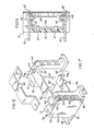
- Figs. 7 through 9 show another alternative embodiment of the current sensor of this invention which may be used with conductors having significantly greater cross-sectional shape such that a support at the opposite end of the loop becomes desirable.
- the current sensor CS as aforedescribed is shown in isometric at the left-hand end of this view.
- the strap 42 has been replaced by separate upper and lower ferrous straps 50 and 52, respectively, each of these straps being a flat member of a selectable predetermined length.
- a housing 2′ is provided at the right-hand ends of these straps 50 and 52. Housing 2′ is identical to housing 2, but contains only a ferrous connector strap 54 therein.
- Strap 54 is C-shaped, the vertical leg of which is attached to the central web 2c′ of housing 2′ by rivets 10′.
- the horizontal upper and lower legs of strap 54 contain pressed-in nuts 14′ within openings in the legs to provide upper and lower magnetic terminals for the housing 2′.
- a cover 34′ is secured to the housing by rivets 36′.
- Straps 50 and 52 are attached to the upper and lower magnetic terminals of the housing 2′ by screws 44′.
- the current sensor CS with a lower strap 52 attached thereto may be positioned adjacent the conductor and maneuvered to a position wherein the strap 52 may be attached to the lower magnetic terminal of the support housing 2′ and the two housings 2 and 2′ may then be installed to the mounting surface adjacent the conductor in which current is to be measured.
- the upper strap 50 may subsequently be attached to the magnetic terminals of housings 2 and 2′ to complete the magnetic loop.
- An alternate embodiment upper strap 60 is shown in Fig. 8 which may be utilized for conductors which additionally have a significant vertical dimension as well as a width dimension.
- the strap 60 may be formed to have a selectable predetermined vertical offset between the ends which are to be attached to the magnetic terminals of the two housings.
- a control circuit 70 for the current sensor CS is shown in Fig. 10.
- Control 70 is formed on circuit board 26 with the exception of magnetoresistive transducer 24 which is suspended therefrom by its wire leads.
- Transducer 24 essentially is a resistive bridge which is normally balanced at zero magnetic field. In the presence of biasing magnets 18 and 20 the field becomes unbalanced and produces a differential voltage which is proportional to the amount of field that transducer 24 senses between pole pieces 4 and 6.
- control circuit 70 will thus produce an output voltage which is proportional to the magnetic field and thus the current flow in conductor 46.
- the elements of control circuit 70 are schematically illustrated which, as previously mentioned, are physically disposed on circuit board 26 within housing 2.
- Control circuit 70 receives its power from a regulated voltage power supply at one of the terminals 28 such as terminal 28a provided by the host system incorporating sensor CS.
- Terminal 28a may be an upper terminal on section 2a of housing 2 and is interconnected to the +terminal of an op amp 106 through a 100 K resistor 108.
- the -input of op amp 106 is connected to ground through a 100 K resistor 110 and to the output terminal of op amp 106 through a 10 K feedback resistor 112.
- the output of op amp 106 is interconnected with terminal II of transducer 24 through a 380 ohm resistor 114.
- the +input of op ammp 106 is also interconnected to terminal II of transducer 24 through a 1 K resistor 116.
- Op amp 106 and resistors 108, 110, 112, 114 and 116 comprise a current source designated generally at 118 providing temperature compensation to the balance of circuit 70.
- Terminal IV of transducer 24 is connected to ground through a 100 K resistor 120 and to the -input trminal of an op amp 122 through a 120 K resistor 124.
- the +terminal of op amp 122 is connected to ground through a 100 K resistor 126.
- the output terminal of op amp 122 is interconnected to its -input terminal through a 540 K feedback resistor 128 and to the +input terminal of op amp 106 through a 540 K resistor 130.
- Op amp 122 and resistors 120, 124, 126, 128 and 130 provide additional temperature compensation and represent an option in control circuit 16. If such compensation is not required, those elements can be deleted and terminal IV of transducer 24 can be tied directly to ground as an alternative.
- Terminals II and IV of transducer 24 are interconnected by the fixed resistor portion of a 50 K potentiometer 132 acting as a voltage divider for providing zero field offset.
- the wiper of potentiometer 132 is interconnected to the +input terminal of an op amp 134 through a 247 K resistor 136.
- the +input terminal of op amp 134 is also interconnected to ground through a series combination of two 128 K resistors 138 and 140.
- Terminal I of transducer 24 is interconnected with the -input terminal of op amp 134 through a 10 K resistor 142 and terminal III of transducer 24 is interconnected with the -input terminal of op amp 134 through a 10 K resistor 146.
- the output terminal of op amp 134 is directly connected to a user accessible terminal 28b providing an analog voltage level proportional to sensed current.
- the output of op amp 134 is also interconnected to the -input thereof through a series combination of two 128 K resistors 148 and 150.
- the point of common connection between resistors 148 and 150 is interconnected to the point of common connection between resistors 138 and 140 by the fixed resistance portion of a potentiometer 152.
- the point of common connection between resistors 148 and 150 is also directly connected to the wiper of potentiometer 152.
- Op amp 134 and resistors 142, 146, 148 and 150 comprise a T-type amplifier designated by arrow 154 and resistors 138 and 140 with potentiometer 152 comprises a temperature comensation circuit designated generally 156.
- the output of op amp 134 is interconnected to the -input of an op amp 158 through a 10 K resistor 160.
- the +input of op amp 158 is connected to ground through a 11 K resistor 162.
- the output of op amp 158 is interconnected with the -input thereof through a 22 K feedback resistor 164.
- Op amp 158 and resistors 160, 162 and 164 comprise an inverting amplifier designated generally at 166.
- the output of amplifier 166 is interconnected to the -input of op amp 168 through a 10 K resistor 170 and to the -input of another op amp 172 through a second 10 K resistor 174.
- the +input terminals of both op amps 168 and 172 are connected to ground.
- the output of op amp 168 is connected to the base of a type 2N2222 transistor 176.
- the collector of transistor 176 is connected to a user accessible terminal 28c providing a current sink signal proportional to sensed current for EMI and RFI rejection purposes.
- the emitter of transistor 176 is interconnected to ground through a 10 ohm current limiting resistor 178.
- the emitter of transistor 176 is also interconnected to the -input of op amp 168 through the parallel combination of a IN4148 diode 180 and a 10 K resistor 182.
- Op amp 168 and its associated componentry constitutes a voltage controlled current sink circuit 184.
- the output of op amp 172 is interconnected to the base of a type 2W2907 transistor 186 and interconnected with a -input thereof through a series combination of a type lN4148 diode 188 and a parallel combination of a 10 K resistor 190 and a type lW4148 diode 192.
- a point of common connection between diode 188 and resistor 190 is connected to the emitter of transistor 186.
- the emitter of transistor 186 is also interconnected with the source of regulted voltage at terminal 28a through a 10 ohm current limiting resistor 194.
- Op amp 172 and its associated componentry function as a voltage controlled current source circuit designated generally 196 providing an output at the collector of transistor 186 to a user accessible terminal 28d a current source signal proportional to sensed current.
- the output terminal of op amp 134 is interconnected to the -input of an op amp 198 through a series combination of a 5 K resistor 200 and a 100 K resistor 202.
- the point of common connection between resistors 200 and 202 is interconnected to the +input terminal of op amp 198 through a 51 K resistor 204 and to ground through a 100 pico farad capacitor 206.
- the +input terminal of op amp 198 is connected to ground through a 51 K resistor 208.
- the output of op amp 198 is interconnected to the -input thereof through a 0.1 micro farad capacitor 210.
- the -input terminal of op amp 198 is interconnected to the collector of a type 2N2222 transistor 212 through a 51 K resistor 214.
- the emitter of transistor 212 is connected to ground.
- the output of op amp 198 is connected to the -input of another op amp 216.
- the +input terminal of op amp 216 is connected to ground through a series combination of a 50 K resistor 218 and a 10 K resistor 220.
- the point of common connection between resistors 218 and 220 is interconnected to the regulated voltage supply at terminal 28a through a 10 K resistor 222.
- the output terminal of op amp 216 is interconnected to the +input terminal thereof through a 2.2 M resistor 224 and is interconnected to the base of a type 2N2222 transistor 226 through a 3.3 K resistor 228.
- the collector of transistor 226 is connected to a user accessible terminal 28e through a 220 ohm current limiting resistor 230.
- the emitter of transistor 226 is connected to ground.
- a user accessible, or ground terminal 28f is provided as the upper terminal on section 26 of housing 2.
- the output terminal of op amp 216 is interconnected to the base of transistor 212 through a 5 K resistor 232.
- Op amps 198 and 216 as well as their associated componentry comprise a voltage control oscillator designated generally at 234.
- VCO 234 provides a modulated square wave output to transistor 226 which, with its associated components comprise an output circuit 236 providing isolation to control circuit 70.
- the output at terminal 28e provides a frequency modulated signal proportional to sensed current.
- Control circuit 70 thereby provides a plurality of user accessible outputs for extreme flexibility and application.
- a regulated voltage level in the range of 5 to 30 volts is contemplated.
Landscapes
- Physics & Mathematics (AREA)
- General Physics & Mathematics (AREA)
- Measuring Instrument Details And Bridges, And Automatic Balancing Devices (AREA)
Applications Claiming Priority (2)
| Application Number | Priority Date | Filing Date | Title |
|---|---|---|---|
| US61355 | 1987-06-11 | ||
| US07/061,355 US4791361A (en) | 1987-06-11 | 1987-06-11 | Current sensor for universal application |
Publications (2)
| Publication Number | Publication Date |
|---|---|
| EP0294635A2 true EP0294635A2 (fr) | 1988-12-14 |
| EP0294635A3 EP0294635A3 (fr) | 1990-09-05 |
Family
ID=22035266
Family Applications (1)
| Application Number | Title | Priority Date | Filing Date |
|---|---|---|---|
| EP19880108170 Withdrawn EP0294635A3 (fr) | 1987-06-11 | 1988-05-20 | Détecteur de courant pour l'application universel |
Country Status (2)
| Country | Link |
|---|---|
| US (1) | US4791361A (fr) |
| EP (1) | EP0294635A3 (fr) |
Cited By (1)
| Publication number | Priority date | Publication date | Assignee | Title |
|---|---|---|---|---|
| FR2625322A1 (fr) * | 1987-12-29 | 1989-06-30 | Eaton Corp | Capteur de courant a element magnetoresistif |
Families Citing this family (26)
| Publication number | Priority date | Publication date | Assignee | Title |
|---|---|---|---|---|
| CH674089A5 (fr) * | 1987-10-16 | 1990-04-30 | Lem Liaisons Electron Mec | |
| EP0338542B1 (fr) * | 1988-04-22 | 1993-08-04 | Matsushita Electric Industrial Co., Ltd. | Capteur de courant et/ou de tension pour un système de distribution |
| US4972140A (en) * | 1988-06-14 | 1990-11-20 | Stanley Electric Co., Ltd. | Current detection device and core for detection of magnetic flux |
| US5097202A (en) * | 1989-06-05 | 1992-03-17 | Sigma Instruments, Inc. | Faulted current indicators with improved signal to noise ratios |
| US5103163A (en) * | 1990-10-17 | 1992-04-07 | California Institute Of Technology | Current transducer |
| JPH04252934A (ja) * | 1991-01-29 | 1992-09-08 | Sanki Eng Kk | 多向流式遠心連続多段抽出装置 |
| US5221894A (en) * | 1992-03-02 | 1993-06-22 | Miller Electric Manufacturing Company | Weld current sensor |
| US5483161A (en) * | 1992-12-11 | 1996-01-09 | The United States Of America As Represented By The Secretary Of Commerce | Faraday effect continuous circuit flux concentrating magnetic field sensor |
| US6114847A (en) * | 1995-10-04 | 2000-09-05 | Johnson; Darrell | Connectionless signal detection device for conductive cables |
| US7158012B2 (en) | 1996-11-01 | 2007-01-02 | Foster-Miller, Inc. | Non-invasive powerline communications system |
| US6963195B1 (en) * | 1997-08-15 | 2005-11-08 | General Electric Company | Apparatus for sensing current |
| US6677743B1 (en) * | 1999-03-05 | 2004-01-13 | Foster-Miller, Inc. | High voltage powerline sensor with a plurality of voltage sensing devices |
| US7902854B2 (en) * | 2003-07-25 | 2011-03-08 | Power Measurement, Ltd. | Body capacitance electric field powered device for high voltage lines |
| US7282944B2 (en) * | 2003-07-25 | 2007-10-16 | Power Measurement, Ltd. | Body capacitance electric field powered device for high voltage lines |
| US7265533B2 (en) * | 2004-06-15 | 2007-09-04 | Power Measurement Ltd. | Non-intrusive power monitor |
| US20050288877A1 (en) * | 2004-06-25 | 2005-12-29 | Power Measurement Ltd., | Method and apparatus for instrument transformer reclassification |
| US7337080B2 (en) * | 2004-06-25 | 2008-02-26 | Power Measurement, Ltd. | Method and apparatus for instrument transformer reclassification |
| JP5222542B2 (ja) * | 2007-12-07 | 2013-06-26 | 矢崎総業株式会社 | 電流センサ |
| MX2010001276A (es) * | 2009-01-30 | 2011-01-10 | Elster Solutions Llc | Metodo y aparato para medir la salida de corriente de transformadores de energia de distribucion de bajo voltaje montados sobre cojinete. |
| CH705027A1 (de) * | 2011-05-30 | 2012-11-30 | Melexis Technologies Nv | Vorrichtung zur Messung eines durch ein elektrisches Kabel fliessenden Stroms. |
| JP2013148512A (ja) * | 2012-01-20 | 2013-08-01 | Aisin Seiki Co Ltd | 電流センサ |
| US9230765B2 (en) * | 2012-11-02 | 2016-01-05 | Rockwell Automation Technologies, Inc. | Modular overload relay assembly with mechanically isolated connector |
| DE102016101409A1 (de) * | 2016-01-27 | 2017-07-27 | Phoenix Contact Gmbh & Co. Kg | An eine Tragschiene ansetzbares Gehäuse zum Aufnehmen einer Elektronikbaugruppe |
| US10365696B1 (en) * | 2018-09-27 | 2019-07-30 | Moxa Inc. | Industrial input/output device with movable connector |
| CN111323639B (zh) * | 2020-03-27 | 2022-06-24 | 江苏多维科技有限公司 | 一种基于磁探头的电流测量装置及测量方法 |
| CN112305295B (zh) * | 2020-11-11 | 2024-07-09 | 江苏常荣电器股份有限公司 | 一种复合电流传感器 |
Family Cites Families (6)
| Publication number | Priority date | Publication date | Assignee | Title |
|---|---|---|---|---|
| DE521886C (de) * | 1929-09-15 | 1931-03-27 | Koch & Sterzel Akt Ges | Verfahren zum Herumlegen eines Ringstromwandlers um einen Leiter, insbesondere mit unzugaenglichen Enden |
| US3405355A (en) * | 1965-02-26 | 1968-10-08 | Navy Usa | Thin film magnetoresistance magnetometer having a current path etched at an angle tothe axes of magnetization |
| DE1616047B1 (de) * | 1967-07-01 | 1970-06-18 | Siemens Ag | Gleichstromwandler mit einer Brueckenschaltung mit vormagnetisierten Feldplatten |
| US3693085A (en) * | 1971-07-15 | 1972-09-19 | Gen Motors Corp | System for calibrated high level current measurement using a magnetic field responsive transistor |
| US4414543A (en) * | 1980-09-25 | 1983-11-08 | Schweitzer Edmund O Jun | Ground fault indicator |
| DD237929A1 (de) * | 1985-05-31 | 1986-07-30 | Transform Roentgen Matern Veb | Umbaustromwandler |
-
1987
- 1987-06-11 US US07/061,355 patent/US4791361A/en not_active Expired - Fee Related
-
1988
- 1988-05-20 EP EP19880108170 patent/EP0294635A3/fr not_active Withdrawn
Cited By (1)
| Publication number | Priority date | Publication date | Assignee | Title |
|---|---|---|---|---|
| FR2625322A1 (fr) * | 1987-12-29 | 1989-06-30 | Eaton Corp | Capteur de courant a element magnetoresistif |
Also Published As
| Publication number | Publication date |
|---|---|
| US4791361A (en) | 1988-12-13 |
| EP0294635A3 (fr) | 1990-09-05 |
Similar Documents
| Publication | Publication Date | Title |
|---|---|---|
| EP0294635A2 (fr) | Détecteur de courant pour l'application universel | |
| US4841235A (en) | MRS current sensor | |
| US4240059A (en) | Current divider for a current sensing transducer | |
| US5343143A (en) | Shielded current sensing device for a watthour meter | |
| US4939448A (en) | Electric current sensing device of the magnetic field compensationtype | |
| KR100450012B1 (ko) | 전류 센서 | |
| US4939449A (en) | Electric current sensing device of the magnetic field compensation type | |
| US6472878B1 (en) | Current measuring element with a hall sensor | |
| US4623266A (en) | Cold junction compensation for thermocouple | |
| US4857837A (en) | Magneto resistive current sensor with improved fidelity | |
| US7977934B2 (en) | High bandwidth open-loop current sensor | |
| US5642041A (en) | Alternating current sensor employing parallel plates and having high dynamic range and accuracy | |
| EP1037057B1 (fr) | Capteur de courant électrique | |
| JPH0483175A (ja) | 電流検出装置 | |
| KR19980080610A (ko) | 전류 센서 | |
| EP1467214A2 (fr) | Capteur de courant et unité de détection de courant l'utilisant | |
| US4947108A (en) | Electric current sensing device | |
| US4864223A (en) | Measuring transformer to measure the current flowing in an electric conductor | |
| US5701073A (en) | Direct current measuring apparatus and method employing flux diversion | |
| US5436557A (en) | Current sensor which is attachable to an external object by retention between the external object and an electrical conductor | |
| US5233872A (en) | Acceleration sensor and acceleration sensing system | |
| US2776404A (en) | Magnetometer | |
| CN109799380B (zh) | 一种集成式电流传感器及其封装方法 | |
| EP4471436B1 (fr) | Transducteur de courant à boucle ouverte | |
| US6351115B1 (en) | Low profile laminated shunt |
Legal Events
| Date | Code | Title | Description |
|---|---|---|---|
| PUAI | Public reference made under article 153(3) epc to a published international application that has entered the european phase |
Free format text: ORIGINAL CODE: 0009012 |
|
| AK | Designated contracting states |
Kind code of ref document: A2 Designated state(s): DE FR |
|
| PUAL | Search report despatched |
Free format text: ORIGINAL CODE: 0009013 |
|
| AK | Designated contracting states |
Kind code of ref document: A3 Designated state(s): DE FR |
|
| 17P | Request for examination filed |
Effective date: 19910102 |
|
| 17Q | First examination report despatched |
Effective date: 19921013 |
|
| STAA | Information on the status of an ep patent application or granted ep patent |
Free format text: STATUS: THE APPLICATION IS DEEMED TO BE WITHDRAWN |
|
| 18D | Application deemed to be withdrawn |
Effective date: 19930224 |