EP0294136A2 - Heizeinheit mit einem thermochromen Temperaturanzeiger - Google Patents
Heizeinheit mit einem thermochromen Temperaturanzeiger Download PDFInfo
- Publication number
- EP0294136A2 EP0294136A2 EP88304920A EP88304920A EP0294136A2 EP 0294136 A2 EP0294136 A2 EP 0294136A2 EP 88304920 A EP88304920 A EP 88304920A EP 88304920 A EP88304920 A EP 88304920A EP 0294136 A2 EP0294136 A2 EP 0294136A2
- Authority
- EP
- European Patent Office
- Prior art keywords
- indicator
- track
- substrate
- thermochromic
- heating unit
- Prior art date
- Legal status (The legal status is an assumption and is not a legal conclusion. Google has not performed a legal analysis and makes no representation as to the accuracy of the status listed.)
- Withdrawn
Links
Images

Classifications
-
- H—ELECTRICITY
- H05—ELECTRIC TECHNIQUES NOT OTHERWISE PROVIDED FOR
- H05B—ELECTRIC HEATING; ELECTRIC LIGHT SOURCES NOT OTHERWISE PROVIDED FOR; CIRCUIT ARRANGEMENTS FOR ELECTRIC LIGHT SOURCES, IN GENERAL
- H05B3/00—Ohmic-resistance heating
- H05B3/20—Heating elements having extended surface area substantially in a two-dimensional [2D] plane, e.g. plate-heater
- H05B3/22—Heating elements having extended surface area substantially in a two-dimensional [2D] plane, e.g. plate-heater non-flexible
- H05B3/26—Heating elements having extended surface area substantially in a two-dimensional [2D] plane, e.g. plate-heater non-flexible heating conductor mounted on insulating base
-
- B—PERFORMING OPERATIONS; TRANSPORTING
- B60—VEHICLES IN GENERAL
- B60H—ARRANGEMENTS OF HEATING, COOLING, VENTILATING OR OTHER AIR-TREATING DEVICES SPECIALLY ADAPTED FOR PASSENGER OR GOODS SPACES OF VEHICLES
- B60H1/00—Heating, cooling or ventilating devices
- B60H1/22—Heating, cooling or ventilating devices the heat source being other than the propulsion plant
- B60H1/2215—Heating, cooling or ventilating devices the heat source being other than the propulsion plant the heat being derived from electric heaters
- B60H1/2227—Electric heaters incorporated in vehicle trim components, e.g. panels or linings
-
- H—ELECTRICITY
- H05—ELECTRIC TECHNIQUES NOT OTHERWISE PROVIDED FOR
- H05B—ELECTRIC HEATING; ELECTRIC LIGHT SOURCES NOT OTHERWISE PROVIDED FOR; CIRCUIT ARRANGEMENTS FOR ELECTRIC LIGHT SOURCES, IN GENERAL
- H05B3/00—Ohmic-resistance heating
- H05B3/68—Heating arrangements specially adapted for cooking plates or analogous hot-plates
- H05B3/74—Non-metallic plates, e.g. vitroceramic, ceramic or glassceramic hobs, also including power or control circuits
- H05B3/748—Resistive heating elements, i.e. heating elements exposed to the air, e.g. coil wire heater
-
- H—ELECTRICITY
- H05—ELECTRIC TECHNIQUES NOT OTHERWISE PROVIDED FOR
- H05B—ELECTRIC HEATING; ELECTRIC LIGHT SOURCES NOT OTHERWISE PROVIDED FOR; CIRCUIT ARRANGEMENTS FOR ELECTRIC LIGHT SOURCES, IN GENERAL
- H05B2203/00—Aspects relating to Ohmic resistive heating covered by group H05B3/00
- H05B2203/002—Heaters using a particular layout for the resistive material or resistive elements
-
- H—ELECTRICITY
- H05—ELECTRIC TECHNIQUES NOT OTHERWISE PROVIDED FOR
- H05B—ELECTRIC HEATING; ELECTRIC LIGHT SOURCES NOT OTHERWISE PROVIDED FOR; CIRCUIT ARRANGEMENTS FOR ELECTRIC LIGHT SOURCES, IN GENERAL
- H05B2203/00—Aspects relating to Ohmic resistive heating covered by group H05B3/00
- H05B2203/013—Heaters using resistive films or coatings
-
- H—ELECTRICITY
- H05—ELECTRIC TECHNIQUES NOT OTHERWISE PROVIDED FOR
- H05B—ELECTRIC HEATING; ELECTRIC LIGHT SOURCES NOT OTHERWISE PROVIDED FOR; CIRCUIT ARRANGEMENTS FOR ELECTRIC LIGHT SOURCES, IN GENERAL
- H05B2203/00—Aspects relating to Ohmic resistive heating covered by group H05B3/00
- H05B2203/017—Manufacturing methods or apparatus for heaters
-
- H—ELECTRICITY
- H05—ELECTRIC TECHNIQUES NOT OTHERWISE PROVIDED FOR
- H05B—ELECTRIC HEATING; ELECTRIC LIGHT SOURCES NOT OTHERWISE PROVIDED FOR; CIRCUIT ARRANGEMENTS FOR ELECTRIC LIGHT SOURCES, IN GENERAL
- H05B2213/00—Aspects relating both to resistive heating and to induction heating, covered by H05B3/00 and H05B6/00
- H05B2213/04—Heating plates with overheat protection means
Definitions
- the present invention relates to a heating unit comprising a thermochromic temperature indicator, and it relates especially, although not exclusively, to such an indicator as may be used to give a visual warning that a surface of the heating unit which is being, or has recently been, heated is too hot to touch.
- thermochromic indicators for example on the hobs of domestic cookers with glass ceramic cooktops, but although many potentially useful thermochromic materials are known, difficulties arise in providing the necessary visual indication with sufficient clarity and temperature stability for use in demanding environments.
- Thermochromic materials suitable for applications as temperature indicators include organic materials with good temperature sensitivity but poor temperature stability and a range of less sensitive but more stable inorganic materials, including those described and claimed in our copending European Patent Application claiming priority from GB 8709051. Many of these materials are appropriate for applications to any of a number of heated devices, the material selected in each case being governed by the operating temperature of the device in question.
- Thermochromic temperature indicators are often applied with temperature sensitive material defining a shape or word on a similarly coloured non-thermochromic background. When heated, the defined pattern (possibly 'hot' or 'on') stands out from the background as an indication of the elevated temperature. This configuration works very well for low temperature indications but its high temperature use is limited by the non-availability of temperature stable, colour-matched, non-thermochromic materials with sufficient colour strength.
- a temperature indicator displaying a defined pattern is prepared without the need for a non-thermochromic background by juxtaposing a thick film track and a thermochromic layer.
- the track is printed on a suitable substrate, e.g. a glass ceramic cooktop, so as to conform to the desired pattern and a suitable thermochromic material is applied to the substrate so as to cover the track pattern and also an area in excess of that occupied by the track pattern.
- a heating unit comprising a thermochromic temperature indicator on a substrate and a heating element; the indicator comprising a thick film electrically resistive indicator track having a defined pattern printed on the substrate, a layer of a thermochromic material applied to the substrate so as to cover and surround the defined pattern and means for responding to passage of current in said heating element by generating a current in said indicator track.
- thermochromic material covering and immediately above the indicator track to become hotter than, and hence be of a different colour from, the thermochromic material outside the area occupied by the indicator track.
- a colour-changed area of the desired shape i.e. the pattern of the indicator track
- the colour change is reversed at a rate determined by the materials and configuration chosen.
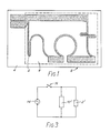
- Figure 1 shows a suitable indicator track design with the defined pattern showing the (English) word 'hot'.
- the indicator track is an electrically resistive thick film track 2 and is printed on a substrate 4.
- the substrate used preferably has very poor lateral thermal conductivity to prevent excessive spreading of the heat and corresponding blurring of the pattern. Glass or glass ceramic is suitable in this respect.
- a layer of a suitable thermochromic material (indicated by dotted lines and referenced by the number 6) is applied to the substrate 4 so as to cover and surround the indicator track 2. The whole forms an indicator unit 8.
- a heating element shown in Figure 2, comprises an electrically resistive thick film track 10 on a substrate 12.
- the track is overglazed with a glass ceramic material to protect the track and to allow high temperature stable operation.
- the unit so produced can be mounted closely adjacent the underside of a glass ceramic cooktop to provide a heated area on the cooktop.
- the indicator unit 8 associated with a heating element is provided in a position to be readily visible to a user of the heating element. Suitable positions include a position adjacent to the heated area (for example, on a ceramic cooker hob just outside the hotplate area) or a position completely detached from the heated area, possibly on a control panel.
- FIG. 3 A suitable but simple electrical circuit for connecting the indicator unit 8 and its associated heating element is shown in Figure 3.
- the resistance of the heating track is represented by the resistance 10′ and that of the indicator track by the resistance 2′.
- the two tracks 10, 2 are connected in parallel across a power supply 14. When the heating track 10 is switched on, at a switch 16, current flows both in the heating track 10 and in the indicator track 2.
- any electrical circuit can be used which includes the essential feature that passage of current in the heating track will cause a current to be generated in the indicator track.
- current also passes through the indicator track so that the indicator track heats up. Accordingly, when the indicator track is hot, this indicates that the heating track is also hot.
- thermochromic material covering and immediately above it becomes hotter than the surrounding thermochromic material. This produces a colour contrast between the hotter thermochromic material immediately above the indicator track and the cooler thermochromic material surrounding the track and so a colour-changed area having the defined pattern of the indicator track becomes visible.
- the heating track and indicator track cool down at a rate determined by the materials of which they and their respective substrates are made and on the respective configurations used.
- the thermal mass of the substrate 4 on which the indicator track 2 is applied it is possible to ensure that the coloured pattern remains visible for at least as long as the heated area in question is at a 'dangerous' temperature.
- the heater track could be part of a thick film or any other type of heating element or connected as a separate circuit not necessarily operating at mains voltage.
- the indicator could be adjacent to the heated area (for example, on a ceramic cooker hob just outside the hotplate area) or completely detached from the heated area, possibly on a control panel.
- thermochromic background colour offers several other benefits.
- the invention offers several other benefits.
- the thermal mass of the substrate it is possible to ensure that the coloured pattern remains visible for at least as long as the heated area in question is at a 'dangerous' temperature.
- the voltage applied to the thick film track can be selected so that the indicator operates at a different temperature to that of the heater device to which it is attached. This increases the choice of thermochromic materials which can be used for any given application, even allowing the use of sensitive low temperature materials with high temperature devices. Modifications to this embodiment within the scope of the invention will be apparent to those skilled in the art.
Landscapes
- Engineering & Computer Science (AREA)
- Physics & Mathematics (AREA)
- Thermal Sciences (AREA)
- Mechanical Engineering (AREA)
- Chemical & Material Sciences (AREA)
- Ceramic Engineering (AREA)
- Measuring Temperature Or Quantity Of Heat (AREA)
- Heat Sensitive Colour Forming Recording (AREA)
- Surface Treatment Of Glass (AREA)
- Resistance Heating (AREA)
Applications Claiming Priority (2)
| Application Number | Priority Date | Filing Date | Title |
|---|---|---|---|
| GB878713103A GB8713103D0 (en) | 1987-06-04 | 1987-06-04 | Thermochromic temperature indicators |
| GB8713103 | 1987-06-04 |
Publications (2)
| Publication Number | Publication Date |
|---|---|
| EP0294136A2 true EP0294136A2 (de) | 1988-12-07 |
| EP0294136A3 EP0294136A3 (de) | 1990-12-05 |
Family
ID=10618375
Family Applications (1)
| Application Number | Title | Priority Date | Filing Date |
|---|---|---|---|
| EP19880304920 Withdrawn EP0294136A3 (de) | 1987-06-04 | 1988-05-31 | Heizeinheit mit einem thermochromen Temperaturanzeiger |
Country Status (3)
| Country | Link |
|---|---|
| EP (1) | EP0294136A3 (de) |
| JP (1) | JPS646392A (de) |
| GB (1) | GB8713103D0 (de) |
Cited By (9)
| Publication number | Priority date | Publication date | Assignee | Title |
|---|---|---|---|---|
| GB2238216A (en) * | 1989-11-18 | 1991-05-22 | Electrolux Components Ltd | Lamp and thick film heated ceramic hob plate |
| DE9311061U1 (de) * | 1993-07-23 | 1993-10-28 | Ech Elektrochemie Halle Gmbh, 06120 Halle | Vorrichtung zur Thermostatierung von gaschromatographischen Trennsäulen |
| DE4317040A1 (de) * | 1993-05-21 | 1994-04-28 | Schott Glaswerke | Glaskeramikkochfeld mit wenigstens einer Kochzone und einer zugeordneten Anzeigeeinrichtung |
| USD369516S (en) | 1994-12-23 | 1996-05-07 | Ceramaspeed Limited | Radiant stove heater |
| WO1998007345A1 (en) * | 1996-08-16 | 1998-02-26 | Monty Lawrence P | Thermochromic handheld hair curling iron |
| AT410879B (de) * | 2001-09-10 | 2003-08-25 | Vaillant Gmbh | Elektro-warmwasserspeicher |
| WO2004113459A3 (en) * | 2003-06-18 | 2005-03-31 | Royal College Of Art | Method of producing patterns in concrete and other building materials |
| WO2016089923A1 (en) * | 2014-12-01 | 2016-06-09 | Chromatic Technologies, Inc. | Thermochromic efficiency indicator |
| US20180310363A1 (en) * | 2017-04-21 | 2018-10-25 | Robert Varnedoe | Color-changing heat mats |
Family Cites Families (2)
| Publication number | Priority date | Publication date | Assignee | Title |
|---|---|---|---|---|
| US3323241A (en) * | 1965-10-24 | 1967-06-06 | Texas Instruments Inc | Passive information displays |
| US3781522A (en) * | 1972-03-27 | 1973-12-25 | Gen Electric | Thermochromic surface heating apparatus |
-
1987
- 1987-06-04 GB GB878713103A patent/GB8713103D0/en active Pending
-
1988
- 1988-05-31 EP EP19880304920 patent/EP0294136A3/de not_active Withdrawn
- 1988-06-03 JP JP63135794A patent/JPS646392A/ja active Pending
Cited By (10)
| Publication number | Priority date | Publication date | Assignee | Title |
|---|---|---|---|---|
| GB2238216A (en) * | 1989-11-18 | 1991-05-22 | Electrolux Components Ltd | Lamp and thick film heated ceramic hob plate |
| DE4317040A1 (de) * | 1993-05-21 | 1994-04-28 | Schott Glaswerke | Glaskeramikkochfeld mit wenigstens einer Kochzone und einer zugeordneten Anzeigeeinrichtung |
| DE9311061U1 (de) * | 1993-07-23 | 1993-10-28 | Ech Elektrochemie Halle Gmbh, 06120 Halle | Vorrichtung zur Thermostatierung von gaschromatographischen Trennsäulen |
| USD369516S (en) | 1994-12-23 | 1996-05-07 | Ceramaspeed Limited | Radiant stove heater |
| WO1998007345A1 (en) * | 1996-08-16 | 1998-02-26 | Monty Lawrence P | Thermochromic handheld hair curling iron |
| AT410879B (de) * | 2001-09-10 | 2003-08-25 | Vaillant Gmbh | Elektro-warmwasserspeicher |
| WO2004113459A3 (en) * | 2003-06-18 | 2005-03-31 | Royal College Of Art | Method of producing patterns in concrete and other building materials |
| WO2016089923A1 (en) * | 2014-12-01 | 2016-06-09 | Chromatic Technologies, Inc. | Thermochromic efficiency indicator |
| US10113920B2 (en) | 2014-12-01 | 2018-10-30 | Chromatic Technologies, Inc. | Thermochromic efficiency indicator |
| US20180310363A1 (en) * | 2017-04-21 | 2018-10-25 | Robert Varnedoe | Color-changing heat mats |
Also Published As
| Publication number | Publication date |
|---|---|
| GB8713103D0 (en) | 1987-07-08 |
| EP0294136A3 (de) | 1990-12-05 |
| JPS646392A (en) | 1989-01-10 |
Similar Documents
| Publication | Publication Date | Title |
|---|---|---|
| EP0286217B1 (de) | Bahnen aus starkem Film mit elektrischem Widerstand | |
| CA2086861C (en) | Radiant heater having multiple heating zones | |
| US3612826A (en) | Surface temperature indicator light for ceramic top infrared radiant range | |
| US6555793B2 (en) | Advanced radiant electric heater | |
| US3624352A (en) | Ceramic top range surface temperature cut-off thermostatic device | |
| US4518850A (en) | Electric cooker having temperature warning means | |
| US5283412A (en) | Temperature-measuring device for an induction-type cooking appliance and appliance having such a device | |
| EP0294136A2 (de) | Heizeinheit mit einem thermochromen Temperaturanzeiger | |
| JPH0658554A (ja) | ガラスセラミックもしくは類似の材料から作製された加熱面における異常熱応力状態を指示する方法及び装置 | |
| CA2388774A1 (en) | Cooktop control | |
| SE8104801L (sv) | Varningsanordning for elektriska kokapparater | |
| ATE9127T1 (de) | Glaskeramik-kochgeraet. | |
| KR20200021820A (ko) | 전기 히터 | |
| GB2125537A (en) | Cooker hob | |
| DE60305464D1 (de) | Elektrische heizbaugruppe | |
| CA2439606A1 (en) | Ceramic hotplate consisting of a glass ceramic plate | |
| US3848111A (en) | Electrical heating unit | |
| GB2193617A (en) | Radiant heating means | |
| GB2138659A (en) | Glass Ceramic Hob including Temperature Sensor | |
| GB2102170A (en) | A residual heat display for an electric cooker | |
| GB2100883A (en) | An arrangement for the determination of temperature in cooking apparatus | |
| US6794621B1 (en) | Cook top status indicator | |
| SE447506B (sv) | Signalanordning for kokplattor | |
| CA1198762A (en) | Circuit arrangement for heating elements in cooking surfaces of ranges | |
| KR100298104B1 (ko) | 온도표시기를구비한열효과장치 |
Legal Events
| Date | Code | Title | Description |
|---|---|---|---|
| PUAI | Public reference made under article 153(3) epc to a published international application that has entered the european phase |
Free format text: ORIGINAL CODE: 0009012 |
|
| AK | Designated contracting states |
Kind code of ref document: A2 Designated state(s): AT BE CH DE ES FR GB GR IT LI LU NL SE |
|
| PUAL | Search report despatched |
Free format text: ORIGINAL CODE: 0009013 |
|
| AK | Designated contracting states |
Kind code of ref document: A3 Designated state(s): AT BE CH DE ES FR GB GR IT LI LU NL SE |
|
| STAA | Information on the status of an ep patent application or granted ep patent |
Free format text: STATUS: THE APPLICATION IS DEEMED TO BE WITHDRAWN |
|
| 18D | Application deemed to be withdrawn |
Effective date: 19900601 |