EP0293356A1 - Additional retractable body hygiene device in a toilet at the traditional type - Google Patents
Additional retractable body hygiene device in a toilet at the traditional type Download PDFInfo
- Publication number
- EP0293356A1 EP0293356A1 EP88870093A EP88870093A EP0293356A1 EP 0293356 A1 EP0293356 A1 EP 0293356A1 EP 88870093 A EP88870093 A EP 88870093A EP 88870093 A EP88870093 A EP 88870093A EP 0293356 A1 EP0293356 A1 EP 0293356A1
- Authority
- EP
- European Patent Office
- Prior art keywords
- water
- bowl
- figures
- pressure
- toilet
- Prior art date
- Legal status (The legal status is an assumption and is not a legal conclusion. Google has not performed a legal analysis and makes no representation as to the accuracy of the status listed.)
- Withdrawn
Links
Images


Classifications
-
- E—FIXED CONSTRUCTIONS
- E03—WATER SUPPLY; SEWERAGE
- E03D—WATER-CLOSETS OR URINALS WITH FLUSHING DEVICES; FLUSHING VALVES THEREFOR
- E03D9/00—Sanitary or other accessories for lavatories ; Devices for cleaning or disinfecting the toilet room or the toilet bowl; Devices for eliminating smells
- E03D9/08—Devices in the bowl producing upwardly-directed sprays; Modifications of the bowl for use with such devices ; Bidets; Combinations of bowls with urinals or bidets; Hot-air or other devices mounted in or on the bowl, urinal or bidet for cleaning or disinfecting
Definitions
- the device was designed to be installed on a traditional type of toilet, called "English", it consists of a bowl, a flush.
- the bowl is supplied with flush water which is distributed inside and an outlet for water and waste disposal.
- the device was designed with a diameter and a length such that it can be installed inside the water distribution system in the bowl.
- the device consists of a retractable shower system with telescopic movement.
- the device consists of two metal tubes fitted together with a spiral spring that controls the relative movement of two tubes
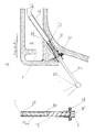
- FIG. 10 The device is shown by 10 drawings, in page 8 figure A is a front cutout, figure B a side cutout, figures C and D horizontal cutouts, in page 9 figures E and H show the mechanism and wedging system, on page 10 figure d is a front cutout, figure f a side cutout figures e and g of the horizontal cutouts.
- WC installations are known in which the human washing operation is carried out using a device for preheating preheated water which is moved from a rest position to an operating position as noted in Belgian patent number 767443 of 25/3/1971, Belgian patent number 800.078 of 25/5/1973 and European patent number EP 00011077 of 21/2/1979.
- the present mechanism is part of the trend towards simplification and cost reduction which has characterized the evolution of the technique as well as the quest for simplicity and above all, maximum hygiene and safety.
- the device consists of four parts: the support tube, the shower tube, the spiral spring and the cool water supply system and the heat source.
- the support tube is housed entirely housed inside the water inlet of the bowl.
- One end is connected to the water supply system (page 10, numbers 14 to 60 figures d, e, f, g), followed by a straight body (page 8, figures A, B, C, D), and the other end is provided with a piece wedged in the water pipe of the WC (number 12 figures A, B, D, D, H).
- This wedge is capable of withstanding alternative forces in the opposite direction caused by the starting and stopping of the mechanism (number 12, figures B, E, H) allowing the shower to be completely hidden when it is out of operation. (number 1 figures E, H).
- the shower tube is fitted into the support tube where it moves telescopically (number 2 fig; E, H): -it comes out under water pressure when the mechanism is put into operation (number 1, figures A to E). - it enters under the pressure of a spiral spring when the mechanism is deactivated (number & figure h)
- One end of the shower hose is provided with a plastic valve (number 14 figures F, H) it continues with a straight tube (number 2 figures E, H), the other end is provided with a shower (number 1 figures A and H) provided with a longitudinal perforation (number 15 figures C, D, E, H).
- the shower end disappears entirely in the support tube (number 1 and 2 in figure H) when the device is at rest, which disappears behind the water supply system of the bowl (number 3 and 11 in figure E). This particularity of the device makes it possible to distinguish it from other devices with similar uses already patented and that determines a manifest superiority in the field of hygiene.
- the supply system links the shower support tube (page 9 number 3 figure E) with the water distribution network (page 10 number 14 figures d, e) and controls the water pressure by a tap (page 8, number 7 figures C and D).
- the feeding system consists of: - a tap (page 10, number 20 figures d, e; number 7 figures A, B, C, D). - the pipes (page 10, numbers 11,11a, 13,15,17, 60 of figures d, e, f, g).
- the water heating system consists of a tank heated by a resistor supplied with rectified current of 12 volts 3 amps by a transformer located outside the bathroom (page 10 numbers 54,55 and 59 of the figures d , e) whose temperature is controlled by a by a thermostat (number 54 figures d, e), working with the conductor (page 10, number 55 figure d, e).
Abstract
Description
Le dispositif a été conçu pour être installé sur un W.C. de type traditionnel, dit "anglais", celui-ci se compose d'un cuvette, d'une chasse d'eau. La cuvette est alimenté avec l'eau de la chasse qui est distribué a l'intérieur et une sortie d'évacuation de l'eau et des déchets.The device was designed to be installed on a traditional type of toilet, called "English", it consists of a bowl, a flush. The bowl is supplied with flush water which is distributed inside and an outlet for water and waste disposal.
Le dispositif a été conçu avec un diamètre et une longueur tels permettant l'installation à l'intérieur du système de distribution d'eau dans la cuvette.The device was designed with a diameter and a length such that it can be installed inside the water distribution system in the bowl.
Le dispositif consiste dans un système de douche escamotable à déplacement téléscopique. Le dispositif se compose de deux tubes métalliques emboîtés avec un ressort en spirale que controlle le déplacement relatif de deux tubesThe device consists of a retractable shower system with telescopic movement. The device consists of two metal tubes fitted together with a spiral spring that controls the relative movement of two tubes
Le dispositif est montré par 10 dessins, dans la page 8 le figure A est une découpe frontale, la figure B une découpe latérale, les figures C et D des découpes horizontales, dans la page 9 les figures E et H montrent le mécanisme et le système de calage, dans la page 10 la figure d est une découpe frontale,la figure f une découpe latérale les figures é et g des découpes horizontales.The device is shown by 10 drawings, in
Dans l'état actuel de la technique on connaît des installations de W.C. dans lesquelles on réalise l'opération de lavage humain a l'aide d'un dispositif de proyection d'eau préchauffé qu'on fait déplacer d'une position de repos à une position de fonctionnement comme le remarque le brevet belge numéro 767443 du 25/3/1971, le brevet belge numéro 800.078 du 25/5/1973 et le brevet européen numéro EP 00011077 du 21/2/1979.In the current state of the art, WC installations are known in which the human washing operation is carried out using a device for preheating preheated water which is moved from a rest position to an operating position as noted in Belgian patent number 767443 of 25/3/1971, Belgian patent number 800.078 of 25/5/1973 and European patent number EP 00011077 of 21/2/1979.
Le présent mecanisme s'inscrit dans la tendance vers la simplification et réduction des coûts qui a caracterisé l'evolution de la technique ainsi que la recherche de la simplicité et surtout, l'hygiène et la securité maximales.The present mechanism is part of the trend towards simplification and cost reduction which has characterized the evolution of the technique as well as the quest for simplicity and above all, maximum hygiene and safety.
Le dispositif se compose de quatre parties: le tube support, le tube douche, le ressort en spirale et le système d'alimentation en eau fraoide et la source de chaleur.The device consists of four parts: the support tube, the shower tube, the spiral spring and the cool water supply system and the heat source.
Il s'agit d'un tube métallique qui contient les autres pièces du mécanisme. Le tube support est logé entièrement logé à l'intérieur de l'entrée d'eau de la cuvette. (Voir figures A, B,D,E, feulle 8 numéro 3).
Une extremité est connecté au système d'alimentation d'eau (page 10, numéros 14 à 60 figures d,e,f,g), suivi d'un corps droit (page 8, figures A,B,C,D), et l'autre bout est pourvu d'une pièce calée dans la canalisation d'eau du W.C. (numéro 12 figures A, B, D, D,H).
Cette cale est capable de résister aux forces alternatives en sens opposé provoqués par la mise en route et l'arrêt du mecanisme (numéro 12, figures B,E,H) permettant de cacher entièrement la douche quand elle est hors fonctionnement. (numéro 1 figures E,H).It is a metal tube that contains the other parts of the mechanism. The support tube is housed entirely housed inside the water inlet of the bowl. (See figures A, B, D, E,
One end is connected to the water supply system (
This wedge is capable of withstanding alternative forces in the opposite direction caused by the starting and stopping of the mechanism (
Le tube douche est emboîté dans le tube support où il se deplace de façon téléscopique (numéro 2 fig;E,H):
-il sort sous la pression de l'eau au moment de la mise en opération de mécanisme (numéro 1, figures A à E).
- il rentre sous la pression de ressort en spirale au moment de la mise hors fonctionnement du mécanisme (numero & figure h)The shower tube is fitted into the support tube where it moves telescopically (
-it comes out under water pressure when the mechanism is put into operation (
- it enters under the pressure of a spiral spring when the mechanism is deactivated (number & figure h)
Une extremité du tuyau douche est pourvue d'une soupape plastique (numéro 14 figures F,H) il continue par un tube droit (numéro 2 figures E,H), l'autre extrémité est pourvue d'une douche (numéro 1 figures A et H) munie d'une perforation longitudinale (numéro 15 figures C,D,E,H).
L'extremité douche disparaît entièrement dans le tube support (numéro 1 et 2 figure H) au moment du repos du dispositif, qui lui lui disparaît derière le système d'alimentation en eau de la cuvette (numéro 3 et 11 figure E). Cette particularité du du dispositif permet de le distinguer des autres dispositifs aux usages similaires déjà brévetés et que determine une supériorité manifeste dans le domaine de l'hygiène.One end of the shower hose is provided with a plastic valve (
The shower end disappears entirely in the support tube (
Il est placé entre les deux tuyau décrits,entièrement caché par le tube support (numéro 16 figure H). Une extremité se trouve calée par un pli à l'extremité du tube support (numéro 12 figure H) et l'autre par la soupape plastique du tube douche (numéro 12 figures E,H). Le ressort met en place le tube douche au moment de l'arrêt du fonctionnement du méchanisme (voir ressort figures E,H). La properté et le bon fonctionnement dumécanisme est assuré par le flux d'eau en provenance de la chasse et de la doucheIt is placed between the two described pipes, completely hidden by the support tube (
Le système d'alimentation lie le tube support de la douche (page 9 numéro 3 figure E) avec le réseau de distribution d'aue (page 10 numéro 14 figures d,e) et controlle la pression d'eau par un robinet (page 8, numéro 7 figures C et D).
Le système d'alimentation se compose de:
- un robinet (page 10,numéro 20 figures d,e; numéro 7 figures A,B,C,D).
- les canalisations (page 10, numéros 11,11a,13,15,17, 60 des figures d,e,f,g).
- une soupape de sécurité (page 10 numéros 2,29 figures d,e)
- système de chauffage (page 10 numéros 15,59,60 fig.d,e,g)
Entre le robinet et la douche se trouve une source de chaleur capable d 'assurer une température de 37 degrès, (numéro 59 et 60 figure e page 10).
Le type de commande et le fonctionnement du mecanisme permettent la mise en route et le reglage de la pression de sortie de l'eau avec une seule commande placé à la portée de la main de l'utilisateur. (page 8, 10, numéro 7c, figures C et D).
Le système de chauffage de l'eau se compose d'un réservoir chauffé par une résistence alimenté en courant rectifié de 12 volts 3 ampers par un transformateur situé hors de la salle d'eau (page 10 numéros 54,55 et 59 des figures d,e) dont la température est controllé par un par un thermostat (numéro 54 figures d,e), travaillant avec le conducteur (page 10, numéro 55 figure d,e).The supply system links the shower support tube (
The feeding system consists of:
- a tap (
- the pipes (
- a safety valve (
- heating system (
Between the tap and the shower is a heat source capable of ensuring a temperature of 37 degrees, (
The type of control and the operation of the mechanism allow the starting and adjusting of the water outlet pressure with a single control placed within easy reach of the user. (
The water heating system consists of a tank heated by a resistor supplied with rectified current of 12
Il sera entendu que l'invention n'est nullement limité aux détails donnés car, des nombreuses variantes et modifications peuvent être envisagés sans sortir du cadre du présent brévet.It will be understood that the invention is in no way limited to the details given because, numerous variants and modifications can be envisaged without departing from the scope of this patent.
Claims (12)
Applications Claiming Priority (2)
| Application Number | Priority Date | Filing Date | Title |
|---|---|---|---|
| BE8700547 | 1987-05-18 | ||
| BE8700547A BE1000563A6 (en) | 1987-05-18 | 1987-05-18 | Accessory device, retractable in a traditional wc type for hygiene body. |
Publications (1)
| Publication Number | Publication Date |
|---|---|
| EP0293356A1 true EP0293356A1 (en) | 1988-11-30 |
Family
ID=3882670
Family Applications (1)
| Application Number | Title | Priority Date | Filing Date |
|---|---|---|---|
| EP88870093A Withdrawn EP0293356A1 (en) | 1987-05-18 | 1988-05-18 | Additional retractable body hygiene device in a toilet at the traditional type |
Country Status (2)
| Country | Link |
|---|---|
| EP (1) | EP0293356A1 (en) |
| BE (1) | BE1000563A6 (en) |
Cited By (21)
| Publication number | Priority date | Publication date | Assignee | Title |
|---|---|---|---|---|
| WO1995025205A1 (en) * | 1994-03-15 | 1995-09-21 | Peter Leskovar | Bidet-type spray-nozzle assembly for a toilet bowl |
| DE10135947A1 (en) * | 2001-07-05 | 2003-01-30 | Mehdi Ghetmiri | Combination lavatory with automatic washer device for anus consists of upward-facing shower attached via shower tube and ball valve to warm water tank, and hidden in back of lavatory bowl |
| US7297541B2 (en) | 2004-01-26 | 2007-11-20 | Monsanto Technology Llc | Genes encoding 4-hydroxyphenylpyruvate dioxygenase (HPPD) enzymes for plant metabolic engineering |
| FR2918687A1 (en) * | 2007-07-09 | 2009-01-16 | Patrice Luc Peronnet | Water ejecting device for lavatory seat rest of water closet basin, has valve closed for simultaneously stopping water ejection and shrinking of nozzle with automatic cleaning until total retraction of nozzle in rear thickness of seat |
| EP2141240A2 (en) | 2000-10-30 | 2010-01-06 | Bayer CropScience SA | Plants that can tolerate herbicides by bypassing the metabolic route |
| DE112011101566T5 (en) | 2010-05-04 | 2013-05-08 | Basf Se | PLANTS WITH INCREASED HERBICID TOLERANCE |
| DE112011104396T5 (en) | 2010-12-16 | 2013-10-10 | Basf Se | Plants with increased tolerance to herbicides |
| WO2013189984A2 (en) | 2012-06-19 | 2013-12-27 | Basf Se | Plants having increased tolerance to herbicides |
| WO2014170465A1 (en) * | 2013-04-18 | 2014-10-23 | Tece Gmbh | Toilet with personal shower integrated into flushing water distributor |
| DE102013207053A1 (en) * | 2013-04-18 | 2014-10-23 | Tece Gmbh | Washlet |
| WO2015150465A2 (en) | 2014-04-03 | 2015-10-08 | Basf Se | Plants having increased tolerance to herbicides |
| WO2016116870A1 (en) | 2015-01-21 | 2016-07-28 | Basf Se | Plants having increased tolerance to herbicides |
| WO2016128470A1 (en) | 2015-02-11 | 2016-08-18 | Basf Se | Herbicide-resistant hydroxyphenylpyruvate dioxygenases |
| US9874005B2 (en) | 2013-10-15 | 2018-01-23 | Tece Gmbh | Bidet toilet having a damage device |
| WO2018019860A1 (en) | 2016-07-27 | 2018-02-01 | BASF Agro B.V. | Plants having increased tolerance to herbicides |
| WO2018114759A1 (en) | 2016-12-20 | 2018-06-28 | BASF Agro B.V. | Plants having increased tolerance to herbicides |
| US10508285B2 (en) | 2014-12-01 | 2019-12-17 | Basf Se | Method for screening of genes conferring increased tolerance to herbicides |
| US11479786B2 (en) | 2017-11-29 | 2022-10-25 | Basf Se | Plants having increased tolerance to herbicides |
| US11499162B2 (en) | 2016-07-15 | 2022-11-15 | Basf Se | Plants having increased tolerance to herbicides |
| WO2023031161A1 (en) | 2021-09-03 | 2023-03-09 | BASF Agricultural Solutions Seed US LLC | Plants having increased tolerance to herbicides |
| US11939587B2 (en) | 2018-01-17 | 2024-03-26 | Basf Se | Plants having increased tolerance to herbicides |
Families Citing this family (1)
| Publication number | Priority date | Publication date | Assignee | Title |
|---|---|---|---|---|
| DE19647520A1 (en) * | 1996-11-16 | 1998-05-20 | Beyer Gerhard | Cleaning attachment for domestic toilet |
Citations (4)
| Publication number | Priority date | Publication date | Assignee | Title |
|---|---|---|---|---|
| US1935201A (en) * | 1933-01-27 | 1933-11-14 | Callejo Modesto | Lavatory fixture |
| US2504257A (en) * | 1947-01-17 | 1950-04-18 | Roscoe H Dunn | Cleansing nozzle attachment for toilet bowls |
| DE2639963A1 (en) * | 1976-09-04 | 1978-03-09 | Graesslin Feinwerktech | UNDER SHOWER UNIT FOR CLOSETS |
| EP0051982A2 (en) * | 1980-11-06 | 1982-05-19 | Lewis F. Huck | Bidet apparatus for use in connection with a conventional flush toilet |
-
1987
- 1987-05-18 BE BE8700547A patent/BE1000563A6/en active
-
1988
- 1988-05-18 EP EP88870093A patent/EP0293356A1/en not_active Withdrawn
Patent Citations (4)
| Publication number | Priority date | Publication date | Assignee | Title |
|---|---|---|---|---|
| US1935201A (en) * | 1933-01-27 | 1933-11-14 | Callejo Modesto | Lavatory fixture |
| US2504257A (en) * | 1947-01-17 | 1950-04-18 | Roscoe H Dunn | Cleansing nozzle attachment for toilet bowls |
| DE2639963A1 (en) * | 1976-09-04 | 1978-03-09 | Graesslin Feinwerktech | UNDER SHOWER UNIT FOR CLOSETS |
| EP0051982A2 (en) * | 1980-11-06 | 1982-05-19 | Lewis F. Huck | Bidet apparatus for use in connection with a conventional flush toilet |
Cited By (28)
| Publication number | Priority date | Publication date | Assignee | Title |
|---|---|---|---|---|
| WO1995025205A1 (en) * | 1994-03-15 | 1995-09-21 | Peter Leskovar | Bidet-type spray-nozzle assembly for a toilet bowl |
| EP2141240A2 (en) | 2000-10-30 | 2010-01-06 | Bayer CropScience SA | Plants that can tolerate herbicides by bypassing the metabolic route |
| DE10135947A1 (en) * | 2001-07-05 | 2003-01-30 | Mehdi Ghetmiri | Combination lavatory with automatic washer device for anus consists of upward-facing shower attached via shower tube and ball valve to warm water tank, and hidden in back of lavatory bowl |
| DE10135947B4 (en) * | 2001-07-05 | 2005-05-19 | Mehdi Ghetmiri | Combi toilet with washing facility |
| US7297541B2 (en) | 2004-01-26 | 2007-11-20 | Monsanto Technology Llc | Genes encoding 4-hydroxyphenylpyruvate dioxygenase (HPPD) enzymes for plant metabolic engineering |
| FR2918687A1 (en) * | 2007-07-09 | 2009-01-16 | Patrice Luc Peronnet | Water ejecting device for lavatory seat rest of water closet basin, has valve closed for simultaneously stopping water ejection and shrinking of nozzle with automatic cleaning until total retraction of nozzle in rear thickness of seat |
| WO2009034254A2 (en) | 2007-07-09 | 2009-03-19 | Patrice Luc Peronnet | Standard format toilet seat with retractable and automatic cleaning hydraulic device with water ejection for personal hygiene |
| WO2009034254A3 (en) * | 2007-07-09 | 2009-05-07 | Patrice Luc Peronnet | Standard format toilet seat with retractable and automatic cleaning hydraulic device with water ejection for personal hygiene |
| DE112011101566T5 (en) | 2010-05-04 | 2013-05-08 | Basf Se | PLANTS WITH INCREASED HERBICID TOLERANCE |
| DE112011104396T5 (en) | 2010-12-16 | 2013-10-10 | Basf Se | Plants with increased tolerance to herbicides |
| WO2013189984A2 (en) | 2012-06-19 | 2013-12-27 | Basf Se | Plants having increased tolerance to herbicides |
| WO2014170465A1 (en) * | 2013-04-18 | 2014-10-23 | Tece Gmbh | Toilet with personal shower integrated into flushing water distributor |
| DE102013207053A1 (en) * | 2013-04-18 | 2014-10-23 | Tece Gmbh | Washlet |
| US10196805B2 (en) | 2013-04-18 | 2019-02-05 | Tece Gmbh | Toilet with personal douche integrated into flushing water distributor |
| EA031664B1 (en) * | 2013-04-18 | 2019-02-28 | Теке Гмбх | Toilet with personal shower integrated into flushing water distributor |
| US9874005B2 (en) | 2013-10-15 | 2018-01-23 | Tece Gmbh | Bidet toilet having a damage device |
| WO2015150465A2 (en) | 2014-04-03 | 2015-10-08 | Basf Se | Plants having increased tolerance to herbicides |
| US10508285B2 (en) | 2014-12-01 | 2019-12-17 | Basf Se | Method for screening of genes conferring increased tolerance to herbicides |
| WO2016116870A1 (en) | 2015-01-21 | 2016-07-28 | Basf Se | Plants having increased tolerance to herbicides |
| WO2016128470A1 (en) | 2015-02-11 | 2016-08-18 | Basf Se | Herbicide-resistant hydroxyphenylpyruvate dioxygenases |
| US11499162B2 (en) | 2016-07-15 | 2022-11-15 | Basf Se | Plants having increased tolerance to herbicides |
| WO2018019860A1 (en) | 2016-07-27 | 2018-02-01 | BASF Agro B.V. | Plants having increased tolerance to herbicides |
| US11149030B2 (en) | 2016-07-27 | 2021-10-19 | BASF Agro B.V. | Plants having increased tolerance to herbicides |
| WO2018114759A1 (en) | 2016-12-20 | 2018-06-28 | BASF Agro B.V. | Plants having increased tolerance to herbicides |
| US11879132B2 (en) | 2016-12-20 | 2024-01-23 | BASF Agro B.V. | Plants having increased tolerance to herbicides |
| US11479786B2 (en) | 2017-11-29 | 2022-10-25 | Basf Se | Plants having increased tolerance to herbicides |
| US11939587B2 (en) | 2018-01-17 | 2024-03-26 | Basf Se | Plants having increased tolerance to herbicides |
| WO2023031161A1 (en) | 2021-09-03 | 2023-03-09 | BASF Agricultural Solutions Seed US LLC | Plants having increased tolerance to herbicides |
Also Published As
| Publication number | Publication date |
|---|---|
| BE1000563A6 (en) | 1989-02-07 |
Similar Documents
| Publication | Publication Date | Title |
|---|---|---|
| EP0293356A1 (en) | Additional retractable body hygiene device in a toilet at the traditional type | |
| US3964110A (en) | Portable unisex urinal | |
| US3608098A (en) | Device for unclogging drains or the like | |
| US5647069A (en) | Adjustable personal hygiene system | |
| US4510630A (en) | Mini-bidet | |
| ES2043402T3 (en) | SANITARY TAPS. | |
| US1928717A (en) | Siphon jet flushing nozzle, water closet, flushing valve, and bidet combination | |
| US6397406B1 (en) | Bidet attachment for toilet seat | |
| US1885977A (en) | Drain pipe for flushing attachments | |
| US20180135284A1 (en) | Toilet that allows the separation of solid and liquid waste, comprising a bowl, the rear part of which is equipped with a retractable urinal that is actuated by means of a mechanical, electromechanical, hydraulic or remote mechanism | |
| FR2775995A1 (en) | Combined hand basin with toilet flush | |
| FR2475602A1 (en) | BATHROOM WITH BUILT-IN SHOWER | |
| FR2728291A1 (en) | Cleaner for toilet bowls joined to water supply | |
| US1234643A (en) | Flushing apparatus. | |
| US2229600A (en) | Antisiphon silent valve structure | |
| US1132954A (en) | Plumbing-fixture. | |
| US1119812A (en) | Water-closet. | |
| US1668048A (en) | Water-closet fitting | |
| GB2142055A (en) | Water closet with bidet attachment | |
| US3362030A (en) | Water closet | |
| EP0994988A1 (en) | Automatic water supplying device for a toilet hand-washing equipment | |
| BE1022592B1 (en) | STOP VALVE AND FLOW ADJUSTMENT | |
| US1213913A (en) | Water-closet-flushing tank. | |
| US1532433A (en) | Water-supply fixture | |
| US1119137A (en) | Automatic flush-tank regulator. |
Legal Events
| Date | Code | Title | Description |
|---|---|---|---|
| PUAI | Public reference made under article 153(3) epc to a published international application that has entered the european phase |
Free format text: ORIGINAL CODE: 0009012 |
|
| AK | Designated contracting states |
Kind code of ref document: A1 Designated state(s): AT BE CH DE ES FR GB GR IT LI LU NL SE |
|
| RBV | Designated contracting states (corrected) |
Designated state(s): ES FR NL |
|
| REG | Reference to a national code |
Ref country code: DE Ref legal event code: 8566 |
|
| STAA | Information on the status of an ep patent application or granted ep patent |
Free format text: STATUS: THE APPLICATION IS DEEMED TO BE WITHDRAWN |
|
| 18D | Application deemed to be withdrawn |
Effective date: 19890531 |