EP0293149A2 - Floor cleaning apparatus - Google Patents
Floor cleaning apparatus Download PDFInfo
- Publication number
- EP0293149A2 EP0293149A2 EP88304639A EP88304639A EP0293149A2 EP 0293149 A2 EP0293149 A2 EP 0293149A2 EP 88304639 A EP88304639 A EP 88304639A EP 88304639 A EP88304639 A EP 88304639A EP 0293149 A2 EP0293149 A2 EP 0293149A2
- Authority
- EP
- European Patent Office
- Prior art keywords
- casing
- disc
- plate
- cleaning apparatus
- floor cleaning
- Prior art date
- Legal status (The legal status is an assumption and is not a legal conclusion. Google has not performed a legal analysis and makes no representation as to the accuracy of the status listed.)
- Withdrawn
Links
Images

Classifications
-
- A—HUMAN NECESSITIES
- A47—FURNITURE; DOMESTIC ARTICLES OR APPLIANCES; COFFEE MILLS; SPICE MILLS; SUCTION CLEANERS IN GENERAL
- A47L—DOMESTIC WASHING OR CLEANING; SUCTION CLEANERS IN GENERAL
- A47L11/00—Machines for cleaning floors, carpets, furniture, walls, or wall coverings
- A47L11/40—Parts or details of machines not provided for in groups A47L11/02 - A47L11/38, or not restricted to one of these groups, e.g. handles, arrangements of switches, skirts, buffers, levers
- A47L11/4063—Driving means; Transmission means therefor
-
- A—HUMAN NECESSITIES
- A47—FURNITURE; DOMESTIC ARTICLES OR APPLIANCES; COFFEE MILLS; SPICE MILLS; SUCTION CLEANERS IN GENERAL
- A47L—DOMESTIC WASHING OR CLEANING; SUCTION CLEANERS IN GENERAL
- A47L11/00—Machines for cleaning floors, carpets, furniture, walls, or wall coverings
- A47L11/02—Floor surfacing or polishing machines
- A47L11/20—Floor surfacing or polishing machines combined with vacuum cleaning devices
- A47L11/204—Floor surfacing or polishing machines combined with vacuum cleaning devices having combined drive for brushes and for vacuum cleaning
- A47L11/206—Floor surfacing or polishing machines combined with vacuum cleaning devices having combined drive for brushes and for vacuum cleaning for rotary disc brushes
- A47L11/2065—Floor surfacing or polishing machines combined with vacuum cleaning devices having combined drive for brushes and for vacuum cleaning for rotary disc brushes having only one disc brush
-
- A—HUMAN NECESSITIES
- A47—FURNITURE; DOMESTIC ARTICLES OR APPLIANCES; COFFEE MILLS; SPICE MILLS; SUCTION CLEANERS IN GENERAL
- A47L—DOMESTIC WASHING OR CLEANING; SUCTION CLEANERS IN GENERAL
- A47L11/00—Machines for cleaning floors, carpets, furniture, walls, or wall coverings
- A47L11/40—Parts or details of machines not provided for in groups A47L11/02 - A47L11/38, or not restricted to one of these groups, e.g. handles, arrangements of switches, skirts, buffers, levers
- A47L11/4063—Driving means; Transmission means therefor
- A47L11/4069—Driving or transmission means for the cleaning tools
-
- A—HUMAN NECESSITIES
- A47—FURNITURE; DOMESTIC ARTICLES OR APPLIANCES; COFFEE MILLS; SPICE MILLS; SUCTION CLEANERS IN GENERAL
- A47L—DOMESTIC WASHING OR CLEANING; SUCTION CLEANERS IN GENERAL
- A47L11/00—Machines for cleaning floors, carpets, furniture, walls, or wall coverings
- A47L11/40—Parts or details of machines not provided for in groups A47L11/02 - A47L11/38, or not restricted to one of these groups, e.g. handles, arrangements of switches, skirts, buffers, levers
- A47L11/4077—Skirts or splash guards
Definitions
- This invention relates to an electrically powered floor cleaning apparatus of the type provided with a rotatable plate or disc to which can be attached a circular brush or cleaning or polishing pad or mop.
- Such apparatus requiring the use of two or more electric motors, one of which is the vacuum motor, is noisy in operation.
- Floor cleaning is more and more being carried out in buildings during periods in which the building is occupied, e.g. in hospitals, offices, etc. and noisy machines can not be tolerated.
- a floor cleaning apparatus having a main casing, a disc or plate mounted for rotation within the casing and to which a circular brush, pad or mop can be attached, a skirt surrounding the periphery of the disc or plate, a fan or impeller unit for providing suction with the area bounded by the skirt and electrically driven means for driving the disc or plate and the impeller unit, characterised in that the fan or impeller unit is located within the casing and has a conduit which extends to a filtered receptacle and the electrically driven means for driving the disc or plate and the impeller unit comprises an electric motor mounted on the casing with its drive shaft extending within the casing, a first drive transmission drivingly connecting the drive shaft to the disc or plate and a second drive transmission drivingly connecting the drive shaft to the fan or impeller unit.
- first and second drive transmissions each comprise a belt and pulley drive transmission.
- the floor cleaning apparatus comprises a main casing 10 on which are mounted wheel 11 for use in moving the apparatus from one point of use to another or to storage.
- Hinged to the rear of the casing 10 by a hinge connection 12 is a handle 13 provided at its upper end with a control box 14 and hand grips 15.
- a cowling 16 Secured to the main casing 10 is a cowling 16 to which is detachably fixed a circular skirt 17 which in use of the apparatus extends to the floor and surrounds the periphery of a rotatable circular brush, pad or mop (not shown).
- the bottom edge of the skirt 17 is provided with a slot or slots 18 to allow air to flow into the area surrounded by the skirt 17.
- an electric motor 19 having an output shaft 20 which extends through the main casing 10 as shown in Figure 2.
- a drive disc or plate 22 which the circular brush, pad or mop is detachably secured.
- a pulley 23 Secured to the shaft 20 is a pulley 23 which is drivingly connected by a belt 24 to a tubular part 25 of the disc or plate 22.
- impeller unit 27 mounted within the main casing 10 through support legs 26 .
- the impeller unit 27 comprises a mounting plate 28 to which is secured a scroll casing 29 having an air inlet 30 and an air outlet 31.
- Mounted for rotation in bearings 32 is an impeller shaft 33 on which is secured an impeller 34.
- the upper end of the shaft 33 is provided with a pulley 35 which is drivingly engaged with a second pulley 36 provided on the shaft 20 by means of a belt 37.
- the outlet 31 is connected via a conduit 38 to a filtered receptacle 39 carried by the handle 13.
- the skirt 17 prevents dust and/or debris being thrown into the surrounding area and atmosphere by the brush, pad or mop and as the area contained within the skirt 17 and casing 10 is subjected to suction by the impeller unit 27 any dust and/or debris is conveyed to the filtered receptacle 39. If the apparatus is used on a wet floor any water sucked up by the impeller unit 27 is conveyed to the receptacle 39 and can not come into contact with the motor 19. As only a single motor 19 is used to drive the disc 22 and the impeller unit 27 the operation of the machine is quiet compared with apparatus having two motors.
- the drive transmissions to the disc 22 and impeller unit 27 may comprise a gear transmission or a chain and sprocket transmission, or other alternative transmission.
- One or both drive transmissions to the disc 22 and the impeller unit 27 may include a jockey or tensioning pulley or sprocket.
Landscapes
- Nozzles For Electric Vacuum Cleaners (AREA)
Abstract
A floor cleaning apparatus consists of a main casing (10), a disc or plate (22) mounted for rotation within the casing (10) and to which a circular brush, pad or mop can be attached, a skirt (17) surrounding the periphery of the disc or plate (22), a fan or impeller unit (27) mounted within the casing (10) for providing suction within the area bounded the skirt (17) and which is connected by a conduit (38) to a filtered receptacle (39) and an electric motor (19) is mounted on the casing (10) and has its drive shaft (20) extending within the casing (10) and connected by a first drive transmission (23, 24) to the disc or plate (22) and connected by a second drive transmission (35, 36, 37) to the fan or impeller unit (27).
Description
- This invention relates to an electrically powered floor cleaning apparatus of the type provided with a rotatable plate or disc to which can be attached a circular brush or cleaning or polishing pad or mop.
- It is known it provide such apparatus with a skirt which surrounds the periphery of the circular brush, pad or mop and to provide suction within the area bounded by the skirt for conveying dust or other debris to a receptacle via a conduit connected to the skirt, in order to prevent dust or other debris being expelled into the surrounding area and atmosphere. Suction is produced by a fan or impeller driven by an electric motor which is in addition to the electric motor used for driving the plate or disc. Such known apparatus has the disadvantage that if used on a wet floor surface water is sucked up by the fan or impeller and can come into contact with the electric motor used for driving the fan or impeller: this is undesirable from a safety point of view. The fan/motor unit for creating suction is usually mounted on a handle part of the apparatus and is thus spaced well above the base part of the apparatus. This arrangement increases the weight of the handle part and makes it tiresome to control the movement of the apparatus over the floor surface.
- Such apparatus requiring the use of two or more electric motors, one of which is the vacuum motor, is noisy in operation. Floor cleaning is more and more being carried out in buildings during periods in which the building is occupied, e.g. in hospitals, offices, etc. and noisy machines can not be tolerated.
- According to the present invention there is provided a floor cleaning apparatus having a main casing, a disc or plate mounted for rotation within the casing and to which a circular brush, pad or mop can be attached, a skirt surrounding the periphery of the disc or plate, a fan or impeller unit for providing suction with the area bounded by the skirt and electrically driven means for driving the disc or plate and the impeller unit, characterised in that the fan or impeller unit is located within the casing and has a conduit which extends to a filtered receptacle and the electrically driven means for driving the disc or plate and the impeller unit comprises an electric motor mounted on the casing with its drive shaft extending within the casing, a first drive transmission drivingly connecting the drive shaft to the disc or plate and a second drive transmission drivingly connecting the drive shaft to the fan or impeller unit.
- Preferably the first and second drive transmissions each comprise a belt and pulley drive transmission.
- An embodiment of the invention will now be described, by way of an example, with reference to the accompanying drawings, in which:-
- Figure 1 is a diagrammatic illustration of a floor cleaning apparatus according to the present invention, and
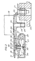
- Figure 2 is a cross-section through the casing.
- The floor cleaning apparatus comprises a
main casing 10 on which are mountedwheel 11 for use in moving the apparatus from one point of use to another or to storage. Hinged to the rear of thecasing 10 by ahinge connection 12 is ahandle 13 provided at its upper end with acontrol box 14 andhand grips 15. Secured to themain casing 10 is a cowling 16 to which is detachably fixed acircular skirt 17 which in use of the apparatus extends to the floor and surrounds the periphery of a rotatable circular brush, pad or mop (not shown). The bottom edge of theskirt 17 is provided with a slot orslots 18 to allow air to flow into the area surrounded by theskirt 17. - Mounted on the upper side of the
main casing 10 is anelectric motor 19 having anoutput shaft 20 which extends through themain casing 10 as shown in Figure 2. Rotatably mounted within themain casing 10 bybearings 21 is a drive disc orplate 22 which the circular brush, pad or mop is detachably secured. Secured to theshaft 20 is apulley 23 which is drivingly connected by abelt 24 to atubular part 25 of the disc orplate 22. - Mounted within the
main casing 10 throughsupport legs 26 is animpeller unit 27 located adjacent to the drive disc orplate 22. Theimpeller unit 27 comprises amounting plate 28 to which is secured ascroll casing 29 having anair inlet 30 and anair outlet 31. Mounted for rotation inbearings 32 is animpeller shaft 33 on which is secured animpeller 34. The upper end of theshaft 33 is provided with apulley 35 which is drivingly engaged with asecond pulley 36 provided on theshaft 20 by means of abelt 37. - The
outlet 31 is connected via aconduit 38 to a filteredreceptacle 39 carried by thehandle 13. - In use of the apparatus, the
skirt 17 prevents dust and/or debris being thrown into the surrounding area and atmosphere by the brush, pad or mop and as the area contained within theskirt 17 andcasing 10 is subjected to suction by theimpeller unit 27 any dust and/or debris is conveyed to the filteredreceptacle 39. If the apparatus is used on a wet floor any water sucked up by theimpeller unit 27 is conveyed to thereceptacle 39 and can not come into contact with themotor 19. As only asingle motor 19 is used to drive thedisc 22 and theimpeller unit 27 the operation of the machine is quiet compared with apparatus having two motors. - By having the
impeller unit 27 mounted on thecasing 10 instead of on thehandle 13 ensures that its weight is distributed low down on the apparatus and does not adversely effect handling of the apparatus. - It will be appreciated that the drive transmissions to the
disc 22 andimpeller unit 27 may comprise a gear transmission or a chain and sprocket transmission, or other alternative transmission. - One or both drive transmissions to the
disc 22 and theimpeller unit 27 may include a jockey or tensioning pulley or sprocket.
Claims (6)
1. A floor cleaning apparatus having a main casing (10), a disc or plate (22) mounted for rotation within the casing (10) and to which a circular brush, pad or mop can be attached, a skirt (17) surrounding the periphery of the disc or plate (22), a fan or impeller unit (27) for providing suction within the area bounded by the skirt (17) and electrically driven means for driving the disc or plate (22) and the impeller unit (27), characterised in that the fan or impeller unit (27) is located within the casing (10) and has a conduit (38) which extends to a filtered receptacle (39) and the electrically driven means for driving the disc or plate (22) and the impeller unit (27) comprises an electric motor (19) mounted on the casing (10) with its drive shaft (20) extending within the casing (10), a first drive transmission (23, 24) drivingly connecting the drive shaft (20) to the disc or plate (22) and a second drive transmission (35, 36, 37) drivingly connecting the drive shaft (20) to the fan or impeller unit (27).
2. A floor cleaning apparatus as claimed in claim 1, in which the first drive transmission (23, 24) and the second drive transmission (35, 36, 37) each comprise a belt and pulley drive transmission or a chain and sprocket drive transmission.
3. A floor cleaning apparatus as claimed in claim 2, in which one or both drive transmission (23, 24) and (35, 36, 37) include a jockey or tensioning pulley or sprocket.
4. A floor cleaning apparatus as claimed in any preceding claim, in which the main casing (10) is provided with wheels (11).
5. A floor cleaning apparatus as claimed in any preceding claim, in which the main casing (10) is provided with a cowling (16) to which the skirt (17) is detachably fixed.
6. A floor cleaning apparatus as claimed in any preceding claim, in which the skirt (17) is provided at its bottom edge with a slot or slots (18).
Applications Claiming Priority (2)
| Application Number | Priority Date | Filing Date | Title |
|---|---|---|---|
| GB8712446 | 1987-05-27 | ||
| GB878712446A GB8712446D0 (en) | 1987-05-27 | 1987-05-27 | Floor cleaning apparatus |
Publications (2)
| Publication Number | Publication Date |
|---|---|
| EP0293149A2 true EP0293149A2 (en) | 1988-11-30 |
| EP0293149A3 EP0293149A3 (en) | 1989-06-28 |
Family
ID=10617972
Family Applications (1)
| Application Number | Title | Priority Date | Filing Date |
|---|---|---|---|
| EP88304639A Withdrawn EP0293149A3 (en) | 1987-05-27 | 1988-05-23 | Floor cleaning apparatus |
Country Status (2)
| Country | Link |
|---|---|
| EP (1) | EP0293149A3 (en) |
| GB (1) | GB8712446D0 (en) |
Cited By (6)
| Publication number | Priority date | Publication date | Assignee | Title |
|---|---|---|---|---|
| GB2260892A (en) * | 1991-11-01 | 1993-05-05 | Gold Star Co | A vacuum cleaner head with detachable mop |
| WO2004073476A1 (en) * | 2003-02-21 | 2004-09-02 | Joseph Deleo | Polishing vacuum cleaner for hard surfaces |
| EP1762166A3 (en) * | 2005-09-09 | 2008-01-02 | Samsung Gwangju Electronics Co., Ltd. | Vacuum cleaner having a suction motor and means to decelerate rotation of the fan drive shaft |
| WO2010009941A1 (en) * | 2008-07-23 | 2010-01-28 | Alfred Kärcher Gmbh & Co. Kg | Floor cleaning device |
| CN111990933A (en) * | 2020-09-17 | 2020-11-27 | 于秀超 | Intelligent household labor-saving mop |
| GB2622024A (en) * | 2022-08-31 | 2024-03-06 | Dyson Technology Ltd | Drive system for a floor cleaner |
Family Cites Families (5)
| Publication number | Priority date | Publication date | Assignee | Title |
|---|---|---|---|---|
| US2898622A (en) * | 1955-11-30 | 1959-08-11 | Hoover Co | Combination suction cleaners |
| GB871241A (en) * | 1956-11-30 | 1961-06-21 | Cimex Ltd | An improved floor polishing machine |
| GB935263A (en) * | 1961-10-19 | 1963-08-28 | R G Dixon And Company Ltd | Improvements in or relating to floor polishing or cleaning machines |
| AU414936B2 (en) * | 1967-02-03 | 1971-07-14 | Contract Cleaning Co. Pty. Limited | Combined floor-polisher and suction cleaner |
| DE1628817C3 (en) * | 1967-05-10 | 1975-07-03 | G. Staehle Kg, 7000 Stuttgart | Floor cleaning machine with a single disc brush |
-
1987
- 1987-05-27 GB GB878712446A patent/GB8712446D0/en active Pending
-
1988
- 1988-05-23 EP EP88304639A patent/EP0293149A3/en not_active Withdrawn
Cited By (8)
| Publication number | Priority date | Publication date | Assignee | Title |
|---|---|---|---|---|
| GB2260892A (en) * | 1991-11-01 | 1993-05-05 | Gold Star Co | A vacuum cleaner head with detachable mop |
| GB2260892B (en) * | 1991-11-01 | 1995-05-31 | Gold Star Co | Cleaner head for a vacuum cleaner |
| WO2004073476A1 (en) * | 2003-02-21 | 2004-09-02 | Joseph Deleo | Polishing vacuum cleaner for hard surfaces |
| EP1762166A3 (en) * | 2005-09-09 | 2008-01-02 | Samsung Gwangju Electronics Co., Ltd. | Vacuum cleaner having a suction motor and means to decelerate rotation of the fan drive shaft |
| WO2010009941A1 (en) * | 2008-07-23 | 2010-01-28 | Alfred Kärcher Gmbh & Co. Kg | Floor cleaning device |
| CN111990933A (en) * | 2020-09-17 | 2020-11-27 | 于秀超 | Intelligent household labor-saving mop |
| CN111990933B (en) * | 2020-09-17 | 2021-08-06 | 金华市海丰实业有限公司 | Intelligent household labor-saving mop |
| GB2622024A (en) * | 2022-08-31 | 2024-03-06 | Dyson Technology Ltd | Drive system for a floor cleaner |
Also Published As
| Publication number | Publication date |
|---|---|
| GB8712446D0 (en) | 1987-07-01 |
| EP0293149A3 (en) | 1989-06-28 |
Similar Documents
| Publication | Publication Date | Title |
|---|---|---|
| US5287581A (en) | Cleaning device having at least one rotating cylindrical sponge | |
| US5018240A (en) | Carpet cleaner | |
| RU2121288C1 (en) | Vacuum cleaner | |
| EP1769711A2 (en) | Floorcloth attached suction brush for vacuum cleaner | |
| AU564909B2 (en) | High speed floor buffing machine and floor buffing method | |
| US6892420B1 (en) | Vacuum cleaner with hair wrap cutter | |
| US4178654A (en) | Floor polishing machines | |
| US7669622B2 (en) | Jointer/planer with internal sawdust collection system | |
| CN1507829A (en) | Rotary brush device and vacuum cleaner using the device | |
| EP1048258A2 (en) | Electric blower and vacuum cleaner using the same | |
| US4996737A (en) | Vacuum cleaner power nozzle | |
| KR19980023805A (en) | Brush Drive for Vacuum Cleaner | |
| KR20090084227A (en) | Bypass type cleaning device | |
| EP0227644A2 (en) | Portable electrical machine tool for the machining of surfaces of materials with dust discharge duct included in the gripping handle | |
| EP0293149A2 (en) | Floor cleaning apparatus | |
| WO2018084784A1 (en) | A dust removal arrangement for an engine-driven tool | |
| US6595838B1 (en) | Wood floor sanding machine | |
| JP2639155B2 (en) | Electric vacuum cleaner | |
| EP1833344A1 (en) | Vacuum cleaner | |
| RU2019606C1 (en) | Cutting belt machine | |
| RU2002127559A (en) | UNIVERSAL FLAT GRINDING MACHINE | |
| JP3128046B2 (en) | Vacuum cleaner suction body | |
| WO1992011794A1 (en) | Cleaner | |
| WO2004073476A1 (en) | Polishing vacuum cleaner for hard surfaces | |
| JPS6150542A (en) | vacuum cleaner |
Legal Events
| Date | Code | Title | Description |
|---|---|---|---|
| PUAI | Public reference made under article 153(3) epc to a published international application that has entered the european phase |
Free format text: ORIGINAL CODE: 0009012 |
|
| AK | Designated contracting states |
Kind code of ref document: A2 Designated state(s): CH DE FR GB IT LI NL |
|
| PUAL | Search report despatched |
Free format text: ORIGINAL CODE: 0009013 |
|
| AK | Designated contracting states |
Kind code of ref document: A3 Designated state(s): CH DE FR GB IT LI NL |
|
| STAA | Information on the status of an ep patent application or granted ep patent |
Free format text: STATUS: THE APPLICATION IS DEEMED TO BE WITHDRAWN |
|
| 18D | Application deemed to be withdrawn |
Effective date: 19891229 |