EP0227644A2 - Portable electrical machine tool for the machining of surfaces of materials with dust discharge duct included in the gripping handle - Google Patents
Portable electrical machine tool for the machining of surfaces of materials with dust discharge duct included in the gripping handle Download PDFInfo
- Publication number
- EP0227644A2 EP0227644A2 EP87200132A EP87200132A EP0227644A2 EP 0227644 A2 EP0227644 A2 EP 0227644A2 EP 87200132 A EP87200132 A EP 87200132A EP 87200132 A EP87200132 A EP 87200132A EP 0227644 A2 EP0227644 A2 EP 0227644A2
- Authority
- EP
- European Patent Office
- Prior art keywords
- gripping handle
- discharge duct
- machine tool
- fan means
- machining
- Prior art date
- Legal status (The legal status is an assumption and is not a legal conclusion. Google has not performed a legal analysis and makes no representation as to the accuracy of the status listed.)
- Withdrawn
Links
Images
Classifications
-
- B—PERFORMING OPERATIONS; TRANSPORTING
- B23—MACHINE TOOLS; METAL-WORKING NOT OTHERWISE PROVIDED FOR
- B23Q—DETAILS, COMPONENTS, OR ACCESSORIES FOR MACHINE TOOLS, e.g. ARRANGEMENTS FOR COPYING OR CONTROLLING; MACHINE TOOLS IN GENERAL CHARACTERISED BY THE CONSTRUCTION OF PARTICULAR DETAILS OR COMPONENTS; COMBINATIONS OR ASSOCIATIONS OF METAL-WORKING MACHINES, NOT DIRECTED TO A PARTICULAR RESULT
- B23Q11/00—Accessories fitted to machine tools for keeping tools or parts of the machine in good working condition or for cooling work; Safety devices specially combined with or arranged in, or specially adapted for use in connection with, machine tools
- B23Q11/0042—Devices for removing chips
- B23Q11/0046—Devices for removing chips by sucking
-
- B—PERFORMING OPERATIONS; TRANSPORTING
- B24—GRINDING; POLISHING
- B24B—MACHINES, DEVICES, OR PROCESSES FOR GRINDING OR POLISHING; DRESSING OR CONDITIONING OF ABRADING SURFACES; FEEDING OF GRINDING, POLISHING, OR LAPPING AGENTS
- B24B55/00—Safety devices for grinding or polishing machines; Accessories fitted to grinding or polishing machines for keeping tools or parts of the machine in good working condition
- B24B55/06—Dust extraction equipment on grinding or polishing machines
- B24B55/10—Dust extraction equipment on grinding or polishing machines specially designed for portable grinding machines, e.g. hand-guided
- B24B55/105—Dust extraction equipment on grinding or polishing machines specially designed for portable grinding machines, e.g. hand-guided with oscillating tools
Definitions
- the present invention relates to an electrical portable polishing machine tool for the machining of surfaces of materials with simplified suction of the dust produced during the abrasion operative step.
- Tool machines of this type which essentially comprise a main body, enclosing a vertical-axis electrical motor, provided with a handle and assembled, by means of the interposition of elastic elements, on a polishing plate on which an abrasive sheet is positioned.
- Said plate and said abrasive sheet are provided with a plurality of apertures for the passage and the suction of the dust created by the polishing action by the same abrasive sheet.
- the produced dust is sucked inside the body of the machine tool and is discharged through a discharge duct extending outside the tool handle, substantially parallel to the same.
- Object of the present invention is to provide a polishing tool machine in which the dust sucking means do not occupy extra space beyond the space normally occupied by the machine body and the handle.
- an electrical portable machine tool for the machining of surfaces of materials comprises a main body provided with a gripping handle, a polishing plate onto which an abrasive sheet is placed, said plate and said sheet being provided with aligned apertures for dust passage, fan means for sucking the dust produced by the surface machining through said aligned apertures, a discharge duct for discharging the dust sucked by said fan means and motor means for driving said polishing plate and said fan means, characterized in that said gripping handle has a cross-section shaped as a reverse U and said discharge duct consists of a tubular element arranged at a lower portion of said gripping handle as a closure for the same.
- the discharge duct is no longer a separate piece, but is included in the gripping handle as a closure member of the same.
- a cavity is defined inside the handle, along which the power feeding cable may extend.
- an electrical portable polishing machine comprises essentially a body formed by an upper cap 10, by a central portion 11 and by a lower portion 12, rigidly linked to each other so as to constitute a single body supporting a vertical-axis electrical motor 13.
- an eccentric element 15 is keyed, on whichis rotatably mounted a support 16 for a covering portion 17 of a polishing plate 18 under which an abrasive sheet 19 is positioned and fastened in a known fashion.
- a lateral chamber 22 is provided, from which a duct 23 extends, which is operatively connected with a discharge tubular element 24, ending into a connector or fitting 25, said tubular element 24 constituting the lower portion of the gripping handle 20.
- Said gripping handle 20 indeed, essentially having a reversed-U shape (Fig. 4), is closed by said tubular element 24, and houses additionally a cable 26 for the feeding of the motor 13, as well as possible electric devices for the machine operation.
- the chamber 22 contains a fan 27 which receives its rotary motion from a shaft 28 solid with a first gear wheel 29, operatively coupled to and driven for rotation by a second gear wheel 30 keyed onto the shaft 14 of the motor 13.
- Said chamber 22 is provided in its lower portion with an aperture 31 connected, via an elastic bellows-shaped element 32, with a port 33 provided in the upper portion of the cover 17 of the polishing plate 18.
- the polishing plate 18 is provided with a plurality of apertures 35 aligned with corresponding apertures 36 provided in the abrasive sheet 19.
- Said plurality of apertures are connected to a chamber 37 defined between said cover and said plate, and connected with the port 33.
- the dust formed is sucked, according to the arrows of Fig. 2, from the apertures 36, 35, passes into the chamber 37 and through the port 33, the bellows 32 and the aperture 31 and comes into the chamber 22 wherein the fan 27 is housed.
- the dust is then sent through the duct 23 and the tubular element 24 to a collecting means, which may be either positioned solid with the connector 25 or placed in a remote site and connected with it viaa flexible pipe, not shown.
- the greater or lesser adhesion between the abrasive sheet and the material under machining by influencing the motor speed, causes consequently an equal adjustment of the turning speed of the fan 27, thus varying the suction efficiency.
- tubular element 24 besides acting as suction duct, performs the function of lower closure of the gripping handle 20 and is hence suitable to be easily fitted to it.
Abstract
Description
- The present invention relates to an electrical portable polishing machine tool for the machining of surfaces of materials with simplified suction of the dust produced during the abrasion operative step.
- Tool machines of this type are known, which essentially comprise a main body, enclosing a vertical-axis electrical motor, provided with a handle and assembled, by means of the interposition of elastic elements, on a polishing plate on which an abrasive sheet is positioned.
- Said plate and said abrasive sheet are provided with a plurality of apertures for the passage and the suction of the dust created by the polishing action by the same abrasive sheet. The produced dust is sucked inside the body of the machine tool and is discharged through a discharge duct extending outside the tool handle, substantially parallel to the same.
- The presence of a separate discharge duct, to which a small bag for collecting the sucked dust is generally applied, is often an impediment for the handling of such tools, in addition to the presence of a power feeding cable extending from the same handle.
- Object of the present invention is to provide a polishing tool machine in which the dust sucking means do not occupy extra space beyond the space normally occupied by the machine body and the handle.
- In view of this object, according to the present invention, an electrical portable machine tool for the machining of surfaces of materials comprises a main body provided with a gripping handle, a polishing plate onto which an abrasive sheet is placed, said plate and said sheet being provided with aligned apertures for dust passage, fan means for sucking the dust produced by the surface machining through said aligned apertures, a discharge duct for discharging the dust sucked by said fan means and motor means for driving said polishing plate and said fan means, characterized in that said gripping handle has a cross-section shaped as a reverse U and said discharge duct consists of a tubular element arranged at a lower portion of said gripping handle as a closure for the same.
- In this way, the discharge duct is no longer a separate piece, but is included in the gripping handle as a closure member of the same. A cavity is defined inside the handle, along which the power feeding cable may extend.
- The structural and functional characteristics of a machine according to the present invention shall be better understood from the following exemplifying and not limitative disclosure, referred to the attached schematic drawings, wherein:
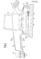
- Figure 1 is a side elevation view of a machine according to the invention;
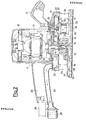
- Fig. 2 is an elevation view equivalent to that of Fig. 1, partly in section;
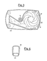
- Fig. 3 is a sectional view according to line III-III of Fig. 1, and
- Fig. 4 is a sectional view according to line IV-IV of Fig. 1.
- As shown in Fig. 1 and 2, an electrical portable polishing machine comprises essentially a body formed by an
upper cap 10, by acentral portion 11 and by alower portion 12, rigidly linked to each other so as to constitute a single body supporting a vertical-axiselectrical motor 13. - On the
shaft 14 of saidmotor 13 aneccentric element 15 is keyed, on whichis rotatably mounted asupport 16 for a coveringportion 17 of apolishing plate 18 under which anabrasive sheet 19 is positioned and fastened in a known fashion. - From the
central portion 11 protrude: on one side agripping handle 20 and on the other side a gripping and pressure-exertingelement 21. - In the lower portion a lateral chamber 22 is provided, from which a
duct 23 extends, which is operatively connected with a dischargetubular element 24, ending into a connector or fitting 25, saidtubular element 24 constituting the lower portion of thegripping handle 20. - Said
gripping handle 20 indeed, essentially having a reversed-U shape (Fig. 4), is closed by saidtubular element 24, and houses additionally acable 26 for the feeding of themotor 13, as well as possible electric devices for the machine operation. - The chamber 22 contains a
fan 27 which receives its rotary motion from ashaft 28 solid with afirst gear wheel 29, operatively coupled to and driven for rotation by asecond gear wheel 30 keyed onto theshaft 14 of themotor 13. - Said chamber 22 is provided in its lower portion with an
aperture 31 connected, via an elastic bellows-shaped element 32, with aport 33 provided in the upper portion of thecover 17 of thepolishing plate 18. - Between said
lower portion 12 and saidcover 17 there are a plurality of column-shapedelastic elements 34, suitable to allow the orbital motion of the same plate and to prevent it from rotating. - The
polishing plate 18 is provided with a plurality ofapertures 35 aligned withcorresponding apertures 36 provided in theabrasive sheet 19. - Said plurality of apertures are connected to a
chamber 37 defined between said cover and said plate, and connected with theport 33. - When the electrical polishing machine comes in contact with the surface of the material to be polished, the orbital movement of the
polishing plate 18 and of the relatedabrasive sheet 19 positioned onto it cause the formation of dust. - The dust formed is sucked, according to the arrows of Fig. 2, from the
apertures chamber 37 and through theport 33, thebellows 32 and theaperture 31 and comes into the chamber 22 wherein thefan 27 is housed. - From said chamber the dust is then sent through the
duct 23 and thetubular element 24 to a collecting means, which may be either positioned solid with theconnector 25 or placed in a remote site and connected with it viaa flexible pipe, not shown. - It results particularly advantageous the provision of the two
gear wheels fan 27 to turn at a higher speed than themotor 13, thus allowing a considerable suction. - Advantageously, the greater or lesser adhesion between the abrasive sheet and the material under machining, by influencing the motor speed, causes consequently an equal adjustment of the turning speed of the
fan 27, thus varying the suction efficiency. - It is also advantageous to note that the
tubular element 24, besides acting as suction duct, performs the function of lower closure of thegripping handle 20 and is hence suitable to be easily fitted to it.
Claims (4)
Applications Claiming Priority (2)
| Application Number | Priority Date | Filing Date | Title |
|---|---|---|---|
| IT2053785U | 1985-01-18 | ||
| IT8520537U IT8520537V0 (en) | 1985-01-18 | 1985-01-18 | PORTABLE ELECTRIC MACHINE TOOL MACHINE FOR THE PROCESSING OF SURFACES OF MATERIALS WITH AMPLIFIED ASPIRATION OF THE DUST PRODUCED. |
Related Parent Applications (2)
| Application Number | Title | Priority Date | Filing Date |
|---|---|---|---|
| EP86200028.8 Division | 1986-01-09 | ||
| EP86200028A Division EP0190775B1 (en) | 1985-01-18 | 1986-01-09 | Portable electrical polishing machine tool for the machining of surfaces of materials with simplified suction of the dust produced |
Publications (2)
| Publication Number | Publication Date |
|---|---|
| EP0227644A2 true EP0227644A2 (en) | 1987-07-01 |
| EP0227644A3 EP0227644A3 (en) | 1989-08-16 |
Family
ID=11168435
Family Applications (2)
| Application Number | Title | Priority Date | Filing Date |
|---|---|---|---|
| EP86200028A Expired EP0190775B1 (en) | 1985-01-18 | 1986-01-09 | Portable electrical polishing machine tool for the machining of surfaces of materials with simplified suction of the dust produced |
| EP87200132A Withdrawn EP0227644A3 (en) | 1985-01-18 | 1986-01-09 | Portable electrical machine tool for the machining of surfaces of materials with dust discharge duct included in the gripping handle |
Family Applications Before (1)
| Application Number | Title | Priority Date | Filing Date |
|---|---|---|---|
| EP86200028A Expired EP0190775B1 (en) | 1985-01-18 | 1986-01-09 | Portable electrical polishing machine tool for the machining of surfaces of materials with simplified suction of the dust produced |
Country Status (3)
| Country | Link |
|---|---|
| EP (2) | EP0190775B1 (en) |
| DE (1) | DE3665142D1 (en) |
| IT (1) | IT8520537V0 (en) |
Cited By (10)
| Publication number | Priority date | Publication date | Assignee | Title |
|---|---|---|---|---|
| EP0301269A2 (en) * | 1987-07-25 | 1989-02-01 | C. & E. FEIN GmbH & Co. | Grinding machine with dust sucking means |
| EP0558893A2 (en) * | 1992-02-05 | 1993-09-08 | Festo KG | Motor driven appliance being designed as handhold appliance for grinding, polishing, derosting or suchlike treatment of surfaces |
| GB2293123A (en) * | 1994-09-16 | 1996-03-20 | Bosch Gmbh Robert | Hand-guided continuous belt grinding machine has perforations in the belt and apertures in the base plate through which dust extraction is effected |
| US5595530A (en) * | 1995-01-31 | 1997-01-21 | Dynabrade, Inc. | Reciprocating sander |
| US5597347A (en) * | 1995-02-09 | 1997-01-28 | Porter-Cable Corporation | Sander vacuum housing and pad frame system |
| US5743791A (en) * | 1995-02-09 | 1998-04-28 | Porter Cable Corporation | Sanding system |
| US5759094A (en) * | 1995-02-09 | 1998-06-02 | Porter-Cable Corporation | In-line detail sander |
| US6179696B1 (en) | 1998-04-29 | 2001-01-30 | Black & Decker Inc. | Powered oscillating hand tool |
| CN113896004A (en) * | 2021-10-14 | 2022-01-07 | 浙江佳维康特种纸有限公司 | Papermaking production line with dust collecting system |
| GB2620109A (en) * | 2022-06-13 | 2024-01-03 | Cole Oliver | Dust extraction hose |
Families Citing this family (6)
| Publication number | Priority date | Publication date | Assignee | Title |
|---|---|---|---|---|
| EP0407836A3 (en) * | 1989-07-04 | 1991-04-24 | Mitsubishi Metal Corporation | Rotary cutting tool |
| DE29707040U1 (en) * | 1997-04-18 | 1998-08-13 | Buchter Gerd | Machine grinder, grater or polisher |
| CH695141A5 (en) * | 2001-03-05 | 2005-12-30 | Lux Asia Pacific Pte Ltd The L | Surface processing device is for use with suction apparatus, to hose or tube of which it is fixed |
| GB0208806D0 (en) * | 2002-04-17 | 2002-05-29 | Rieke Corp | Dispenser pumps |
| DE102007014766A1 (en) * | 2007-03-28 | 2008-10-02 | Robert Bosch Gmbh | Eccentric disc grinder |
| DE102011003223A1 (en) * | 2011-01-27 | 2012-08-02 | Robert Bosch Gmbh | Method and device for removing removing particles resulting from floor or wall processing of a surface by means of a motorized grinding tool |
Citations (2)
| Publication number | Priority date | Publication date | Assignee | Title |
|---|---|---|---|---|
| US3938283A (en) * | 1975-02-24 | 1976-02-17 | The Singer Company | Dust bag support |
| FR2522498A1 (en) * | 1982-03-02 | 1983-09-09 | Black & Decker Inc | LOW VOLTAGE PORTABLE APPARATUS WITH SUCTION FOR CUTTING PLASTERS |
Family Cites Families (8)
| Publication number | Priority date | Publication date | Assignee | Title |
|---|---|---|---|---|
| DE620782C (en) * | 1935-10-26 | Ludwig Roemer | Transportable, electrically driven wood sanding machine with sanding pad | |
| US2774199A (en) * | 1951-09-15 | 1956-12-18 | Porter Cable Machine Co | Abrading machine |
| DE1652152A1 (en) * | 1967-02-04 | 1970-05-06 | Relu Gebr Seitz Ohg | Hand surface grinding machine, so-called slipper |
| IT943563B (en) * | 1970-11-04 | 1973-04-10 | Mafell Maschinenfabrik Mey R K | SANDER IN PARTICULAR HONED RE WITH VIBRATING TOOL WITH VENTS AND VACUUM CLEANER |
| GB1364025A (en) * | 1971-10-01 | 1974-08-21 | Stoll Kg Kurt | Hand grinders |
| US3902284A (en) * | 1974-12-17 | 1975-09-02 | Singer Co | Low profile blower assembly for portable belt sanders |
| DE2907930C2 (en) * | 1979-03-01 | 1982-12-16 | Festo-Maschinenfabrik Gottlieb Stoll, 7300 Esslingen | Pneumatic hand grinder |
| JPS607953U (en) * | 1983-06-27 | 1985-01-19 | リョービ株式会社 | sander dust collector |
-
1985
- 1985-01-18 IT IT8520537U patent/IT8520537V0/en unknown
-
1986
- 1986-01-09 EP EP86200028A patent/EP0190775B1/en not_active Expired
- 1986-01-09 EP EP87200132A patent/EP0227644A3/en not_active Withdrawn
- 1986-01-09 DE DE8686200028T patent/DE3665142D1/en not_active Expired
Patent Citations (2)
| Publication number | Priority date | Publication date | Assignee | Title |
|---|---|---|---|---|
| US3938283A (en) * | 1975-02-24 | 1976-02-17 | The Singer Company | Dust bag support |
| FR2522498A1 (en) * | 1982-03-02 | 1983-09-09 | Black & Decker Inc | LOW VOLTAGE PORTABLE APPARATUS WITH SUCTION FOR CUTTING PLASTERS |
Cited By (18)
| Publication number | Priority date | Publication date | Assignee | Title |
|---|---|---|---|---|
| EP0301269A2 (en) * | 1987-07-25 | 1989-02-01 | C. & E. FEIN GmbH & Co. | Grinding machine with dust sucking means |
| EP0301269A3 (en) * | 1987-07-25 | 1990-02-28 | & E. Fein Gmbh & Co. C. | Grinding machine with dust sucking means |
| EP0558893A2 (en) * | 1992-02-05 | 1993-09-08 | Festo KG | Motor driven appliance being designed as handhold appliance for grinding, polishing, derosting or suchlike treatment of surfaces |
| EP0558893B1 (en) * | 1992-02-05 | 1996-05-01 | Festo KG | Motor driven appliance being designed as handhold appliance for grinding, polishing, derosting or suchlike treatment of surfaces |
| GB2293123A (en) * | 1994-09-16 | 1996-03-20 | Bosch Gmbh Robert | Hand-guided continuous belt grinding machine has perforations in the belt and apertures in the base plate through which dust extraction is effected |
| GB2293123B (en) * | 1994-09-16 | 1996-08-28 | Bosch Gmbh Robert | Hand-guided electric belt grinding machine |
| US5595530A (en) * | 1995-01-31 | 1997-01-21 | Dynabrade, Inc. | Reciprocating sander |
| US5743791A (en) * | 1995-02-09 | 1998-04-28 | Porter Cable Corporation | Sanding system |
| US5597347A (en) * | 1995-02-09 | 1997-01-28 | Porter-Cable Corporation | Sander vacuum housing and pad frame system |
| US5759094A (en) * | 1995-02-09 | 1998-06-02 | Porter-Cable Corporation | In-line detail sander |
| US6042460A (en) * | 1995-02-09 | 2000-03-28 | Porter-Cable Corporation | In-line sander |
| US6257969B1 (en) | 1995-02-09 | 2001-07-10 | Porter-Cable/Delta | In-line sander |
| US8167683B2 (en) | 1995-02-09 | 2012-05-01 | Black & Decker Inc. | In-line sander |
| US6179696B1 (en) | 1998-04-29 | 2001-01-30 | Black & Decker Inc. | Powered oscillating hand tool |
| USRE40345E1 (en) * | 1998-04-29 | 2008-05-27 | Black & Decker, Inc. | Powered oscillating hand tool |
| CN113896004A (en) * | 2021-10-14 | 2022-01-07 | 浙江佳维康特种纸有限公司 | Papermaking production line with dust collecting system |
| CN113896004B (en) * | 2021-10-14 | 2024-02-27 | 浙江佳维康特种纸有限公司 | Papermaking production line with dust collecting system |
| GB2620109A (en) * | 2022-06-13 | 2024-01-03 | Cole Oliver | Dust extraction hose |
Also Published As
| Publication number | Publication date |
|---|---|
| IT8520537V0 (en) | 1985-01-18 |
| DE3665142D1 (en) | 1989-10-05 |
| EP0227644A3 (en) | 1989-08-16 |
| EP0190775A1 (en) | 1986-08-13 |
| EP0190775B1 (en) | 1989-08-23 |
Similar Documents
| Publication | Publication Date | Title |
|---|---|---|
| EP0227644A2 (en) | Portable electrical machine tool for the machining of surfaces of materials with dust discharge duct included in the gripping handle | |
| US5626510A (en) | Power tool for surface treatment | |
| RU2590426C2 (en) | Processing machine, primarily electrical machine | |
| US5637034A (en) | Detail sander | |
| US20020129949A1 (en) | Suction module | |
| KR20060048846A (en) | Self-traveling cleaner | |
| KR970032722A (en) | Cordless cleaner | |
| EP2085009A2 (en) | Cleaning apparatus | |
| EP0252552A1 (en) | Manual electrical tool with motor and dust suction means incorporated in the handle | |
| US4928505A (en) | Powered portable wringer | |
| EP0309083B1 (en) | Cleaning tools | |
| US4177535A (en) | Polishing apparatus | |
| JP4004307B2 (en) | Keren machine | |
| EP0293149A2 (en) | Floor cleaning apparatus | |
| EP0272725A2 (en) | Portable electric tool with balanced orbital movement | |
| GB2383007A (en) | Improvements to a hand tool machine. | |
| CN218017718U (en) | Coarse polishing machine | |
| US6996874B2 (en) | Air jet for machine tool to clean cutting dust | |
| JPH0231721A (en) | Charging type cleaner | |
| CN1684797A (en) | Manual grinding machine comprising a dust extraction device | |
| CN220740466U (en) | Even polisher of gravity distribution | |
| CN211029448U (en) | Polishing tool | |
| JPH0530458B2 (en) | ||
| CN220699161U (en) | Polishing tool | |
| JP3214020B2 (en) | Vacuum cleaner suction tool |
Legal Events
| Date | Code | Title | Description |
|---|---|---|---|
| PUAI | Public reference made under article 153(3) epc to a published international application that has entered the european phase |
Free format text: ORIGINAL CODE: 0009012 |
|
| AC | Divisional application: reference to earlier application |
Ref document number: 190775 Country of ref document: EP |
|
| AK | Designated contracting states |
Kind code of ref document: A2 Designated state(s): BE CH DE FR GB IT LI NL |
|
| PUAL | Search report despatched |
Free format text: ORIGINAL CODE: 0009013 |
|
| AK | Designated contracting states |
Kind code of ref document: A3 Designated state(s): BE CH DE FR GB IT LI NL |
|
| 17P | Request for examination filed |
Effective date: 19891229 |
|
| 17Q | First examination report despatched |
Effective date: 19910322 |
|
| STAA | Information on the status of an ep patent application or granted ep patent |
Free format text: STATUS: THE APPLICATION IS DEEMED TO BE WITHDRAWN |
|
| 18D | Application deemed to be withdrawn |
Effective date: 19910802 |