EP0292185B1 - Cam mechanisms - Google Patents
Cam mechanisms Download PDFInfo
- Publication number
- EP0292185B1 EP0292185B1 EP88304256A EP88304256A EP0292185B1 EP 0292185 B1 EP0292185 B1 EP 0292185B1 EP 88304256 A EP88304256 A EP 88304256A EP 88304256 A EP88304256 A EP 88304256A EP 0292185 B1 EP0292185 B1 EP 0292185B1
- Authority
- EP
- European Patent Office
- Prior art keywords
- cam
- cam follower
- follower
- face
- disc
- Prior art date
- Legal status (The legal status is an assumption and is not a legal conclusion. Google has not performed a legal analysis and makes no representation as to the accuracy of the status listed.)
- Expired - Lifetime
Links
- 230000007246 mechanism Effects 0.000 title claims abstract description 28
- 230000015572 biosynthetic process Effects 0.000 claims abstract description 23
- 239000012530 fluid Substances 0.000 description 4
- 238000013016 damping Methods 0.000 description 3
- 238000002485 combustion reaction Methods 0.000 description 2
- 230000004048 modification Effects 0.000 description 2
- 238000012986 modification Methods 0.000 description 2
- 230000009471 action Effects 0.000 description 1
- 230000001010 compromised effect Effects 0.000 description 1
- 230000000694 effects Effects 0.000 description 1
- 239000000446 fuel Substances 0.000 description 1
- 230000009467 reduction Effects 0.000 description 1
- 230000004044 response Effects 0.000 description 1
Images


Classifications
-
- F—MECHANICAL ENGINEERING; LIGHTING; HEATING; WEAPONS; BLASTING
- F01—MACHINES OR ENGINES IN GENERAL; ENGINE PLANTS IN GENERAL; STEAM ENGINES
- F01L—CYCLICALLY OPERATING VALVES FOR MACHINES OR ENGINES
- F01L13/00—Modifications of valve-gear to facilitate reversing, braking, starting, changing compression ratio, or other specific operations
- F01L13/0015—Modifications of valve-gear to facilitate reversing, braking, starting, changing compression ratio, or other specific operations for optimising engine performances by modifying valve lift according to various working parameters, e.g. rotational speed, load, torque
- F01L13/0031—Modifications of valve-gear to facilitate reversing, braking, starting, changing compression ratio, or other specific operations for optimising engine performances by modifying valve lift according to various working parameters, e.g. rotational speed, load, torque by modification of tappet or pushrod length
-
- F—MECHANICAL ENGINEERING; LIGHTING; HEATING; WEAPONS; BLASTING
- F01—MACHINES OR ENGINES IN GENERAL; ENGINE PLANTS IN GENERAL; STEAM ENGINES
- F01L—CYCLICALLY OPERATING VALVES FOR MACHINES OR ENGINES
- F01L1/00—Valve-gear or valve arrangements, e.g. lift-valve gear
- F01L1/12—Transmitting gear between valve drive and valve
- F01L1/14—Tappets; Push rods
- F01L1/143—Tappets; Push rods for use with overhead camshafts
Definitions
- the present invention relates to cam mechanisms and in particular, although not exclusively, to cam mechanisms used to control the inlet and exhaust valves of internal combustion engines.
- the present invention provides a cam mechanism of the type disclosed in FR-A-543706.
- FR-A-1245669 and GB-A-955988 disclose cam mechanisms which may be adjusted in accordance with the engine speed, to vary the duration of opening of the valves.
- a cam mechanism comprises; a cam of basic circular formation and having a lobe formation extending radially outwardly along part of its periphery; and a cam follower mounted for reciprocating movement along an axis perpendicular to the axis of rotation of the cam; the cam acting against an end face of the cam follower so that engagement of the lobe formation therewith will cause movement of the cam follower, the end face of the cam follower being profiled, characterised in that means are provided for rotating the cam follower axially to vary the angular orientation of the profiled face with respect to the axis of rotation of the cam to adjust the angular positions at which the lobe formation engages and disengages the end face and thus the duration of movement of the cam follower.
- the cam mechanism illustrated in Figures 1 to 4 includes a cam 10 having a lobe formation 11 which projects from a basic circular formation 12.
- the cam 10 is mounted on or formed as a part of a camshaft 13, for rotation therewith.
- the surface 14 of the cam 10 engages the end face 15 of a bucket follower 16.
- the bucket follower 16 is slidingly located perpendicular to the axis of rotation of the cam 10, in a cylindrical bucket guide (not shown) and in the conventional manner would engage the end of the stem of a poppet valve, so that upon rotation of the cam 10, the lobe formation 11 will open and close the poppet valve.
- the end face 15 of the bucket follower 16 is profiled, having a pair of flat surfaces 17 and 18 which are inclined to the axis of the bucket guide, these surfaces being smoothly interconnected by a diametrical arcuate surface 19, of radius equal to the radius of the cam base circle 12.
- the surface 14 of the cam 10 is radiussed across its width, to a radius equal or smaller than the radius of the cam base circle 12.
- the cam 10 can thus engage the profiled face 15 of bucket follower 16, at any orientation of the bucket follower 16.
- Means (not shown) is provided for rotation of the bucket follower 16 in its guide, so that orientation of the profiled face 15 thereof, may be varied with respect to the cam 10.
- This means may be in the form of a rack and pinion mechanism, a rack 21 being mounted transversely of the bucket follower 16 and engaging teeth 22 formed thereon, so that axial movement of the rack 21 will cause rotation of the bucket follower 16. Axial movement of the rack 21 will preferably be controlled by appropriate means in response to the engine speed.
- Duration of movement of the bucket follower 16 between ⁇ and ⁇ + ⁇ may be achieved by rotating the bucket follower 16, so that the face 15 is orientated at angles intermediate of those illustrated in Figures 3 and 4. Furthermore, the angle of inclination of the surfaces 17 and 18 will determine the position of points D and E and consequently by having different angles of inclination, the opening and closing points of the valve may be moved, thus altering the phase relationship between rotation of the cam 10 and opening and closing of the valve.
- a disc 30 is pivotally mounted on the end face 31 of a bucket follower 32 on a diametrical pivot 33, the virtual centre of the pivot 33 being at or near the upper surface 30′ of the disc 30, where it is engaged by a cam 34.
- the end face 31 of bucket follower 32 has a pair of flats 35, 36 which are inclined from the pivot 33 away from disc 30, so as to permit the disc 30 to seesaw about pivot 33.
- FIGs 6A to 6F when the pivot 33 is aligned so that it is parallel to the axis of rotation of the cam 34, rotation of the cam 34 will cause movement of the bucket follower 32 through the following stages:
- the duration of movement of the bucket follower 32 will consequently correspond to rotation of the cam 34 through angle ⁇ - ⁇ , where ⁇ is the angle subtended by the lobe formation 11 and ⁇ is the difference in angles of inclination of faces 35 and 36.
- the cam surface 14 is radiussed across its width to permit tilting of the disc 30
- durations corresponding to angles intermediate of ⁇ and ⁇ - ⁇ may be achieved by rotating the bucket follower 32, so that the pivot 33 is orientated at intermediate angles.
- the above mechanism may be operated at only the two extreme positions discussed above, the orientation of the pivot being switched at a selected engine speed. If used in this manner, the cam surface 14 need not be radiussed across its width.
- angles of inclination of faces 35 and 36 may be varied to vary the opening and closing positions of a valve controlled by bucket follower 32. Where the bucket followers are rotated, this may also be achieved in a manner similar to that described with reference to Figures 1 to 4.
- damping elements control movement of the pivotted disc 30.
- the force required to move the bucket follower 32 is proportional to the square of the speed plus an initial pre-set value for seating an associated valve, while the damper elements would produce a force proportional to the speed.
- the damper elements can thus be arranged at some pre-determined speed, to provide a force greater than that required to move the bucket follower 32, so that at speeds below the pre-determined speed, the bucket follower 32 will not begin to move until the disc 30 engages the inclined face 35, while above the pre-determined speed, the bucket follower 32 will begin to move when disc 30 is at some position intermediate of its horizontal position and the position in which it seats against the inclined face 35, thus increasing the duration of movement of the bucket follower 32, without the need to rotate the bucket follower 32.
- the damping elements are provided by a pair of pistons 40 which are pivotally attached one on either side of the disc 30, these pistons engaging in cylinders 41,42 in the end of bucket follower 32, the cylinders 41,42 being interconnected with a restrictor 43, so that as the disc 30 pivots hydraulic fluid in one cylinder will be forced through restrictor 43 into the other cylinder to provide a damping action.
- annular rubber seal 45 is provided between the disc 30 and the end face 15 of bucket follower 32 to provide a pair of fluid chambers 46 and 47 between the disc 30 and end face 15, these chambers 46 and 47 being separated by the diametrical pivot 33 and being interconnected by a restricted orifice 48 passing through the pivot 33, so that upon pivotal movement of the disc 30 hydraulic fluid will be forced from one chamber to the other.
- a similar effect may be achieved by positioning a ring of suitable elastomeric composition between the disc 30 and the end face of the bucket follower 32.
- these may be connected to a source of hydraulic fluid, the pressure of which may be controlled in relationship to the speed of the engine, so that movement of the disc 30 and hence the duration of movement of the bucket follower 32 may be controlled to provide a continuous variation without the need to rotate the bucket follower 32.
- shims are provided between the bucket follower 32 and the end of the valve stem in order to adjust the valve clearance.
- the thickness of the disc 30 could be varied to provide the required clearance.
- cam mechanisms include rotatable followers
- rotation of all the followers may be controlled by a common device, for example rack mechanism.
Landscapes
- Engineering & Computer Science (AREA)
- Mechanical Engineering (AREA)
- General Engineering & Computer Science (AREA)
- Valve-Gear Or Valve Arrangements (AREA)
- Valve Device For Special Equipments (AREA)
- Polyesters Or Polycarbonates (AREA)
- Gears, Cams (AREA)
- Transmission Devices (AREA)
Abstract
Description
- The present invention relates to cam mechanisms and in particular, although not exclusively, to cam mechanisms used to control the inlet and exhaust valves of internal combustion engines.
- Modern high performance internal combustion engines have been developed to give a maximum power output at high engine speeds. In order to achieve this, the profile of the cam controlling opening and closing of the valves is designed to give high lift with long duration, in order to encourage gas flow at high speeds.
- With such designs, the gas flow at low engine speeds is very much compromised. Under such conditions, incoming air is spilled back into the manifold, due to late closing of the inlet valve, producing a corresponding reduction in the torque output available at low speeds. Also, the exhaust gas is released too early, reducing the expansion ratio of the engine and hence its efficiency. Furthermore, the overlap period where both inlet and exhaust valves are open, is too large and allows free flow of air and fuel through the exhaust valve, thus causing emission problems.
- The present invention provides a cam mechanism of the type disclosed in FR-A-543706. FR-A-1245669 and GB-A-955988 disclose cam mechanisms which may be adjusted in accordance with the engine speed, to vary the duration of opening of the valves.
- According to one aspect of the present invention, a cam mechanism comprises; a cam of basic circular formation and having a lobe formation extending radially outwardly along part of its periphery; and a cam follower mounted for reciprocating movement along an axis perpendicular to the axis of rotation of the cam; the cam acting against an end face of the cam follower so that engagement of the lobe formation therewith will cause movement of the cam follower, the end face of the cam follower being profiled, characterised in that means are provided for rotating the cam follower axially to vary the angular orientation of the profiled face with respect to the axis of rotation of the cam to adjust the angular positions at which the lobe formation engages and disengages the end face and thus the duration of movement of the cam follower.
- Various embodiments of the invention are now described, by way of example only, with reference to the accompanying drawings, in which:-
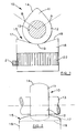
- Figure 1 illustrates in front elevation a cam mechanism formed in accordance with the present invention;
- Figure 2 illustrates in side elevation the cam mechanism shown in Figure 1;
- Figures 3 and 4 illustrate sections of the cam mechanism illustrated in Figure 1, with the cam follower at different orientations to the cam;
- Figure 5 illustrates an alternative form of cam mechanism;
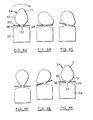
- Figures 6A to 6F show sequential positions of the cam and cam follower illustrated in Figure 5 as the cam rotates;
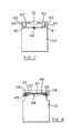
- Figure 7 illustrates a modification to the cam mechanism shown in Figure 5; and
- Figure 8 illustrates an alternative modification to the cam mechanism illustrated in Figure 5.
- The cam mechanism illustrated in Figures 1 to 4 includes a
cam 10 having alobe formation 11 which projects from a basiccircular formation 12. Thecam 10 is mounted on or formed as a part of acamshaft 13, for rotation therewith. Thesurface 14 of thecam 10 engages theend face 15 of abucket follower 16. Thebucket follower 16 is slidingly located perpendicular to the axis of rotation of thecam 10, in a cylindrical bucket guide (not shown) and in the conventional manner would engage the end of the stem of a poppet valve, so that upon rotation of thecam 10, thelobe formation 11 will open and close the poppet valve. - The
end face 15 of thebucket follower 16 is profiled, having a pair offlat surfaces arcuate surface 19, of radius equal to the radius of thecam base circle 12. - The
surface 14 of thecam 10 is radiussed across its width, to a radius equal or smaller than the radius of thecam base circle 12. Thecam 10 can thus engage the profiledface 15 ofbucket follower 16, at any orientation of thebucket follower 16. Means (not shown) is provided for rotation of thebucket follower 16 in its guide, so that orientation of the profiledface 15 thereof, may be varied with respect to thecam 10. This means may be in the form of a rack and pinion mechanism, arack 21 being mounted transversely of thebucket follower 16 and engagingteeth 22 formed thereon, so that axial movement of therack 21 will cause rotation of thebucket follower 16. Axial movement of therack 21 will preferably be controlled by appropriate means in response to the engine speed. - As illustrated in Figure 3, when the
bucket follower 16 is positioned so that the diametricalarcuate surface 19 is perpendicular to the axis of rotation of thecam 10, thecam 10 will engage an effectivelyflat surface 20. In this position, thecam 10 will commence to move thebucket follower 16 and hence begin to open the valve, when the start of the lobe formation 11 (point A) engages theflat surface 20 at point C and will hold the valve open until the end of the lobe formation 11 (point B) engages theflat surface 20 at point C. Thebucket follower 16 will be moved and the valve will consequently be held open for movement of thecam 10 through an angle α. - When the
bucket follower 16 is rotated through 90° so that the diametricalarcuate surface 19 is parallel to the axis of rotation ofcam 10, thecam surface 14 will engage profiledsurface 21. In this position, thecam 10 will begin to move thebucket follower 16 when the start of lobe formation 11 (point A) engages theflat surface 18 at point D and will return to its initial position when the end of the lobe formation (point B) engages theflat surface 17 at point E. Thebucket follower 16 will consequently be moved bylobe formation 11 ofcam 10, and the valve will be held open, for rotation of thecam 10 over an angle α + β. - Duration of movement of the
bucket follower 16 between α and α + β may be achieved by rotating thebucket follower 16, so that theface 15 is orientated at angles intermediate of those illustrated in Figures 3 and 4. Furthermore, the angle of inclination of thesurfaces cam 10 and opening and closing of the valve. - In the cam mechanism illustrated in Figure 5, a
disc 30 is pivotally mounted on theend face 31 of abucket follower 32 on adiametrical pivot 33, the virtual centre of thepivot 33 being at or near theupper surface 30′ of thedisc 30, where it is engaged by acam 34. Theend face 31 ofbucket follower 32 has a pair offlats pivot 33 away fromdisc 30, so as to permit thedisc 30 to seesaw aboutpivot 33. As illustrated in Figures 6A to 6F, when thepivot 33 is aligned so that it is parallel to the axis of rotation of thecam 34, rotation of thecam 34 will cause movement of thebucket follower 32 through the following stages: - 1. When the
cam 34 is running with itsbase circle 12 in engagement with the disc 30 (as illustrated in Figure 6A) thedisc 30 is held normal to the axis of thebucket follower 32 constrained by both thebucket follower 32 and thecam 34, until thelobe formation 11 engages the disc 30 (as illustrated in Figure 6B); - 2. Further rotation of the
cam 34 will causedisc 30 to pivot until it is seated against the inclined face 35 (as illustrated in Figure 6C); - 3. Further rotation of
cam 34 will cause thebucket follower 32 to move downwardly until at its maximum movement the nose oflobe formation 11 will engage thedisc 30 at its virtual centre (as illustrated in Figure 6D); - 4. The
disc 30 will then flip over to engageinclined face 36 and continued rotation of thecam 34 will allow thebucket follower 32 to move upwardly, until it is restored to its original position (as illustrated in Figure 6E); - 5. Continued rotation of the
cam 34 back on itsbase circle diameter 12 will bringdisc 30 back to its initial position (as illustrated in Figure 6F). - The duration of movement of the
bucket follower 32 will consequently correspond to rotation of thecam 34 through angle α - β , where α is the angle subtended by thelobe formation 11 and β is the difference in angles of inclination offaces - If the
bucket follower 32 is now rotated through 90°, so that the axis of rotation ofcam 34 is parallel to thediametrical pivot 33, as thecam 34 rotates againstdisc 30, thedisc 30 will be unable to pivot relative to thebucket follower 32 and consequently thecam 34 will operate against a flat surface in a manner similar to that indicated in Figure 3. The duration of movement of thebucket follower 32 will consequently correspond to rotation of the cam through an angle α. - Also as with the embodiment described with reference to Figures 1 to 4, provided that the
cam surface 14 is radiussed across its width to permit tilting of thedisc 30, durations corresponding to angles intermediate of α and α - β may be achieved by rotating thebucket follower 32, so that thepivot 33 is orientated at intermediate angles. Alternatively, the above mechanism may be operated at only the two extreme positions discussed above, the orientation of the pivot being switched at a selected engine speed. If used in this manner, thecam surface 14 need not be radiussed across its width. - As with the embodiment described with reference to Figures 1 to 4, the angles of inclination of
faces bucket follower 32. Where the bucket followers are rotated, this may also be achieved in a manner similar to that described with reference to Figures 1 to 4. - In the embodiments illustrated in Figures 7 and 8, damping elements control movement of the
pivotted disc 30. The force required to move thebucket follower 32 is proportional to the square of the speed plus an initial pre-set value for seating an associated valve, while the damper elements would produce a force proportional to the speed. The damper elements can thus be arranged at some pre-determined speed, to provide a force greater than that required to move thebucket follower 32, so that at speeds below the pre-determined speed, thebucket follower 32 will not begin to move until thedisc 30 engages theinclined face 35, while above the pre-determined speed, thebucket follower 32 will begin to move whendisc 30 is at some position intermediate of its horizontal position and the position in which it seats against theinclined face 35, thus increasing the duration of movement of thebucket follower 32, without the need to rotate thebucket follower 32. - In the embodiment illustrated in Figure 7, the damping elements are provided by a pair of
pistons 40 which are pivotally attached one on either side of thedisc 30, these pistons engaging incylinders bucket follower 32, thecylinders restrictor 43, so that as thedisc 30 pivots hydraulic fluid in one cylinder will be forced throughrestrictor 43 into the other cylinder to provide a damping action. - In the alternative embodiment illustrated in Figure 8, an
annular rubber seal 45 is provided between thedisc 30 and theend face 15 ofbucket follower 32 to provide a pair offluid chambers disc 30 andend face 15, thesechambers diametrical pivot 33 and being interconnected by a restrictedorifice 48 passing through thepivot 33, so that upon pivotal movement of thedisc 30 hydraulic fluid will be forced from one chamber to the other. A similar effect may be achieved by positioning a ring of suitable elastomeric composition between thedisc 30 and the end face of thebucket follower 32. - In a further embodiment, rather than interconnecting the
cylinders disc 30 and hence the duration of movement of thebucket follower 32 may be controlled to provide a continuous variation without the need to rotate thebucket follower 32. - In conventional cam mechanisms of this type, shims are provided between the
bucket follower 32 and the end of the valve stem in order to adjust the valve clearance. With the embodiments illustrated in Figures 5 to 8 in place of shims, the thickness of thedisc 30 could be varied to provide the required clearance. - While the invention has been described so far with reference to individual cam mechanisms, it is likely that several such mechanisms would be used together. Where the cam mechanisms include rotatable followers, rotation of all the followers may be controlled by a common device, for example rack mechanism. However, it is preferable to rotate the followers when they are engaged by the base circles of the cams. It may consequently be necessary to employ individual or at least two or more common mechanisms for this purpose.
Claims (5)
- A cam mechanism comprising a cam (10;34) of basic circular formation and having a lobe formation (11) extending radially outwardly along part of its periphery; and a cam follower (16;30,32) mounted for reciprocating movement along an axis perpendicular to the axis of rotation of the cam (10;34); the cam (10;34) acting against an end face (15;30') of the cam follower (16;30,32) so that engagement of the lobe formation (11) therewith will cause movement of the cam follower (16;30,32), the end face (15,31) of the cam follower (16;30,32) being profiled, characterised in that means (21,22) are provided for rotating the cam follower (16;30,32) axially to vary the angular orientation of the profiled face (15;31) with respect to the axis of rotation of the cam (10;34) to adjust the angular positions at which the lobe formation engages and disengages the end face and thus the duration of movement of the cam follower.
- A cam mechanism according to Claim 1 characterised in that the end face (15) of the cam follower (16) has a pair of flat surfaces (17,18) inclined outwardly towards the cam (10), said flat surfaces (17,18) being smoothly interconnected by a diametrical arcuate surface (19) of radius equal to the base circle diameter of the cam (10).
- A cam mechanism according to Claim 1 characterised in that a disc (30) is mounted on the end face (31) of the cam follower (32) by means of a diametrical pivot (33), flats (35,36) being provided on the end face (31) of the cam follower (32) inclined from the pivot (33) away from the disc (30).
- A cam mechanism according to any one of Claims 1 to 3 characterised in that the cam follower (16;32) may be rotated to any orientation relative to the cam (10), the cam (10) being radiussed across its width to accommodate varying inclination of the surface (15;30) of the cam follower (16;32) with which it engages.
- A cam mechanism according to Claim 4 characterised in that the cam follower (16;32) may be rotated from one position in which the cam (10) engages an effectively flat surface (20;30') on the cam follower (16;32), to a second position in which the cam (10) is disposed normal to an inclined surface (17,18;35,36) on the cam follower (16;32).
Priority Applications (1)
| Application Number | Priority Date | Filing Date | Title |
|---|---|---|---|
| AT88304256T ATE77675T1 (en) | 1987-05-21 | 1988-05-11 | CAM DEVICES. |
Applications Claiming Priority (2)
| Application Number | Priority Date | Filing Date | Title |
|---|---|---|---|
| GB8711993 | 1987-05-21 | ||
| GB878711993A GB8711993D0 (en) | 1987-05-21 | 1987-05-21 | Cam mechanisms |
Publications (3)
| Publication Number | Publication Date |
|---|---|
| EP0292185A2 EP0292185A2 (en) | 1988-11-23 |
| EP0292185A3 EP0292185A3 (en) | 1989-08-09 |
| EP0292185B1 true EP0292185B1 (en) | 1992-06-24 |
Family
ID=10617680
Family Applications (1)
| Application Number | Title | Priority Date | Filing Date |
|---|---|---|---|
| EP88304256A Expired - Lifetime EP0292185B1 (en) | 1987-05-21 | 1988-05-11 | Cam mechanisms |
Country Status (6)
| Country | Link |
|---|---|
| US (1) | US4869215A (en) |
| EP (1) | EP0292185B1 (en) |
| JP (1) | JPH01187307A (en) |
| AT (1) | ATE77675T1 (en) |
| DE (1) | DE3872311T2 (en) |
| GB (1) | GB8711993D0 (en) |
Cited By (3)
| Publication number | Priority date | Publication date | Assignee | Title |
|---|---|---|---|---|
| WO2005042930A2 (en) | 2003-11-03 | 2005-05-12 | Avl List Gmbh | Internal combustion engine |
| AT413853B (en) * | 2004-03-09 | 2006-06-15 | Avl List Gmbh | Internal combustion engine comprises an actuating element fixed by a blocking piston in its first position defining a first valve stroke, and having a second position that defines a shorter second valve stroke |
| AT414011B (en) * | 2004-02-26 | 2006-08-15 | Avl List Gmbh | Internal combustion engine comprises an actuating element fixed by a blocking piston in its first position defining a first valve stroke, and having a second position that defines a shorter second valve stroke |
Families Citing this family (22)
| Publication number | Priority date | Publication date | Assignee | Title |
|---|---|---|---|---|
| US4995353A (en) * | 1990-04-11 | 1991-02-26 | General Motors Corporation | Valve train with lash/compliance compensation |
| US5231960A (en) * | 1991-06-21 | 1993-08-03 | Ambrose White | Method and appparatus for varying intake and exhaust valve opening and closing in a reciprocating piston engine |
| DE4302877C2 (en) * | 1993-02-02 | 1996-04-11 | Schaeffler Waelzlager Kg | Pestle |
| EP0763165A1 (en) * | 1994-06-02 | 1997-03-19 | Valasopoulos, Christos | Piston internal combustion engine variable action valve lifter system |
| AUPN926596A0 (en) * | 1996-04-16 | 1996-05-09 | Roberts, Frederick William | Valve timing system |
| KR100501461B1 (en) * | 1996-04-16 | 2005-09-09 | 프레더릭 윌리암 로버트 | Valve timing system |
| GB9612178D0 (en) * | 1996-06-11 | 1996-08-14 | Ricardo Consulating Engineers | Hydraulic tappets |
| AUPP139598A0 (en) | 1998-01-19 | 1998-02-05 | D.A.R.U.T. Pty Ltd | Cam and cam followers for engines |
| US6155216A (en) * | 1998-01-26 | 2000-12-05 | Riley; Michael B | Variable valve apparatus |
| US6357406B1 (en) * | 2000-11-22 | 2002-03-19 | Borgwarner Inc. | Variable valve actuation system |
| DE10123966A1 (en) * | 2001-05-17 | 2002-11-21 | Ina Schaeffler Kg | Bucket tappet for valve drive has jacket with appreciably lower height than bucket tappet as whole |
| EP1522683B1 (en) * | 2003-10-06 | 2008-03-05 | Ford Global Technologies, LLC, A subsidary of Ford Motor Company | Valve actuating mechanism |
| US6990935B2 (en) * | 2003-10-27 | 2006-01-31 | Borgwarner Inc. | Pivoting lifter control system using spool valve and check valve to recirculate oil |
| RU2257479C1 (en) * | 2004-02-16 | 2005-07-27 | Рожков Анатолий Павлович | Tappet of valve-actuating cam mechanism |
| JP4647528B2 (en) * | 2005-03-24 | 2011-03-09 | 本田技研工業株式会社 | Valve lifter and manufacturing method thereof |
| US20080149058A1 (en) * | 2005-06-27 | 2008-06-26 | Borgwarner Inc. | Actuator and Control Method For Variable Valve Timing (Vvt) Mechanism |
| US7506624B2 (en) * | 2006-02-28 | 2009-03-24 | Perkins Engines Company Limited | Variable engine valve actuation system |
| RU2325540C2 (en) * | 2006-05-29 | 2008-05-27 | Ильшат Ахматгалиевич Галимов | Cam mechanism of gas engine valve-actuating gear |
| LV13993B (en) * | 2008-02-21 | 2010-01-20 | Motorcikls, Sia | Device for regulating internal combustion gas distribution phases |
| DE102011106395A1 (en) * | 2011-07-02 | 2013-01-03 | Man Truck & Bus Ag | Valve control for at least one valve of an internal combustion engine |
| CN113649881A (en) * | 2021-09-23 | 2021-11-16 | 陈佳佳 | A cam track disc grinder |
| DE102024103382A1 (en) * | 2024-02-07 | 2025-08-07 | Dosmatix Gmbh | Piston dosing device |
Family Cites Families (15)
| Publication number | Priority date | Publication date | Assignee | Title |
|---|---|---|---|---|
| FR326921A (en) * | 1902-12-02 | 1903-06-09 | Johnston John Howard | Regulator for internal combustion engine |
| FR543706A (en) * | 1921-11-19 | 1922-09-08 | Advanced valve lifter or valve lifter for engines | |
| US1501041A (en) * | 1922-01-25 | 1924-07-15 | Henry H Cutler | Internal-combustion engine |
| DE544741C (en) * | 1929-10-17 | 1932-02-22 | Herbert Haentzschel | Reversal for internal combustion engines that work in four-stroke or two-stroke |
| US2663288A (en) * | 1952-09-02 | 1953-12-22 | Loyd F Ashley | Variable timing cam follower |
| US2933949A (en) * | 1957-09-09 | 1960-04-26 | Standard Screw | Tappet face |
| FR1245669A (en) * | 1959-09-26 | 1960-11-10 | Renault | Oscillating valve timing system for internal combustion engine |
| GB1496513A (en) * | 1975-02-03 | 1977-12-30 | Scarrott G | Valve operating mechanisms for internal combustion engine |
| US4205634A (en) * | 1978-02-17 | 1980-06-03 | Tourtelot Edward M Jr | Variable valve timing mechanism |
| JPS5523326A (en) * | 1978-08-04 | 1980-02-19 | Nissan Diesel Motor Co Ltd | Control system for controlling operation of internal combustion engine with torque converter |
| DE2852293C2 (en) * | 1978-12-02 | 1980-12-11 | Bayerische Motoren Werke Ag, 8000 Muenchen | Method and device for preventing the inflation of a hydraulic valve lash adjuster |
| US4261307A (en) * | 1979-09-06 | 1981-04-14 | Sidney Oldberg | Variable valve timing control for internal combustion engines |
| DE2938283A1 (en) * | 1979-09-21 | 1981-04-02 | Audi Nsu Auto Union Ag, 7107 Neckarsulm | Engine cam tappet with recessed shim disc - has flat or incline on cam face for easy disc removal to replace it |
| IT1156204B (en) * | 1982-10-12 | 1987-01-28 | Fiat Auto Spa | TAPPING SYSTEM FOR VERTICAL PROFILE CAMSHAFTS ENGINES |
| JPS62162708A (en) * | 1985-08-23 | 1987-07-18 | Yanmar Diesel Engine Co Ltd | Valve opening and closing timing regulating device for internal combustion engine |
-
1987
- 1987-05-21 GB GB878711993A patent/GB8711993D0/en active Pending
-
1988
- 1988-05-11 EP EP88304256A patent/EP0292185B1/en not_active Expired - Lifetime
- 1988-05-11 AT AT88304256T patent/ATE77675T1/en active
- 1988-05-11 DE DE8888304256T patent/DE3872311T2/en not_active Expired - Lifetime
- 1988-05-20 JP JP63123748A patent/JPH01187307A/en active Pending
- 1988-05-20 US US07/196,931 patent/US4869215A/en not_active Expired - Fee Related
Cited By (3)
| Publication number | Priority date | Publication date | Assignee | Title |
|---|---|---|---|---|
| WO2005042930A2 (en) | 2003-11-03 | 2005-05-12 | Avl List Gmbh | Internal combustion engine |
| AT414011B (en) * | 2004-02-26 | 2006-08-15 | Avl List Gmbh | Internal combustion engine comprises an actuating element fixed by a blocking piston in its first position defining a first valve stroke, and having a second position that defines a shorter second valve stroke |
| AT413853B (en) * | 2004-03-09 | 2006-06-15 | Avl List Gmbh | Internal combustion engine comprises an actuating element fixed by a blocking piston in its first position defining a first valve stroke, and having a second position that defines a shorter second valve stroke |
Also Published As
| Publication number | Publication date |
|---|---|
| DE3872311D1 (en) | 1992-07-30 |
| ATE77675T1 (en) | 1992-07-15 |
| DE3872311T2 (en) | 1992-12-03 |
| GB8711993D0 (en) | 1987-06-24 |
| JPH01187307A (en) | 1989-07-26 |
| EP0292185A3 (en) | 1989-08-09 |
| EP0292185A2 (en) | 1988-11-23 |
| US4869215A (en) | 1989-09-26 |
Similar Documents
| Publication | Publication Date | Title |
|---|---|---|
| EP0292185B1 (en) | Cam mechanisms | |
| US4131096A (en) | Valve timing mechanisms | |
| US4714057A (en) | Variable valve control system for a piston internal-combustion engine | |
| US3641988A (en) | Valve-actuating mechanism for an internal combustion engine | |
| EP0311282B1 (en) | Valve mechanisms | |
| US7469669B2 (en) | Variable valve train mechanism of internal combustion engine | |
| GB2292233A (en) | Valve duration control system for four-cycle engine | |
| US4870872A (en) | Cam mechanisms | |
| GB2054036A (en) | Valve operating mechansim for internal combustion engines | |
| US6659053B1 (en) | Fully variable valve train | |
| JP3355225B2 (en) | Intake and exhaust valve drive control device for internal combustion engine | |
| EP0070901A1 (en) | Engine camshaft for variably controlling valve operation | |
| EP1243765A1 (en) | Internal combustion engine with variable valve lift | |
| JPS6213708A (en) | Multicylinder internal-combustion engine | |
| JPS61149512A (en) | Variable valve timing device | |
| JP2808745B2 (en) | Engine Valve Actuator | |
| JPS6213709A (en) | Multicylinder internal-combustion engine | |
| JPS62174513A (en) | Intake pipe control valve | |
| JPS6193217A (en) | Variable valve unit of four-cycle engine | |
| JPS6210411A (en) | Lift control device for intake/exhaust valve of internal combustion engine | |
| JPH0326246Y2 (en) | ||
| JPS61201804A (en) | Internal combustion engine valve train | |
| JPH0151885B2 (en) | ||
| JPS58220910A (en) | Tappet valve apparatus of internal-combustion engine | |
| JPS6135683Y2 (en) |
Legal Events
| Date | Code | Title | Description |
|---|---|---|---|
| PUAI | Public reference made under article 153(3) epc to a published international application that has entered the european phase |
Free format text: ORIGINAL CODE: 0009012 |
|
| AK | Designated contracting states |
Kind code of ref document: A2 Designated state(s): AT BE CH DE ES FR GB GR IT LI LU NL SE |
|
| PUAL | Search report despatched |
Free format text: ORIGINAL CODE: 0009013 |
|
| AK | Designated contracting states |
Kind code of ref document: A3 Designated state(s): AT BE CH DE ES FR GB GR IT LI LU NL SE |
|
| 17P | Request for examination filed |
Effective date: 19891018 |
|
| 17Q | First examination report despatched |
Effective date: 19910201 |
|
| GRAA | (expected) grant |
Free format text: ORIGINAL CODE: 0009210 |
|
| AK | Designated contracting states |
Kind code of ref document: B1 Designated state(s): AT BE CH DE ES FR GB GR IT LI LU NL SE |
|
| PG25 | Lapsed in a contracting state [announced via postgrant information from national office to epo] |
Ref country code: NL Effective date: 19920624 Ref country code: LI Effective date: 19920624 Ref country code: GR Free format text: LAPSE BECAUSE OF FAILURE TO SUBMIT A TRANSLATION OF THE DESCRIPTION OR TO PAY THE FEE WITHIN THE PRESCRIBED TIME-LIMIT Effective date: 19920624 Ref country code: ES Free format text: THE PATENT HAS BEEN ANNULLED BY A DECISION OF A NATIONAL AUTHORITY Effective date: 19920624 Ref country code: CH Effective date: 19920624 Ref country code: BE Effective date: 19920624 Ref country code: AT Effective date: 19920624 |
|
| REF | Corresponds to: |
Ref document number: 77675 Country of ref document: AT Date of ref document: 19920715 Kind code of ref document: T |
|
| REF | Corresponds to: |
Ref document number: 3872311 Country of ref document: DE Date of ref document: 19920730 |
|
| ET | Fr: translation filed | ||
| ITF | It: translation for a ep patent filed | ||
| REG | Reference to a national code |
Ref country code: CH Ref legal event code: PL |
|
| NLV1 | Nl: lapsed or annulled due to failure to fulfill the requirements of art. 29p and 29m of the patents act | ||
| PLBE | No opposition filed within time limit |
Free format text: ORIGINAL CODE: 0009261 |
|
| STAA | Information on the status of an ep patent application or granted ep patent |
Free format text: STATUS: NO OPPOSITION FILED WITHIN TIME LIMIT |
|
| PG25 | Lapsed in a contracting state [announced via postgrant information from national office to epo] |
Ref country code: LU Free format text: LAPSE BECAUSE OF NON-PAYMENT OF DUE FEES Effective date: 19930531 |
|
| 26N | No opposition filed | ||
| EAL | Se: european patent in force in sweden |
Ref document number: 88304256.6 |
|
| PGFP | Annual fee paid to national office [announced via postgrant information from national office to epo] |
Ref country code: FR Payment date: 19950410 Year of fee payment: 8 |
|
| PGFP | Annual fee paid to national office [announced via postgrant information from national office to epo] |
Ref country code: SE Payment date: 19950418 Year of fee payment: 8 |
|
| PGFP | Annual fee paid to national office [announced via postgrant information from national office to epo] |
Ref country code: GB Payment date: 19950420 Year of fee payment: 8 |
|
| PGFP | Annual fee paid to national office [announced via postgrant information from national office to epo] |
Ref country code: DE Payment date: 19950421 Year of fee payment: 8 |
|
| PG25 | Lapsed in a contracting state [announced via postgrant information from national office to epo] |
Ref country code: GB Effective date: 19960511 |
|
| PG25 | Lapsed in a contracting state [announced via postgrant information from national office to epo] |
Ref country code: SE Effective date: 19960512 |
|
| GBPC | Gb: european patent ceased through non-payment of renewal fee |
Effective date: 19960511 |
|
| PG25 | Lapsed in a contracting state [announced via postgrant information from national office to epo] |
Ref country code: FR Effective date: 19970131 |
|
| PG25 | Lapsed in a contracting state [announced via postgrant information from national office to epo] |
Ref country code: DE Effective date: 19970201 |
|
| EUG | Se: european patent has lapsed |
Ref document number: 88304256.6 |
|
| REG | Reference to a national code |
Ref country code: FR Ref legal event code: ST |
|
| PG25 | Lapsed in a contracting state [announced via postgrant information from national office to epo] |
Ref country code: IT Free format text: LAPSE BECAUSE OF NON-PAYMENT OF DUE FEES Effective date: 20050511 |