EP0292008A2 - Method of and system for driving magnetic tape - Google Patents
Method of and system for driving magnetic tape Download PDFInfo
- Publication number
- EP0292008A2 EP0292008A2 EP88108146A EP88108146A EP0292008A2 EP 0292008 A2 EP0292008 A2 EP 0292008A2 EP 88108146 A EP88108146 A EP 88108146A EP 88108146 A EP88108146 A EP 88108146A EP 0292008 A2 EP0292008 A2 EP 0292008A2
- Authority
- EP
- European Patent Office
- Prior art keywords
- magnetic tape
- oscillator
- tape
- wave
- traveling
- Prior art date
- Legal status (The legal status is an assumption and is not a legal conclusion. Google has not performed a legal analysis and makes no representation as to the accuracy of the status listed.)
- Granted
Links
Images

Classifications
-
- G—PHYSICS
- G11—INFORMATION STORAGE
- G11B—INFORMATION STORAGE BASED ON RELATIVE MOVEMENT BETWEEN RECORD CARRIER AND TRANSDUCER
- G11B15/00—Driving, starting or stopping record carriers of filamentary or web form; Driving both such record carriers and heads; Guiding such record carriers or containers therefor; Control thereof; Control of operating function
- G11B15/60—Guiding record carrier
-
- G—PHYSICS
- G11—INFORMATION STORAGE
- G11B—INFORMATION STORAGE BASED ON RELATIVE MOVEMENT BETWEEN RECORD CARRIER AND TRANSDUCER
- G11B15/00—Driving, starting or stopping record carriers of filamentary or web form; Driving both such record carriers and heads; Guiding such record carriers or containers therefor; Control thereof; Control of operating function
- G11B15/18—Driving; Starting; Stopping; Arrangements for control or regulation thereof
- G11B15/26—Driving record carriers by members acting directly or indirectly thereon
-
- G—PHYSICS
- G11—INFORMATION STORAGE
- G11B—INFORMATION STORAGE BASED ON RELATIVE MOVEMENT BETWEEN RECORD CARRIER AND TRANSDUCER
- G11B15/00—Driving, starting or stopping record carriers of filamentary or web form; Driving both such record carriers and heads; Guiding such record carriers or containers therefor; Control thereof; Control of operating function
- G11B15/18—Driving; Starting; Stopping; Arrangements for control or regulation thereof
- G11B15/40—Driving record carriers otherwise than by electric motor
-
- G—PHYSICS
- G11—INFORMATION STORAGE
- G11B—INFORMATION STORAGE BASED ON RELATIVE MOVEMENT BETWEEN RECORD CARRIER AND TRANSDUCER
- G11B15/00—Driving, starting or stopping record carriers of filamentary or web form; Driving both such record carriers and heads; Guiding such record carriers or containers therefor; Control thereof; Control of operating function
- G11B15/60—Guiding record carrier
- G11B15/61—Guiding record carrier on drum, e.g. drum containing rotating heads
Definitions
- a tape guide 63 is provided with a pair of tape driving systems 62A and 62B so that the magnetic tape 4 is pressed against the tape driving systems 62A and 62B.
- the tape driving systems 62A and 62B may be like those described above in conjunction with Figures 2 to 4 or may be as shown in Figure 12 which will be described later.
- the tape driving systems 62A 62B are respectively oriented to move the tape 4 obliquely upwardly and downwardly as shown by arrows B with respect to the running direction of the magnetic tape shown by arrow A.
- the tape driving systems 62A and 62B are selectively energized to move upward or downward the magnetic tape 4 under the control of an output signal of a tape position detecting means (not shown) which detects the transverse position of the magnetic tape 4.
- the magnetic tape is not subjected to strong local tension since the magnetic tape is run by way of surface-to-surface contact of the oscillater and the magnetic tape, and accordingly, the magnetic tape cannot be stretched or twisted to adversely affect running of the tape even if the magnetic tape is very thin.
- the motor for driving the capstan required in the conventional tape driving system can be eliminated and the position of the tape driving system can be freely selected, the overall tape driving system can be further reduced in size and weight.
- the tape driving system in accordance with the present invention is advantageous over the conventional tape driving systems in that the magnetic tape can be run with a high accuracy better than 1 ⁇ m and with an excellent response.
Landscapes
- General Electrical Machinery Utilizing Piezoelectricity, Electrostriction Or Magnetostriction (AREA)
- Adjustment Of The Magnetic Head Position Track Following On Tapes (AREA)
Abstract
Description
- This invention relates to a method of and a system for driving a magnetic tape which are particularly suitable for driving a thin magnetic tape.
- As is well known, in a videotape recorder or an audiotape recorder, the magnetic tape is conventionally run by a capstan and a pinch roller rotated at a constant speed. However, when a thin magnetic tape such as a long-playing tape is driven by such a driving system, the magnetic tape is apt to twist or meander to adversely affect running of the tape, or is sometimes stretched by tension, thereby making it impossible to effect accurate tracking.
- In view of the foregoing observations and description, the primary object of the present invention is to provide a novel method of and a novel system for driving a magnetic tape which is free from the aforesaid drawbacks inherent to the conventional driving system comprising the capstan and the pinch roller.
- In accordance with the present invention, a unidirectional traveling-surface-wave by ultrasonic oscillation is generated on a surface of an oscillator, and a magnetic tape is run in the direction opposite to the traveling direction of the surface wave by pressing the surface of the oscillator against a surface of the magnetic tape. As the oscillator, an electrostrictor or a magnetostrictor is used.
- That is, in the present invention, the principle of an ultrasonic motor which generates a surface wave (flexure vibration) by ultrasonic oscillation by the use of an electrostrictor or a magnetostrictor is applied. As for the ultrasonic motor, see, for instance, "Applied Physics", pp.65 - 66, No. 6, Vol. 54, 1985, "Nikkei Mechanical", p. 40, No. 24, March, 1986, "Nikkei Electronics", pp. 90 - 92, No. 24, March, 1986, and "Nikkei Electronics", pp. 86 - 87, No. 9, March, 1987.
- In accordance with the principle, numbers of wave peaks of the surface wave generated on the surface of the oscillator make ultrasonic oscillation while generating ellipsoidal loci and moves a movable member on the surface in the direction opposite to the traveling direction of the surface wave by friction. In the present invention, the magnetic tape is driven by bringing the oscillator having such a surface wave into surface-to-surface contact with the magnetic tape.
- In the tape driving system of the present invention, the oscillator to be brought into contact with the magnetic tape may be caused to oscillate by transmitting vibration from a plurality of oscillating elements which are applied with high frequency voltages with phases different from each other by 90° or 120°, or may be directly formed of a plurality of contiguously arranged piezo-electric elements which are arranged so that traveling waves are generated on the surface of the piezo-electric elements when alternating voltages with different phases are applied to alternate piezo-electric elements.
- In one preferred embodiment of the present invention, the transverse position of the magnetic tape is regulated by generating a unidirectional traveling-surface-wave by ultrasonic oscillation on a surface of an oscillator, and pressing the surface of the oscillator against a surface of the magnetic tape so that the traveling direction of the surface wave has a component directed in the transverse direction of the magnetic tape.
-
- Figure 1 is a schematic view showing a tape running system for a videotape recording and reproducing system provided with a tape driving system in accordance with the present invention,
- Figure 2A is a schematic plan view showing a tape driving system in accordance with an embodiment of the present invention,
- Figure 2B is a side view of the tape driving system of Figure 2A,
- Figure 3 is a schematic perspective view showing a tape driving system in accordance with another embodiment of the present invention,
- Figure 4 is a schematic side view showing a tape driving system in accordance with still another embodiment of the present invention,
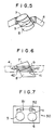
- Figure 5 is a schematic perspective view for illustrating a tape driving system in accordance with still another embodiment of the present invention,
- Figure 6 is a schematic side view for illustrating a modification of the embodiment shown in Figure 5,
- Figure 7 is a schematic plan view showing an audiotape recording and reproducing system provided with a tape driving system in accordance with the present invention,
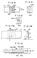
- Figures 8, 9 10 and 11A are schematic views for illustrating various embodiments of a system for regulating the transverse position of the magnetic tape,
- Figure 11B is a side view of Figure 11A, and
- Figure 12 is a schematic view showing an example of the tape driving system which can employed in the systems shown in Figures 8 to 11A.
- In Figure 1, a
videotape 4 is unrolled from asupply reel 6 and taken up by a take-up reel 5. Thevideotape 4 is driven by first and secondtape driving systems 1 and 2 in accordance with an embodiment of the present invention respectively disposed downstream and upstream of arotary drum 3 having a magnetic head (not shown). The first tape driving system 1 downstream of therotary drum 3 is for accurately running themagnetic tape 4 with respect to therotary drum 3, and the secondtape driving system 2 upstream of therotary drum 3 is for applying back tension to themagnetic tape 4. As in the conventional videotape recording system, the take-up reel 5 is driven to take up themagnetic tape 4, while thesupply reel 6 is arranged to apply light back tension to themagnetic tape 4. - Each of the first and second
tape driving systems 1 and 2 comprises, as shown in Figures 2A and 2B, a piezo-electric element row formed of a plurality of piezo-electric element pairs, each pair comprising first and second piezo-electric elements support 10 contiguously with each other. The piezo-electric element pairs are arranged so that the first and second piezo-electric elements electric elements electric elements magnetic tape 4 against the surface of the piezo-electric element row, themagnetic tape 4 is run in the direction opposite to the traveling direction of the surface waves as described above. - Figure 3 shows another embodiment of the present invention. The tape driving system of this embodiment comprises piezo-
electric elements 21 fixed on one side of anelastic body 20. In this embodiment, by causing theelastic body 20 to make high frequency oscillation by the piezo-electric elements 21, thereby generating unidirectional traveling waves on the other side of theelastic body 20, and pressing themagnetic tape 4 against said the other side of theelastic body 20, themagnetic tape 4 is run. - Figure 4 shows still another embodiment of the present invention. The tape driving system of this embodiment comprises a pair of
oscillators elastic body 30 at opposite ends of theelastic body 30. Theoscillators elastic body 30 to make high frequency oscillations which differ from each other in phase by 90°. Further, a vibration absorber 33 is connected to one end of theelastic body 30 to prevent generation of reflected waves at one end of theelastic body 30 which can cause the oscillation of theelastic body 30 to act as stationary wave as a whole. - In still another embodiment of the present invention shown in Figure 5, the tape driving systems in accordance with the present invention are directly provided on a pair of
cylinders cylinders cylinder 7 and thecylinder 8 is stationary. In this case, a piezo-electric element row like that described above is provided at least a part of the surface of thestationary cylinder 8 along which themagnetic tape 4 is run. In the case that both thecylinders 7′ and 8′ are stationary with the rotary magnetic head 9 intervening therebetween as shown in Figure 6, piezo-electric element groups cylinders 7′ and 8′, respectively. Each of the piezo-electric element groups electric element rows 42 contiguously arranged in the direction perpendicular to the running direction of themagnetic tape 4. Each of the piezo-electric element rows 42 comprises a plurality of piezo-electric element pairs which are like those described above in conjunction with Figures 2A and 2B and arranged in the running direction of themagnetic tape 4 to generate surface waves in the longitudinal direction of the row, though the individual piezo-electric elements are not shown. - Figure 7 shows still another embodiment in which the present invention is applied to an
audiotape cassette 50. A pair oftape driving systems magnetic tape 4. The tape driving forces of thetape driving systems tape 4 by virtue of the difference in the driving force. - In the case that the tape driving system of the present invention is applied to a videotape recording and reproducing system, the frequency of the oscillation of the tape driving system is preferably a multiple of a frequency corresponding to the number of horizontal scanning lines of a TV system. The term "multiple" should be interpreted to include "one-fold". That is, the frequency of the oscillation of the tape driving system may be equal to a frequency corresponding to the number of horizontal scanning lines of the TV system.
- That is, an oscillator such as an electrostrictor or a magnetostrictor is generally oscillated at a resonance frequency which depends on the material of the element, the size of the element and the like. However, such a frequency can adversely affect the recording signal or the reproducing signal of the videotape recording and reproducing system to generate noise and/or fricker in a reproduced image. As will be apparent to those skilled in the art, when the frequency of the oscillation of the tape driving system is a multiple of a frequency corresponding to the number of horizontal scanning lines of the TV system used in the videotape recording and reproducing system, influence of the oscillation of the tape driving system on the image signals can be easily removed, and at the same time, the frequency of the driving power of the tape driving system can be easily obtained from the frequency used in the videotape recording and reproducing system.
- For example, in the case of a NTSC TV system, the frequency of the oscillation of the tape driving system is preferred to be a multiple of 15.75KHz, i.e., 262.5 x 2(fields) x 30(frames).
- The aforesaid principle can be applied in order to regulate position of the magnetic tape in the transverse direction. That is, conventionally, position of the magnetic tape is transversely regulated by a mechanical guiding member such as a flanged roller, a drum like pole or the like. However, as the thickness of the magnetic tape becomes smaller, it becomes more difficult to mechanically regulate position of the tape in the transverse direction by means of such a conventional guiding member.
- That is, by generating a unidirectional traveling-surface-wave by ultrasonic oscillation on a surface of an oscillator, and pressing the surface of the oscillator against a surface of the magnetic tape so that the traveling direction of the surface wave has a component directed in the transverse direction of the magnetic tape, position of the magnetic tape can be regulated in the transverse direction.
- For example, by providing a pair of oscillators so that the traveling directions of the surface waves generated on the surfaces of the respective oscillators have components which are directed in the transverse direction of the magnetic tape and are opposite to each other, and selectively driving one of the oscillators, transverse position of the magnetic tape can be regulated. Otherwise, transverse position of the magnetic tape may be regulated in one direction by an oscillator while the magnetic tape is normally urged in the other direction by other suitable means such as an inclined surface.
- In Figure 8, a
tape guide 63 is provided with a pair oftape driving systems magnetic tape 4 is pressed against thetape driving systems tape driving systems tape 62B are respectively oriented to move thedriving systems 62Atape 4 obliquely upwardly and downwardly as shown by arrows B with respect to the running direction of the magnetic tape shown by arrow A. Thetape driving systems magnetic tape 4 under the control of an output signal of a tape position detecting means (not shown) which detects the transverse position of themagnetic tape 4. - The
tape driving system magnetic tape 4 upward and downward in perpendicular to the running direction of themagnetic tape 4 as shown in Figure 9. Though, in the embodiment shown in Figure 9, thetape driving system 62A is positioned on the upper portion of thetape guide 3 while thetape driving system 62B is positioned on the lower portion of thetape guide 3, thetape driving systems - In the embodiments shown in Figures 8 to 10, when both the
driving systems magnetic tape 4 is not moved in the transverse direction thereof. On the other hand, when only one of thedriving systems driving systems magnetic tape 4 is moved in the direction in which the driving force of said one of thedriving systems - In another embodiment shown in Figures 11A and 11B, a single
tape driving system 65 is supported on an inclined surface of atape guide 64 so that themagnetic tape 4 is urged in the direction shown by arrow C in Figure 11A by virtue of the inclined surface of thetape guide 64. Thetape driving system 65 is energized to exert a driving force in the direction shown by arrow D which is equally balanced with the urging force provided in the direction of the arrow C by the inclined surface of thetape guide 64. The driving force of the drivingsystem 65 is adjusted under the control of an output signal of a tape position detecting means (not shown) which detects the transverse position of themagnetic tape 4. - The tape driving system shown in Figure 12 comprises a plurality of
electrostrictors electrostrictors long electrode 68 at respective one ends and are respectively opposed to separate electrodes 67 67B at respective the other ends. The electrodes 67 connected to an alternating electric source 69 and theelectrodes 67B are connected to another alternatingelectric source 70. When theelectrodes electrostrictors - As can be understood from the description above, in the tape driving system of the present invention, the magnetic tape is not subjected to strong local tension since the magnetic tape is run by way of surface-to-surface contact of the oscillater and the magnetic tape, and accordingly, the magnetic tape cannot be stretched or twisted to adversely affect running of the tape even if the magnetic tape is very thin. Further, since the motor for driving the capstan required in the conventional tape driving system can be eliminated and the position of the tape driving system can be freely selected, the overall tape driving system can be further reduced in size and weight. Further, the tape driving system in accordance with the present invention is advantageous over the conventional tape driving systems in that the magnetic tape can be run with a high accuracy better than 1 µm and with an excellent response.
Claims (10)
Priority Applications (1)
| Application Number | Priority Date | Filing Date | Title |
|---|---|---|---|
| EP94114464A EP0632439B1 (en) | 1987-05-22 | 1988-05-20 | Method of and system for driving magnetic tape |
Applications Claiming Priority (6)
| Application Number | Priority Date | Filing Date | Title |
|---|---|---|---|
| JP12558187A JPS63291248A (en) | 1987-05-22 | 1987-05-22 | Method and device for driving tape |
| JP12558387A JP2608409B2 (en) | 1987-05-22 | 1987-05-22 | Tape drive method |
| JP125583/87 | 1987-05-22 | ||
| JP125582/87 | 1987-05-22 | ||
| JP12558287A JPH0817006B2 (en) | 1987-05-22 | 1987-05-22 | Running tape position control method and device |
| JP125581/87 | 1987-05-22 |
Related Child Applications (2)
| Application Number | Title | Priority Date | Filing Date |
|---|---|---|---|
| EP94114464A Division EP0632439B1 (en) | 1987-05-22 | 1988-05-20 | Method of and system for driving magnetic tape |
| EP94114464.4 Division-Into | 1994-09-14 |
Publications (3)
| Publication Number | Publication Date |
|---|---|
| EP0292008A2 true EP0292008A2 (en) | 1988-11-23 |
| EP0292008A3 EP0292008A3 (en) | 1990-09-19 |
| EP0292008B1 EP0292008B1 (en) | 1995-03-29 |
Family
ID=27315159
Family Applications (2)
| Application Number | Title | Priority Date | Filing Date |
|---|---|---|---|
| EP94114464A Expired - Lifetime EP0632439B1 (en) | 1987-05-22 | 1988-05-20 | Method of and system for driving magnetic tape |
| EP88108146A Expired - Lifetime EP0292008B1 (en) | 1987-05-22 | 1988-05-20 | Method of and system for driving magnetic tape |
Family Applications Before (1)
| Application Number | Title | Priority Date | Filing Date |
|---|---|---|---|
| EP94114464A Expired - Lifetime EP0632439B1 (en) | 1987-05-22 | 1988-05-20 | Method of and system for driving magnetic tape |
Country Status (3)
| Country | Link |
|---|---|
| US (1) | US4875610A (en) |
| EP (2) | EP0632439B1 (en) |
| DE (2) | DE3853445T2 (en) |
Cited By (4)
| Publication number | Priority date | Publication date | Assignee | Title |
|---|---|---|---|---|
| EP0595426A1 (en) * | 1992-10-28 | 1994-05-04 | Nikon Corporation | Ultrasonic actuator |
| EP0599630A2 (en) * | 1992-11-25 | 1994-06-01 | Nippon Hoso Kyokai | Head drum apparatus |
| EP0601671A1 (en) * | 1992-12-11 | 1994-06-15 | Nikon Corporation | Ultrasonic actuator |
| EP0678861A2 (en) * | 1994-04-20 | 1995-10-25 | Canon Kabushiki Kaisha | Optical information recording and/or reproducing apparatus and method with vibration wave driving device or vibration driven motor device |
Families Citing this family (6)
| Publication number | Priority date | Publication date | Assignee | Title |
|---|---|---|---|---|
| JP2712501B2 (en) * | 1989-03-06 | 1998-02-16 | ソニー株式会社 | Tape guide device |
| JP2794894B2 (en) * | 1990-04-19 | 1998-09-10 | ソニー株式会社 | Tape guide device |
| JP3114221B2 (en) * | 1991-03-29 | 2000-12-04 | ソニー株式会社 | Magnetic tape device and tape guide method |
| JPH04311858A (en) * | 1991-04-10 | 1992-11-04 | Sony Corp | Tape guiding device |
| JPH0540997A (en) * | 1991-08-08 | 1993-02-19 | Sony Corp | Tape guide device |
| EP1579223A2 (en) * | 2002-12-23 | 2005-09-28 | Roche Diagnostics GmbH | Transport device for transporting test strips in an analysis system |
Citations (7)
| Publication number | Priority date | Publication date | Assignee | Title |
|---|---|---|---|---|
| SU670974A1 (en) * | 1975-05-29 | 1979-06-30 | Р. Н. Кулагин и Я. Ш. Флейтман | Magnetic tape moving device |
| SU732995A1 (en) * | 1977-10-31 | 1980-05-05 | Азербайджанский Политехнический Институт Им. Ч.Ильдрыма | Device for displacing tape record carrier |
| SU733000A1 (en) * | 1978-10-20 | 1980-05-05 | Азербайджанский Политехнический Институт Им. Ч.Ильдрыма | Tape transport device |
| FR2522216A1 (en) * | 1982-02-25 | 1983-08-26 | Toshiiku Sashida | MOTOR DEVICE USING ULTRASONIC OSCILLATION |
| JPS58196653A (en) * | 1982-05-11 | 1983-11-16 | Matsushita Electric Ind Co Ltd | Magnetic tape guide device |
| JPS60113350A (en) * | 1983-11-22 | 1985-06-19 | Olympus Optical Co Ltd | Tape guide post |
| JPS63193359A (en) * | 1987-02-06 | 1988-08-10 | Hitachi Ltd | Recording medium driving device |
Family Cites Families (3)
| Publication number | Priority date | Publication date | Assignee | Title |
|---|---|---|---|---|
| CH619398A5 (en) * | 1977-04-14 | 1980-09-30 | Bobst Fils Sa J | |
| JPS5492307A (en) * | 1977-12-29 | 1979-07-21 | Sony Corp | Driving circuit of electrostrictive converter |
| JPS56153527A (en) * | 1980-04-12 | 1981-11-27 | Hitachi Denshi Ltd | Piezoelectric bimorph type transducer |
-
1988
- 1988-05-20 US US07/196,522 patent/US4875610A/en not_active Expired - Lifetime
- 1988-05-20 DE DE3853445T patent/DE3853445T2/en not_active Expired - Lifetime
- 1988-05-20 EP EP94114464A patent/EP0632439B1/en not_active Expired - Lifetime
- 1988-05-20 DE DE3856235T patent/DE3856235T2/en not_active Expired - Lifetime
- 1988-05-20 EP EP88108146A patent/EP0292008B1/en not_active Expired - Lifetime
Patent Citations (7)
| Publication number | Priority date | Publication date | Assignee | Title |
|---|---|---|---|---|
| SU670974A1 (en) * | 1975-05-29 | 1979-06-30 | Р. Н. Кулагин и Я. Ш. Флейтман | Magnetic tape moving device |
| SU732995A1 (en) * | 1977-10-31 | 1980-05-05 | Азербайджанский Политехнический Институт Им. Ч.Ильдрыма | Device for displacing tape record carrier |
| SU733000A1 (en) * | 1978-10-20 | 1980-05-05 | Азербайджанский Политехнический Институт Им. Ч.Ильдрыма | Tape transport device |
| FR2522216A1 (en) * | 1982-02-25 | 1983-08-26 | Toshiiku Sashida | MOTOR DEVICE USING ULTRASONIC OSCILLATION |
| JPS58196653A (en) * | 1982-05-11 | 1983-11-16 | Matsushita Electric Ind Co Ltd | Magnetic tape guide device |
| JPS60113350A (en) * | 1983-11-22 | 1985-06-19 | Olympus Optical Co Ltd | Tape guide post |
| JPS63193359A (en) * | 1987-02-06 | 1988-08-10 | Hitachi Ltd | Recording medium driving device |
Non-Patent Citations (6)
| Title |
|---|
| PATENT ABSTRACTS OF JAPAN vol. 12, no. 477 (P-800)(3324) 14 December 1988, & JP-A-63 193359 (HITACHI LTD) 10 August 1988, * |
| PATENT ABSTRACTS OF JAPAN vol. 8, no. 45 (P-257)(1482) 28 February 1984, & JP-A-58 196653 (MATSUSHITA DENKI SANGYO K.K.) 16 November 1983, * |
| PATENT ABSTRACTS OF JAPAN vol. 9, no. 265 (P-399)(1988) 23 October 1985, & JP-A-60 113350 (OLYMPUS KOGAKU KOGYO K.K.) 19 June 1985, * |
| Soviet Inventions Illustrated, Derwent Publications Ltd, Section Electrical Week C11, abstract no.C4329, R34, 23 April 1980 & SU-A-670974 (KULAGIN R N) 30 june 1979 * |
| Soviet Inventions Illustrated, Derwent Publications Ltd, Section Electrical Week D02, abstract no.A1670, T03, 18/02/1981 & SU-A-732995 (AZERB POLY) 15 May 1980 * |
| Soviet Inventions Illustrated, Derwent Publications Ltd, Section Electrical Week D02, abstract no.A1675, T03, 18/02/1981 & SU-A-733000 (AZERB POLY) 15 May 1980 * |
Cited By (13)
| Publication number | Priority date | Publication date | Assignee | Title |
|---|---|---|---|---|
| US5404065A (en) * | 1992-10-28 | 1995-04-04 | Nikon Corporation | Ultrasonic actuator |
| EP0595426A1 (en) * | 1992-10-28 | 1994-05-04 | Nikon Corporation | Ultrasonic actuator |
| US5463506A (en) * | 1992-11-25 | 1995-10-31 | Nippon Hoso Kyokai | Head drum apparatus |
| EP0599630A2 (en) * | 1992-11-25 | 1994-06-01 | Nippon Hoso Kyokai | Head drum apparatus |
| EP0599630A3 (en) * | 1992-11-25 | 1995-01-11 | Japan Broadcasting Corp | Head drum apparatus. |
| EP0601671A1 (en) * | 1992-12-11 | 1994-06-15 | Nikon Corporation | Ultrasonic actuator |
| US5397955A (en) * | 1992-12-11 | 1995-03-14 | Nikon Corporation | Ultrasonic actuator |
| EP0678861A2 (en) * | 1994-04-20 | 1995-10-25 | Canon Kabushiki Kaisha | Optical information recording and/or reproducing apparatus and method with vibration wave driving device or vibration driven motor device |
| EP0678861A3 (en) * | 1994-04-20 | 1996-05-01 | Canon Kk | Optical information recording and/or reproducing apparatus and method with vibration wave driving device or vibration driven motor device. |
| US5805540A (en) * | 1994-04-20 | 1998-09-08 | Canon Kabushiki Kaisha | Optical information recording and/or reproducing apparatus and method with vibration wave driving device or vibration driven motor device |
| US5990596A (en) * | 1994-04-20 | 1999-11-23 | Canon Kabushiki Kaisha | Optical information recording and/or reproducing apparatus and method with vibration wave driving device or vibration driven motor device |
| EP0975028A2 (en) * | 1994-04-20 | 2000-01-26 | Canon Kabushiki Kaisha | Vibration driven motor |
| EP0975028A3 (en) * | 1994-04-20 | 2000-04-12 | Canon Kabushiki Kaisha | Vibration driven motor |
Also Published As
| Publication number | Publication date |
|---|---|
| EP0632439B1 (en) | 1998-08-12 |
| DE3856235D1 (en) | 1998-09-17 |
| EP0632439A3 (en) | 1996-01-31 |
| EP0292008A3 (en) | 1990-09-19 |
| DE3856235T2 (en) | 1998-12-24 |
| DE3853445D1 (en) | 1995-05-04 |
| EP0292008B1 (en) | 1995-03-29 |
| DE3853445T2 (en) | 1995-07-27 |
| US4875610A (en) | 1989-10-24 |
| EP0632439A2 (en) | 1995-01-04 |
Similar Documents
| Publication | Publication Date | Title |
|---|---|---|
| US4151569A (en) | Positionable transducer mounting structure using a piezoelectric bender element | |
| CA1129090A (en) | Automatic scan tracking | |
| US4099211A (en) | Positionable transducing mounting structure and driving system therefor | |
| US4410918A (en) | Helical scan VTR with deflectable head | |
| CA1125909A (en) | Transducer assembly vibration sensor | |
| CA1252205A (en) | Method and apparatus for producing special motion effects in video recording and reproducing apparatus | |
| US4875610A (en) | Method of and system for driving magnetic tape | |
| US4366515A (en) | Automatic head height control apparatus | |
| GB1592377A (en) | Signal reproducing apparatus | |
| EP0599630B1 (en) | Head drum apparatus | |
| US2926219A (en) | Method and apparatus for making duplicate magnetic records | |
| JPS63291249A (en) | Tape driving method | |
| JP2555701B2 (en) | Auto tracking controller | |
| JPS63291248A (en) | Method and device for driving tape | |
| JPH03185660A (en) | Tracking guide post device | |
| JPS63306562A (en) | Tape traveling guide device | |
| JPS58196653A (en) | Magnetic tape guide device | |
| JPS63204575A (en) | Tape cassette and tape traveling mechanism | |
| JPH0817006B2 (en) | Running tape position control method and device | |
| JPH0628635A (en) | Magnetic head | |
| JPH04311856A (en) | Recording and reproducing device | |
| JPH09282736A (en) | Tape driving device | |
| JPH0677291B2 (en) | Magnetic reproducing device | |
| JPH0319118A (en) | Magnetic head device | |
| JPH1091733A (en) | Magnetic medium reader |
Legal Events
| Date | Code | Title | Description |
|---|---|---|---|
| PUAI | Public reference made under article 153(3) epc to a published international application that has entered the european phase |
Free format text: ORIGINAL CODE: 0009012 |
|
| AK | Designated contracting states |
Kind code of ref document: A2 Designated state(s): DE GB NL |
|
| PUAL | Search report despatched |
Free format text: ORIGINAL CODE: 0009013 |
|
| RHK1 | Main classification (correction) |
Ipc: G11B 15/40 |
|
| AK | Designated contracting states |
Kind code of ref document: A3 Designated state(s): DE GB NL |
|
| 17P | Request for examination filed |
Effective date: 19901214 |
|
| 17Q | First examination report despatched |
Effective date: 19920513 |
|
| GRAA | (expected) grant |
Free format text: ORIGINAL CODE: 0009210 |
|
| AK | Designated contracting states |
Kind code of ref document: B1 Designated state(s): DE GB NL |
|
| XX | Miscellaneous (additional remarks) |
Free format text: TEILANMELDUNG 94114464.4 EINGEREICHT AM 20/05/88. |
|
| REF | Corresponds to: |
Ref document number: 3853445 Country of ref document: DE Date of ref document: 19950504 |
|
| PLBE | No opposition filed within time limit |
Free format text: ORIGINAL CODE: 0009261 |
|
| STAA | Information on the status of an ep patent application or granted ep patent |
Free format text: STATUS: NO OPPOSITION FILED WITHIN TIME LIMIT |
|
| 26N | No opposition filed | ||
| REG | Reference to a national code |
Ref country code: GB Ref legal event code: IF02 |
|
| PGFP | Annual fee paid to national office [announced via postgrant information from national office to epo] |
Ref country code: NL Payment date: 20070524 Year of fee payment: 20 |
|
| PGFP | Annual fee paid to national office [announced via postgrant information from national office to epo] |
Ref country code: DE Payment date: 20070702 Year of fee payment: 20 |
|
| PGFP | Annual fee paid to national office [announced via postgrant information from national office to epo] |
Ref country code: GB Payment date: 20070525 Year of fee payment: 20 |
|
| REG | Reference to a national code |
Ref country code: GB Ref legal event code: PE20 Expiry date: 20080519 |
|
| NLV7 | Nl: ceased due to reaching the maximum lifetime of a patent |
Effective date: 20080520 |
|
| PG25 | Lapsed in a contracting state [announced via postgrant information from national office to epo] |
Ref country code: NL Free format text: LAPSE BECAUSE OF EXPIRATION OF PROTECTION Effective date: 20080520 |
|
| PG25 | Lapsed in a contracting state [announced via postgrant information from national office to epo] |
Ref country code: GB Free format text: LAPSE BECAUSE OF EXPIRATION OF PROTECTION Effective date: 20080519 |