EP0290809A2 - Herstellungssystem unter Verwendung von dreidimensionalen graphischen Modellen - Google Patents
Herstellungssystem unter Verwendung von dreidimensionalen graphischen Modellen Download PDFInfo
- Publication number
- EP0290809A2 EP0290809A2 EP88105995A EP88105995A EP0290809A2 EP 0290809 A2 EP0290809 A2 EP 0290809A2 EP 88105995 A EP88105995 A EP 88105995A EP 88105995 A EP88105995 A EP 88105995A EP 0290809 A2 EP0290809 A2 EP 0290809A2
- Authority
- EP
- European Patent Office
- Prior art keywords
- tool
- article
- profile
- boards
- locator
- Prior art date
- Legal status (The legal status is an assumption and is not a legal conclusion. Google has not performed a legal analysis and makes no representation as to the accuracy of the status listed.)
- Granted
Links
Images


Classifications
-
- G—PHYSICS
- G06—COMPUTING; CALCULATING OR COUNTING
- G06T—IMAGE DATA PROCESSING OR GENERATION, IN GENERAL
- G06T17/00—Three dimensional [3D] modelling, e.g. data description of 3D objects
-
- B—PERFORMING OPERATIONS; TRANSPORTING
- B29—WORKING OF PLASTICS; WORKING OF SUBSTANCES IN A PLASTIC STATE IN GENERAL
- B29C—SHAPING OR JOINING OF PLASTICS; SHAPING OF MATERIAL IN A PLASTIC STATE, NOT OTHERWISE PROVIDED FOR; AFTER-TREATMENT OF THE SHAPED PRODUCTS, e.g. REPAIRING
- B29C64/00—Additive manufacturing, i.e. manufacturing of three-dimensional [3D] objects by additive deposition, additive agglomeration or additive layering, e.g. by 3D printing, stereolithography or selective laser sintering
- B29C64/10—Processes of additive manufacturing
- B29C64/141—Processes of additive manufacturing using only solid materials
-
- G—PHYSICS
- G05—CONTROLLING; REGULATING
- G05B—CONTROL OR REGULATING SYSTEMS IN GENERAL; FUNCTIONAL ELEMENTS OF SUCH SYSTEMS; MONITORING OR TESTING ARRANGEMENTS FOR SUCH SYSTEMS OR ELEMENTS
- G05B19/00—Programme-control systems
- G05B19/02—Programme-control systems electric
- G05B19/18—Numerical control [NC], i.e. automatically operating machines, in particular machine tools, e.g. in a manufacturing environment, so as to execute positioning, movement or co-ordinated operations by means of programme data in numerical form
- G05B19/4097—Numerical control [NC], i.e. automatically operating machines, in particular machine tools, e.g. in a manufacturing environment, so as to execute positioning, movement or co-ordinated operations by means of programme data in numerical form characterised by using design data to control NC machines, e.g. CAD/CAM
-
- G—PHYSICS
- G05—CONTROLLING; REGULATING
- G05B—CONTROL OR REGULATING SYSTEMS IN GENERAL; FUNCTIONAL ELEMENTS OF SUCH SYSTEMS; MONITORING OR TESTING ARRANGEMENTS FOR SUCH SYSTEMS OR ELEMENTS
- G05B19/00—Programme-control systems
- G05B19/02—Programme-control systems electric
- G05B19/418—Total factory control, i.e. centrally controlling a plurality of machines, e.g. direct or distributed numerical control [DNC], flexible manufacturing systems [FMS], integrated manufacturing systems [IMS], computer integrated manufacturing [CIM]
- G05B19/41805—Total factory control, i.e. centrally controlling a plurality of machines, e.g. direct or distributed numerical control [DNC], flexible manufacturing systems [FMS], integrated manufacturing systems [IMS], computer integrated manufacturing [CIM] characterised by assembly
-
- G—PHYSICS
- G05—CONTROLLING; REGULATING
- G05B—CONTROL OR REGULATING SYSTEMS IN GENERAL; FUNCTIONAL ELEMENTS OF SUCH SYSTEMS; MONITORING OR TESTING ARRANGEMENTS FOR SUCH SYSTEMS OR ELEMENTS
- G05B19/00—Programme-control systems
- G05B19/02—Programme-control systems electric
- G05B19/418—Total factory control, i.e. centrally controlling a plurality of machines, e.g. direct or distributed numerical control [DNC], flexible manufacturing systems [FMS], integrated manufacturing systems [IMS], computer integrated manufacturing [CIM]
- G05B19/41865—Total factory control, i.e. centrally controlling a plurality of machines, e.g. direct or distributed numerical control [DNC], flexible manufacturing systems [FMS], integrated manufacturing systems [IMS], computer integrated manufacturing [CIM] characterised by job scheduling, process planning, material flow
-
- G—PHYSICS
- G06—COMPUTING; CALCULATING OR COUNTING
- G06F—ELECTRIC DIGITAL DATA PROCESSING
- G06F30/00—Computer-aided design [CAD]
- G06F30/10—Geometric CAD
- G06F30/15—Vehicle, aircraft or watercraft design
-
- G—PHYSICS
- G05—CONTROLLING; REGULATING
- G05B—CONTROL OR REGULATING SYSTEMS IN GENERAL; FUNCTIONAL ELEMENTS OF SUCH SYSTEMS; MONITORING OR TESTING ARRANGEMENTS FOR SUCH SYSTEMS OR ELEMENTS
- G05B2219/00—Program-control systems
- G05B2219/30—Nc systems
- G05B2219/31—From computer integrated manufacturing till monitoring
- G05B2219/31407—Machining, work, process finish time estimation, calculation
-
- G—PHYSICS
- G05—CONTROLLING; REGULATING
- G05B—CONTROL OR REGULATING SYSTEMS IN GENERAL; FUNCTIONAL ELEMENTS OF SUCH SYSTEMS; MONITORING OR TESTING ARRANGEMENTS FOR SUCH SYSTEMS OR ELEMENTS
- G05B2219/00—Program-control systems
- G05B2219/30—Nc systems
- G05B2219/31—From computer integrated manufacturing till monitoring
- G05B2219/31415—Cost calculation in real time for a product manufactured
-
- G—PHYSICS
- G05—CONTROLLING; REGULATING
- G05B—CONTROL OR REGULATING SYSTEMS IN GENERAL; FUNCTIONAL ELEMENTS OF SUCH SYSTEMS; MONITORING OR TESTING ARRANGEMENTS FOR SUCH SYSTEMS OR ELEMENTS
- G05B2219/00—Program-control systems
- G05B2219/30—Nc systems
- G05B2219/35—Nc in input of data, input till input file format
- G05B2219/35043—Tool, fixture design
-
- G—PHYSICS
- G05—CONTROLLING; REGULATING
- G05B—CONTROL OR REGULATING SYSTEMS IN GENERAL; FUNCTIONAL ELEMENTS OF SUCH SYSTEMS; MONITORING OR TESTING ARRANGEMENTS FOR SUCH SYSTEMS OR ELEMENTS
- G05B2219/00—Program-control systems
- G05B2219/30—Nc systems
- G05B2219/35—Nc in input of data, input till input file format
- G05B2219/35095—Features library
-
- G—PHYSICS
- G05—CONTROLLING; REGULATING
- G05B—CONTROL OR REGULATING SYSTEMS IN GENERAL; FUNCTIONAL ELEMENTS OF SUCH SYSTEMS; MONITORING OR TESTING ARRANGEMENTS FOR SUCH SYSTEMS OR ELEMENTS
- G05B2219/00—Program-control systems
- G05B2219/30—Nc systems
- G05B2219/35—Nc in input of data, input till input file format
- G05B2219/35194—From workpiece data derive tool data
-
- G—PHYSICS
- G05—CONTROLLING; REGULATING
- G05B—CONTROL OR REGULATING SYSTEMS IN GENERAL; FUNCTIONAL ELEMENTS OF SUCH SYSTEMS; MONITORING OR TESTING ARRANGEMENTS FOR SUCH SYSTEMS OR ELEMENTS
- G05B2219/00—Program-control systems
- G05B2219/30—Nc systems
- G05B2219/35—Nc in input of data, input till input file format
- G05B2219/35196—From workpiece data derive assembly tool data
-
- G—PHYSICS
- G05—CONTROLLING; REGULATING
- G05B—CONTROL OR REGULATING SYSTEMS IN GENERAL; FUNCTIONAL ELEMENTS OF SUCH SYSTEMS; MONITORING OR TESTING ARRANGEMENTS FOR SUCH SYSTEMS OR ELEMENTS
- G05B2219/00—Program-control systems
- G05B2219/30—Nc systems
- G05B2219/35—Nc in input of data, input till input file format
- G05B2219/35317—Display tool shape, to select tool for program, or for interference
-
- G—PHYSICS
- G05—CONTROLLING; REGULATING
- G05B—CONTROL OR REGULATING SYSTEMS IN GENERAL; FUNCTIONAL ELEMENTS OF SUCH SYSTEMS; MONITORING OR TESTING ARRANGEMENTS FOR SUCH SYSTEMS OR ELEMENTS
- G05B2219/00—Program-control systems
- G05B2219/30—Nc systems
- G05B2219/36—Nc in input of data, input key till input tape
- G05B2219/36352—Select tool as function of part shape, number of grooves and groove width
-
- G—PHYSICS
- G05—CONTROLLING; REGULATING
- G05B—CONTROL OR REGULATING SYSTEMS IN GENERAL; FUNCTIONAL ELEMENTS OF SUCH SYSTEMS; MONITORING OR TESTING ARRANGEMENTS FOR SUCH SYSTEMS OR ELEMENTS
- G05B2219/00—Program-control systems
- G05B2219/30—Nc systems
- G05B2219/37—Measurements
- G05B2219/37205—Compare measured, vision data with computer model, cad data
-
- Y—GENERAL TAGGING OF NEW TECHNOLOGICAL DEVELOPMENTS; GENERAL TAGGING OF CROSS-SECTIONAL TECHNOLOGIES SPANNING OVER SEVERAL SECTIONS OF THE IPC; TECHNICAL SUBJECTS COVERED BY FORMER USPC CROSS-REFERENCE ART COLLECTIONS [XRACs] AND DIGESTS
- Y02—TECHNOLOGIES OR APPLICATIONS FOR MITIGATION OR ADAPTATION AGAINST CLIMATE CHANGE
- Y02P—CLIMATE CHANGE MITIGATION TECHNOLOGIES IN THE PRODUCTION OR PROCESSING OF GOODS
- Y02P90/00—Enabling technologies with a potential contribution to greenhouse gas [GHG] emissions mitigation
- Y02P90/02—Total factory control, e.g. smart factories, flexible manufacturing systems [FMS] or integrated manufacturing systems [IMS]
Definitions
- This invention is directed to methods and apparatus for precisely producing and precisely assembling a multiple component article of manufacture such as an aircraft.
- Master tools have inherent problems. They are easily damaged and can be affected by temperature and humidity. A transfer taken from a master tool at one time may differ from a similar transfer taken from that master tool at a different time because of existing conditions at the time the transfers are taken. Further, in master models, because of their sheer size, a master moldline surface is often independent of the actual engineering design criteria and is extremely difficult to reproduce to the tolerances sought.
- This invention provides for new and improved methods and apparatus for precisely producing and assembling a multi-component article of manufacture.
- a method of manufacturing an aircraft by constructing a definition of the aircraft in a computer memory.
- the definitions of a plurality of tool means are then defined in the computer memory in operative association with the definition of the aircraft.
- These definitions are downloaded from the computer memory to a means for forming tools.
- This means is operated to form the respective tools which, in turn, are then used to form component parts of the aircraft and assembly structures used to assembly these component parts into the aircraft.
- a 3-dimensional graphics computer system containing a graphics data model of the aircraft in a data base within the computer system can be utilized.
- the computer system can include means for defining a graphics virtual surface of the aircraft in the data model and further includes means for defining a graphics virtual tool in the data model.
- the virtual tool includes at least a portion of the graphics virtual surface.
- the respective means for defining the graphics virtual surface and for defining the graphics virtual tool can include computer assisted tooling design software for defining a sequence of machine operations for machining a tangible part. Further, it can include computer assisted tooling manufacturing software for inputting a sequence of machine operations to a tool forming means whereby the tool forming means forms a tangible tool which is a mimic of the graphics virtual tool in the data model of the article.
- the tool forming means can be selected as a tool from one of a set of tools including numerically controlled machine tools, numerically controlled lasers cutters, numerically controlled robots, computer numerically controlled machine tools, computer numerically controlled lasers cutters and computer numerically controlled robots.
- the data model of the aircraft can include a wire model surface definition of the aircraft. Further, the data model can be generated to include coordinate points for precisely locating the definition of the aircraft in a three dimensional coordinate system, and also can include a data sub set coordinate means associated with the virtual tool for precisely locating the surface of a tangible tool in the three dimensional coordinate system.
- the measured coordinating points can be compared with the data sub set to verify a relationship between a tangible tool or a component part of the aircraft with the data model of the aircraft.
- a tool having a defined surface has a plurality of profile boards and at least one connector board. At least a portion of the profile boards have a profile edge. These profile edge form at least a part of the defined surface of the tool.
- Each of the profile boards further includes locator means for positioning the profile board with respect to the connector board.
- the connector board also includes locator means for positioning the connector board with respect to each of the profile boards.
- the respective locator means each include a locator edge on the respective profile boards or the respective connector board.
- the connector board is positionable against the locator edge on the respective profile boards; likewise, the profile boards are positionable against the locator edge on the connector board.
- Both the locator board and the connector board are then kept in their respective locations by a means for maintaining the profile boards and the connector board positioned with respect to one another.
- the defined surface of the tool can comprise a mold line surface with the profile edges of the profile boards being located in this moldline surface.
- an aircraft will be used as illustrative of an article of manufacture of the invention.
- the terminology "moldline” will be considered as being synonymous with the outside skin or exterior configuration of an aircraft. It is of course realized that a “moldline” could also be applied to further surfaces other than just the outside skin.
- a more detailed analysis of certain aspects of the currently practiced methods of manufacturing aircraft structures will facilitate the understanding and appreciation of the invention.
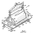
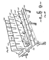
- Figure 1 illustrates a typical "master model" which would be utilized in presently practiced methods of aircraft manufacture.
- the master model 100 of this figure duplicates a major section of the fuselage of a typical high performance aircraft.
- the master model 100 includes many components, all of which are necessary to its construction and stability. These components allow it to serve as the "master" reference for individual components of the aircraft. Other molds such as master female molds are also made with the master model 100.
- the master model 100 is constructed with a base 104 which is supported on legs collectively identified by the numeral 106.
- the base 104 has to be formed as a structure which will support and hold the remainder of the master model 100 as stable and permanently fixed as possible over the life time of the master tool.
- the base 104 includes supporting I beams 108 attached to a steel base plate 110.
- the steel base plate 110 is of a thickness of one inch or greater. As is evident, just the base 104 itself constitutes a heavy massive structure.
- Permanently attached to the base 104 are a plurality of "candlesticks" collectively identified by the numeral 112 which are used to support optical targets such as cup mounts or targets 114.
- the cup mounts 114 are used as target points to "sight" with a hand operated optical device to level the base 104 and to serve as reference points on the master model 100.
- the legs 106 are adjustable for initially leveling the base 104 during construction of the master model 100.
- a reference plate 116 which has a plurality of holes collectively identified by the numeral 118 positioned at precise locations in the reference plate 116. These are utilized to correlate the master model 100 with other structures such as adjoining master tools (not separately shown or identified) or the above mentioned female masters made from the master model 100.
- Pillars collectively identified by the numeral 120 are fixed to the base 104 at both ends of the master model 100.
- a detachable beam 122 which can be connected to the pillars 120 supports a further reference plate 123.
- a ring 124 is located on the beam 122. The ring 124 serves as an appropriate attachment point for a derrick or crane to move the beam and reference plate 123 from the remainder of the master model 100 when it is necessary to do so to have direct access to the moldline surface 102.
- the master model 100 further has two end plates collectively identified by the numeral 126.
- the end plates 126 are fixedly attached to the base plate 110 with channels 128.
- the base plate 110 As is the base plate 110, the end plates 126 are also formed of heavy plate.
- the end plates abut against the pillars 120 to give stability against lateral movement along the longitudinal axis of the master model 100. Since all of the components of the master model 100 described so far are made of metal, they are subject to thermal instability.
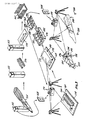
- the moldline is formed using a plurality of "profile boards" which represent sections through the moldline surface.
- Figure 2-b shows a drawing 130 on a drafting board 131 of one such profile board 132.
- the drawing 130 would be prepared by taking a section cut off of a master assembly or sub-assembly drawing of the aircraft under construction. After the drawing 130 for the individual profile board 132 is prepared, it is passed on to an NC programmer.
- the NC programmer inputs the data of the profile board 132 specified by the drawing 130 to an APT-AC processor. While certain software has been developed to assist the NC programmer the NC programmer must still determine all of the parameters for the tooling operation. This is a time consuming task. In any event, a postprocessor generates a mylar tape 134, shown in Figures 2-c, which is fed to an NC machine tool to direct the cutter path of the machine tool.
- Shown in Figure 2-a are three individual profile boards 136, 138 and 140 which have been cut on an NC machine tool. They each contain one profile edge, edges 142, 144 and 146 respectively. These profile edges have been cut to a specified tolerance on the NC machine tool to match, as accurately as possible, the profile specified for the "profile board" (as for instance, profile board 132) on the respective drawings which defines the respective profile board. Other than the profile edges 142, 144 and 146, the remainder of the profile boards 136, 138 and 140 are not cut to an exacting tolerance but only to a general tolerance.
- profile board 136 is exactly positioned on the base plate 110 independently locating the profile surface 142 in the X axis, the Y axis and the Z axis. It is then fixed in place on the base plate 110 with angle brackets collectively identified by the numeral 148. Note that the profile board 136 (as well as all other profile boards) must include sight holes, collectively identified by the numeral 150, in order to optically align between the cup mounts 114 on the respective ends of the master model 100.
- profile board 136 Once the profile board 136 is positioned, its position must be independently verified by an audit by inspection personnel. This is necessary because of the criticality of the master model 100 to the finished aircraft throughout the life time of the production of the aircraft or replacement parts for that aircraft. When all are satisfied that profile board 136 is positioned as accurately as possible in all of the X, Y and Z axes, the next profile board 138 can be placed.
- profile board 138 must be positioned individually so that its profile surface is correctly located in all of the X, Y and Z axes, and to insure that it is correctly located with respect to the profile board 136 (or boards) already in position. Profile board 138 is then fixedly attached to the base plate 110 with angle brackets 148, and its position verified by an independent audit by inspection personnel. This is repeated for the profile board 140 and all remaining profile boards. As is evident, this is a time consuming and, therefore, expensive process. Long lead times are necessary to construct these master tools such as master tool 100.
- plaster is "faired-in” between the profile boards by using the profile boards as a quide for a fairing tool pulled across the profile edges of the profile boards filling the space between the profile boards with plaster. This forms the moldline surface 102 of the master model 100.
- the moldline surface 102 master model 100 is then once again hand inspected using splines and feeler gauges. This inspection, however, is not an inspection back to engineering specification. It is only to insure that there are not high or low areas on the moldline surface 102 of the master model 100. If the master model is satisfactory, its surface is marked with identifying locations or holes which will be used when other tools are made from the master model or are checked against the master model.
- the master models are very heavy and generally cannot be oriented in any orientation except the orientation they are constructed in. Further anything which must be done in conjunction with them must be done at their storage site.
- the present invention dispenses with the necessity of the hard master tool concept. In its stead, it utilizes a "data model" of a structure which resides in computer memory or computer storage.
- This data model provides an engineering definition of the structure as well as additional information which is added to the data model. Since the data model resides in computer memory, for any and all operations in designing, manufacturing or assembly associated with the structure, access is always made back to the computer memory definition for information.
- data model is primarily utilized in this specification.
- "computer memory master design definition” "engineering electronic model”, “data base graphics model”, “assembly data model”, “3-D graphics model” or even “soft master” might be considered equivalent terminology for the "data model”.
- computer memory or “computer storage” is defined to be that of the typical definition utilized in computer science.
- memory or “storage” or “store” are considered synonyms.
- “Memory” or “storage” can be main or active memory in the usual computer science sense, or secondary memory also in the usual computer science sense. Except during active interfacing of the memory definition (the data model) of the structure to be built, for most purposes the memory definition (the data model) of the structure will exist in the normal secondary memory, i.e. magnetic drums, disks, tapes or optical memories or chip memories like ROM's, PROM'S, virtual RAM memories, etc.
- access back to the data model in computer memory can be made for all types of aircraft manufacturing procedures such as: the production of bonding tools, which are used to form and cure composite parts; for the production of assembly jigs for orienting component parts of the structure to one another; for the production of machined tools; for material ordering and processing; for the auditing or inspection of component tools and parts; for the assembly of component tool parts; for the assembly of the component parts into the aircraft structure; and other operations and procedures as will become evident from this specification.
- aircraft manufacturing procedures such as: the production of bonding tools, which are used to form and cure composite parts; for the production of assembly jigs for orienting component parts of the structure to one another; for the production of machined tools; for material ordering and processing; for the auditing or inspection of component tools and parts; for the assembly of component tool parts; for the assembly of the component parts into the aircraft structure; and other operations and procedures as will become evident from this specification.
- the data model can also include further information associated with the structure which is added to the data model throughout the manufacturing steps of the structure. With each step utilized in the entire manufacturing process of the structure, the same dynamic computer memory definition of the structure is utilized. This computer memory definition is not subject to environmental conditions and it can be shared or duplicated so that it is available to many users at one time
- a data model of a structure of this invention inherently includes an exact engineering description of the structure since, among other things, it is the engineering definition of the structure. This is opposed to the master tool concept which was fabricated as best as possible to "represent” the engineering definition of the structure. And contrary to the hard master tool concept, a change can be made to the data model definition of the structure and be reflected through the totality of the manufacturing process of the structure.
- the data model replaces the various master models and other master tools, and in their stead it uses a single mastering source for all of the manufacturing processes and assemblies. Further, since component parts of the data model can be utilized by many users at the same time, parallel manufacturing and assembly can be achieved. Thus, as opposed to the old hard master concepts, an assembly jig can be constructed concurrently with a bonding tool since neither is dependent on the other for its construction and assembly. This is diametrically opposed to the old hard master concept wherein a gauging master was necessary before the assembly jig could be completed.
- data representing actual physical components parts, tools or jigs, as formed can also be stored as a component part of the data model with the engineering definition. Because of this, all deviations are always known for archival and quality control purposes. Additionally, if desired, the actual engineering definition could be changed to reflect changes or upgrades in component parts, and these changes would be propagated to other tools, jigs, assembly instructions, and the like. Also parts and tooling can be constructed and assembly effect in simulation to uncover any construction problems which may not be inherent during design.
- the data model of the structure is initiated in an appropriate computer system by first entering the engineering definition of the structure. Virtual tools necessary to fabricate the component parts of the structure are then also defined in the data model. These data model definitions can then be downloaded to emulating means for the production of the component tool parts. Further, these definitions are downloaded to domain interface means for comparing the tools, assembly jigs and the like, and actual physical component parts, to the data model definition of the structure or the data model definition of associated tooling structures which are also created in the data model. The definition downloaded to the domain interface means can also be utilized for assembly of the component parts into the structure or parts of the structure.
- the tools for forming bonding tools and bonding tools represent both direct image copies of the moldline of an aircraft and complementary image copies.
- a further embodiment will illustrate the construction of an assembly jig utilizing the principles and concepts of the invention.
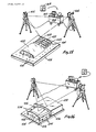
- Figure 3 schematically shows the overall construction of an aircraft from conception to finish and highlights the above described illustrative embodiments. Certain of the steps and structures pictorially presented in Figure 3 will be expounded upon in greater detail and referenced in other figures of the drawings. Where indicative of continuity between different figures, "like" numerals will be utilized to identify like or “similar” parts. When certain structures or processes are described in greater detail than as described in Figure 3, further numerals will be utilized to identify parts similar to those shown in Figures 3 or other figures.
- a computer system 152 is utilized to create an engineering definition or master design definition of an aircraft 154 in a data base in the computer system 152.
- the aircraft 154 is only a virtual aircraft since it only exists as the engineering definition in a data base in the computer system 154. This forms the initial entry into the data model for the aircraft structure.
- the computer system 152 is chosen as a computer system running a 3-dimensional graphics software program and, as such, the data model or master design definition is a 3-dimensional (for brevity hereinafter referred to as 3-D) graphics design definition.
- 3-D 3-dimensional
- Such a definition will include coordinate points precisely locating the data model or master design definition in a 3-D coordinate system.
- a 3-D graphics software program will utilize appropriate data structures for defining particular points in the data base of the graphics program. By utilizing algorithms in the graphics program, other points in the structure can be defined and generated by the graphics program.
- the graphics program will utilize appropriate vector and matrix routines whereby a structure can be rotated or otherwise moved in computer memory and can be dimensioned whereby the coordinates for any one point are known with respect to other points.
- the data model will be created in the computer system 152 and stored in an appropriate file or files in a data base in computer memory. Further, a data set or data sets of this data model, or portion thereof, from the data base file or files can be downloaded from memory through appropriate output devices associated with the computer system either as memory words (that is the particular word size in bytes for the computer system) on appropriate data buses or input/output (I/O) data ports, as appropriate memory images (magnetic or optical data read/write data transfer), or by creation of hard copies of the same (printer output, etc.). Additionally, many users can be networked into the data model for parallel interaction with the data model.
- an appropriate component section of the aircraft structure is selected and a virtual tool 156 for constructing the selected section is defined in the data model within the computer system 152 (or other equivalent computer system).
- a virtual component part 158 of the virtual tool 156 is further defined in the data model.
- the virtual part 158 and the remainder of the parts of the tool 156 are constructed by an tool making means (not separately shown or numbered in Figure 3) to form a corresponding actual tangible part 160 and other corresponding parts not separately shown or numbered.
- the part 160, along with the remaining corresponding parts, are collected in a kit rack 162 for assembly. When all of the component parts are collected in the kit rack 162 for assembly, they are assembled together, as for instance, on a grid surface 164 into bonding tool formation precursor tool 166.
- a copy from the data model of the data set containing the definition of the virtual tool 156 is downloaded from the computer system 152 for transfer, as is represented by floppy disk 168.
- the data set for the virtual tool 156 is transferred to a computer aided theodolite system 170, as for example via the floppy disk 168.
- the computer aided theodolite system 170 and the floppy disk 168 serve as one example of a domain interface means for comparing the tangible tool 166 to its data model definition defined by the virtual tool 156 in the data model. As will be described in greater detail below, this is done utilizing 3-D coordinating points on the tangible tool 166 or the surface 164, or both, and comparing them to the coordinate points in the 3-D coordinate system of the data model in the data base created by the 3-D graphics software running on the computer system 152.
- the surface of the bonding tool formation precursor tool 166 is faired-in with plaster to complete the bonding tool formation or transfer tool 172.
- This section of an aircraft is constructed via a tangible tool (the tool 172) which corresponds to a virtual tool, virtual tool 156, in the data model.
- the virtual tool in turn corresponds exactly to the engineering specification of the aircraft in the data mode.
- the moldline image 174 on the bonding tool formation tool 172 can be compared to its virtual counterpart, a virtual surface on the virtual aircraft 154 in the data model by interfacing between the data model and the surface 174 with the domain interface means characterized by the computer aided theodolite 170 and the floppy disk 168.
- the bonding tool formation precursor tool 166 By building the bonding tool formation precursor tool 166 on a surface which has known spatial identifiers 178 on it, i.e. a grid pattern standard, and coordinating, via the computer aided theodolite system 170, these spatial identifiers 178 with the data model, the precise location of coordinating points on the bonding tool formation tool 172 and these spatial identifiers 178 can be established and can be referenced to the data model.
- a bonding tool 176 can now be molded on the bonding tool formation tool 172. However, if the bonding tool 176 is molded not only from the bonding tool formation tool 172 but is also partially formed against the surface 164, and if prior to molding the bonding tool 176 on of the bonding tool formation tool 172 and the surface 164, precision target pins 180 are inserted in the spatial identifiers 178 on the surface 164, then when the bonding tool 176 is formed on both the bonding tool formation tool 172 and the surface 164, the target pins with assigned values will transfer precise location holes 182 to the bonding tool. These location holes 182 can now serve to reference the bonding tool 176 to the data model.
- the spatial identifiers were coordinated to the data model and the 3-D coordinate system in which the virtual aircraft 154 is defined, when they transfer via the target pins 180 to the bonding tool 176, they become target holes 182 with known values. That is, the target holes 182 are precisely known in 3-D space with respect to the master design definition of the virtual aircraft 154. Since the target holes 182 are known in 3-D space, the computer aided theodolite system 170 can be used to locate any further points which are desired on the surface of the bonding tool 176.
- component pieces of the part 184 can be precisely positioned on a composite skin 190 via the target holes 182 or other identifiers (discussed below) on the bonding tool 176.
- a virtual assembly tool (not separately shown or numbered on Figure 3) could also be defined. Instead of it containing a surface (a virtual surface corresponding to the skin panel 190), it would include locator points abutting against or cutting into that surface (points complimentary to or intersecting that virtual surface). In any event, it would be defined, and from its definition component parts would be machined and built in a manner equivalent to the bonding tool formation precursor tool 166 to form an assembly jig 192.
- This assembly jig 192 is used in conjunction with other assembly components, collectively identified by the numeral 194 in Figure 3, to assemble component parts, including the component part 184 into an aircraft structure 198.
- the positioning of the component part 184 on the assembly jig is done utilizing the computer aided theodolite system 170 and a data model data set on the floppy disk 168.
- known locators 196 are specified and located on the assembly jig 192 as known positions in 3-D space (in a manner as described for the spatial identifiers 178 or target rod 180) and the computer aided theodolite system 170 is used to align target points or coordinating points on the component part 184 with corresponding locators 196 or coordinating points on the assembly jig 192.
- the totality of the aircraft 198 is assembled with the aid of a copy of the data model containing the definition of the virtual aircraft 154 which has been downloaded as a data set to the floppy disk 168 and inputted into the computer aided theodolite system 170.
- known spatial grid points collectively identified by the numeral 200, (equivalent to the spatial identifiers 178) can be located within the assembly cell as for instance in the assembly bay floor and entered into the 3-D coordinate system of the computer aided theodolite system 170.
- the aircraft 198 is assembled by utilizing virtual images of the target points 200 in the computer memory as coordinating points between the virtual image (the virtual aircraft 154 in the data model) and actual aircraft 198. This is done by coordinating the virtual images of the target points 200 to the tangible target points 200 via the computer aided theodolite system 170.
- the virtual images of the target points 200 are downloaded as a data set from the data model to the floppy disk 168. The floppy disk then serves as the transfer medium for input of these virtual coordinating points to the theodolite system 170.
- the virtual aircraft 154 is constructed utilizing an interactive 3-D graphics CAD program. Normally a design engineering team would construct the virtual aircraft 154 using a CAD program or programs and interface devices such as light pens, function key boxes, graphics or digitizing tables, tablets or boards, or a computer mouse. Of course all of these would also be utilized in conjunction with keyboard entered commands. Insofar as CAD programs of this type are commercially available and the above interface devices are also, a detailed description of the operation of a particular program or device is not deemed necessary to the understanding of this invention.
- a 3-D CAD program or programs such as CATIA (IBM Corporation) or NCAD and NCAL (Northrop Computer Aided Design and Northrop Computer Aided Lofting, Northrop Corporation, Hawthorne, CA) would be suitable to define the master engineering definition of the aircraft 154 in 3-D graphics in the data model.
- This master engineering definition is created and stored in a file or files in a data base.
- other software can be used to assist in the design chores.
- NORLOFT Northrop Corporation
- a known CADAM 2-D graphics software available from the Lockheed Aircraft Corporation
- the master engineering definition, or other entries in the data model would be done on a suitable computer system such as an IBM 3090-200 mainframe, an IBM 3081 mainframe, or an IBM 4381 mainframe using an appropriate operating system such as the IBM MVS-XA (Multiuser Virtual Storage-Extended Architecture).
- Engineering data or other data input to the data model would typically be done at an appropriate work station such as an IBM 3278 terminal or an Adage workstation equipped with appropriate interface devices, as described above.
- the workstation or workstations would be appropriately interfaced with the mainframe using appropriate software such as the IBM TSO (Timesharing Option) software which allows both downloading and uploading between the respective computer devices.
- IBM TSO Timesharing Option
- This provides the workstation with a microcomputer working environment while still providing access to the mainframe library allowing the generation and use of a "single source" information data base for the data model.
- CAD systems such as the ME Series 30 CAD (Hewlett-Packard) are designed to run on specific computer hardware such as Hewlett-Packard mini-computers while CAD software packages such as AutoCAD (Autodesk, Inc.) are available for micro-computers such as an IBM AT computer running a DOS operating system on an Intel 80286 microprocessor and 80287 math coprocessor.
- ME Series 30 CAD Hewlett-Packard
- AutoCAD Autodesk, Inc.
- the master engineering definition is created in 3-D graphics such that it includes appropriate coordination of the engineering design in a 3-D coordinate system.
- This design definition could be as a wire model or could utilize solid surfaces to form a hidden surface type model. Or it could include both of these as would be included in the CAD design software package.
- the data model is initialized by inputting the master engineering definition of the aircraft in the 3-D graphics program as a data set or data sets (and stored as a file or collection of related files or other like association) in a data base (or other like software) in the computer system.
- a data base or other like software
- copies of the totality of the data model or portions thereof as data sub sets can be downloaded (for instance, as individual files) from the mainframe library in an appropriate manner using, for instance, the above mentioned TSO software to download from the above mentioned computer system to further computer systems or data interfacing devices.
- the data model can be interfaced either through a human operator or through other software.
- the interaction with the human operator with the assistance of certain described software
- the interaction with the human operator will be described and then supplemented below where appropriate with respect to software emulating the steps performed by the operator.
- a design engineer, programmer, or other operator using the data model or a portion of the data model and interacting with the computer system downloads the data model or a portion of it (normally by downloading files containing this data) and interacts with the data model or portion thereof with the use of the above noted operator interface means, i.e. light pens etc., at work stations 202-a to 202-c.
- the loft lines of the virtual skin panel 206 in workstation screen 208-a suggest suitable profile cuts which can be used to define the skeleton for a virtual tool such as the virtual tool 156 of Figure 3
- the individual loft lines each form a locus in a virtual surface 210 which includes the virtual skin panel 206. Using some of these loci (as for instance the ones traversing from the upper left to the lower right in workstation screen 208-b of Figure 5), or other lines, curves etc.
- the operator might create using the above noted operator interface means, the operator extends these loci in the surface 210 beyond the trim line of the virtual panel 206 and then away from the panel 206 in the direction of the interior of the virtual aircraft 154 and truncates them in a plane such that they form a plurality of virtual planes 212 which intersect or cut into the virtual surface 210.
- the operator (or equivalent software such as the TCAD software) has now created the virtual tool 156.
- the graphics definition of the virtual tool is stored in computer memory as a part of the data model of the aircraft. Since the computer memory does not have any prejudice as to just what is or is not part of an aircraft, the tool design can become part of the data forming the data model of the aircraft 154.
- the portion of the data base containing the definition of the virtual tool 156 can be accessed and utilized for the manufacture of an actual tangible tool corresponding to the virtual tool 154.
- a data sub set (for instance as a file or files) of the data model data base can be created which would contain just the data defining the virtual tool 154.
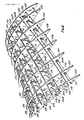
- Figure 6 shows a tangible tool 218 equivalent to the bonding tool formation precursor tool 166 of Figure 3. While the tangible tool 218 and other tangible tools of Figures 9, 15 and 16 might at first appear to be very similar to the old "master tools", they are not.
- the tangible tools of Figures 6, 7, 8 and 9 are not masters, they are working tools whose master exists in the data model in a data base in computer memory. They do not form the definition of a component; they are an expression of an already existing definition - the data model engineering definitions. As will be evident below, they can be reproduced if desired - they are not compromises of the engineering data as are the "master tools". They are precise expressions of the engineering definition of these tools. They can include explicit 3-D coordinate system locating points incorporated directly into their structure. They can include inherent surfaces of locator means which precisely position or locate each component piece with its respective neighbors as well as other attributes, as will be evident from this specification.
- the tool 218 is composed of a plurality of profile boards 220, 222, 224, 226, 228, 230, 232 and 234. These "interact" with connector boards 236, 238, 240 and 242.
- Each of the profile boards 220, 222, 224, 226, 228, 230, 232 and 234 includes downwardly facing slots collectively identified by the numeral 244; one for each of the connector boards.
- Each of the connector boards 236, 238, 240 and 242 includes upwardly facing slots collectively identified by the numeral 246; one for each of the profile boards.
- Most of the slots 244 and 246 in Figure 6 have been covered and sealed with an aircraft sealant. However, each is as is shown in Figures 7 and 8.
- the above referenced slots 244 and 246 are essentially "lap joints", albeit very special ones that, as will been seen, include an automatic rigging or positioning faculty.
- the depth of the slots in either the profile boards or the connector boards is of a depth allowing the profile boards to fit over and interlock with the connector boards with the bottom of the profile boards (as more fully described below) in contact and fitting against a supporting planar surface.
- connector board 2308 In Figure 7, to facilitate illustration, only one connector board, connector board 238, is illustrated. Further, only two profile boards, profile boards 220 and 232, are shown in Figure 7; and in Figure 8 only fragments of profile board 232 and connector board 238 are illustrated. As is seen in Figures 7 and 8, all of the slots in the connector board 238 face or open upwardly. Further, all of the slots in the profile boards 232 and 220 face or open downwardly. Because of this, the profile boards can be slid downwardly onto the connector boards.
- a profile edge, collectively identified by numeral 248, on each of the respective profile boards 230 to 234, is precisely machined to exact specifications on an NC machining tool, as is hereinafter described.
- the bottom surface or portion thereof such as feet, collectively identified by the numeral 250 on all of the respective profile boards 220 to 234) is also machined to exact specifications. Because of this, if the feet 250 of each of the respective profile boards 220 to 234 are positioned in the same Z plane, the profile edges 248 are, therefore, also positioned with respect to that Z plane.
- Each of the slots 244 on the respective profile boards 220 to 234 is machined to include a locator edge 252 and a non-locator edge 254.
- the locator edges 252 are machined in the profile boards to exact tolerances and orientations with respect to the profile edges 248 and the feet 250.
- the non-locator edge 254 is cut such that the slots 244 are wide enough to accept the thickness of the connector boards plus a non critical increment.
- Each of the slots 246 includes a locator edge 256 machined to exact specifications, and a non-locator edge 258 which is not critical but is spaced from the locator edge 256 an amount sufficient to allow the profile boards to fit into the slots 246 with a small amount of excess space.
- a plurality of small wedges 260-A and 260-B are used to secure and also concurrently precisely locate the respective profile boards 220 to 234, and the respective connector boards 236 to 242, to one another to form a precision three dimensional structure.
- the wedge 260-A is pushed between the non-locator edge 258 of the slot 246 on the connector board 238 and near face 262 of the profile board 232 to push far face 264 of profile board 232 tightly and accurately against the locator edge 256 of the slot 246 in the connector board 238
- the wedge 260-B is pushed between the non-locator edge 254 on the profile board 232 and near face 266 of connector board 238 to push far face 268 of connector board 238 tightly and accurately against the locator edge 252 of the profile board 232.
- This is repeated for each of the intersections of a respective profile board 220 to 234 with one of the respective connector boards 236 to 242.
- the profile boards and the connector boards are so assembled or automatically rigged into the tangible tool 218, it resembles an egg crate type structure.
- This assembled tangible tool 218 is an extremely precisely oriented and dimensioned structure.
- brackets are used to fixedly hold the end profile boards 220 and 234 to several of the connector boards. As for instance, connector boards 238 and 240.
- Brackets 270 would be attached to the respective profile boards 220 or 234 and the connector boards 238 and 240 after their position to one another was established by locating the profile boards 220 and 234 against the locator edges 256 on the connector boards 238 and 240, and the connector boards 238 and 240 against the locator edges 252 on the profile boards 220 and 234.
- the locator edges 252 in the slots 244 in the profile boards would all be oriented the same way in space. As for instance, they would all be the far edges as viewed in Figures 6, 7 and 8.
- the locator edges 256 in the slots 246 in the connector boards would all be oriented the same way in space. For example, they would all be the far edge as viewed in Figures 6, 7 and 8, except for the locator edges 256 on the connector boards which interact with the end profile boards 234.
- the locator edges 256 for the profile board 234 would be on the near edge of the slots 246 in the respective connector boards 236 to 242.
- brackets 270 and the need to have one "odd” orientation of the locator edges 256 on the connector boards 234 to 242 for the end profile board 234, can be eliminated by simply extending at least one of the connector boards 236 to 242, respectively, slightly longer than the distance between the end profile boards 220 and 234 such that a "full" slot, as opposed to just one locator edge 256 (a half of a slot), is included on one or more of the connector boards 236 to 242, respectively. This full slot is then used to fix the end profile boards 220 and 234 to the connector boards.
- Each of the respective profile boards 220 to 234 and the respective connector boards 236 to 242 includes a large vent hole, collectively identified by the numeral 272, to vent the structure when it is faired-in with plaster, as described below.
- the profile boards 220 to 234, respectively each include a plurality of plaster support rod holes, collectively identified by the numeral 274. Plaster support rods, collectively identified by the number 276, are passed through the holes 274 and attached to the respective profile boards 220 and 234 with "Tinnerman nuts", collectively identified by numeral 278. The attachment of the plaster support rods 276 to the profile boards is not critical to the orientation or the precision of the tangible tool 218
- wire mesh 280 is laid on top of the plaster support rods 276 and first a rough plaster 282 is laid over the mesh 280 and then a finish plaster 284 is faired-in using a fairing tool against the profile edges 248 on the respective profile boards.
- the plaster support rods 276, the mesh 280, and the two plaster plies are standard as per the plaster fairing of the old "master tool" concept.
- a transfer model 286, similar to the tool 172 of Figure 3, has been constructed.
- This transfer model 286 and its precursor tool 218 have been constructed on a grid table.
- the support surface has not been incorporated as a part of the finished tool nor is it necessary to do this (however, as is shown in a further embodiment below, optionally a surface could be included but is can be formed as a light weight aluminum surface which does not need I beams, legs etc).
- planar surface 288 The flat horizontal surface used during assembly of the tool 218 of Figure 6 and its faired plastered counterpart tool 286 is the planar surface 288. This is shown in Figure 7 and in part in Figure 6. It need not be horizontally orientated in space except this is very convenient for the assembly personnel.
- the planar surface 288 is used during construction of the tools 218 and 286 but it does not physically become a permanent part of them.
- the planar surface 288 is a flat plane which has been "Blanchard" ground such that it is very flat and contains a precision matrix of precisely sized holes, collectively identified by the numeral 290.
- the holes 290 are located in precise parallel lines: one set in the X axis and one set in the Y axis, to form a precision grid of squares each defined by four holes. Because of this, knowing the location of any two holes on the surface 288 in three dimensional space establishes a line on the surface 288 in three dimensional space and, knowing the location of any three holes on the surface 288 in three dimensional space, establishes the location of the plane of the surface 288 in three dimensional space. The holes, thus, serve as target means for defining a position in three dimensional space.
- coordinating points are established on at least one of the profile boards. These coordinating points could be a point where three edges meet. As for instance, at either of the corners of profile board 220 in the near foreground of Figure 6. Normally, they are chosen as explicit points which are placed at convenient locations on one or more of the profile boards.
- Coordinating holes are shown machined into the profile board 220 of Figures 6 and 9, and the profile board 232 of Figures 6 and 8. These holes are sized to accept small precise target pins 295 shown in detail in Figure 19 which fit into them forming coordinating points with assigned X, Y, and z values on the profile boards. Similar target pins, albeit larger ones, target pins 294 (also shown in detail in Figure 18), are used in conjunction with the holes 290 in the surface 288.
- a coordinating line 293 is located normal to the profile edge 248 of selected profile boards. This forms coordinating target values directly on the profile edge which becomes part of the faired plaster surface. Alternately, the coordinating points could be formed as crossed scribe lines. This would eliminate the need for target pins 295.
- a computer aided theodolite system such as the system 170 noted in the discussion of Figure 3, is used to establish a three dimensional coordinate system by establishing in three dimensional space the spatial positions of the holes 290 in the surface 288 using the target pins 294.
- the theodolite system 170 would establish the three dimensional coordinate system using the spatial position of a profile board (or connector board), such as profile board 220, via the coordinating holes 292 and target pins 295 or lines 293 or other precisely located points on the board.
- the target pins 294 are formed as stepped cylinders having centered cross hairs scribed on their top surface.
- Related locator pins 297 are formed with a hemi-cylindrical upper section however their bottom section is identical to the pins 294 allowing them to also fit into surface grid holes such as holes 290 on surface 288.
- the locator pins 297 seen in Figures 6, 7, 8 and 19 are very useful during assembly of tools such as the tools 218 and 286 since the flat planar near or far faces 262 and 264 of the profile boards fit precisely against them and form a mating edge.
- the pins 297 can include a scribe line which is normal to that mating edge. Thus the scribe line serves as a first "cross hair" and the mating edge of a board serves as the other "cross hair". Because of this, the pins 297 can also serve as target pins.
- the edge of a board positioned against the locator pins 297 is directly centered over the center of a hole such as hole 290 in surface 288 and is held in this position.
- the edge of the board is fixed in the X (or Y) plane with respect to the surface.
- the surface 288 was established in three dimensional space using the pins 294 and a computer aided theodolite system such as system 170 and then a profile board, such as board 220 was established on the surface 288, the relationship of the surface 288 with respect to the board 288 is known. Now when the remainder of the tool 218 is assembled on the surface 288, the tool 218 now has been assembled in a known position in a three dimensional space coordinate system.
- the locator edges 252 and 256 establish perpendicular X and Y planes, and the surface 288 adds the orthogonal Z plane.
- tool 218 After the tool 218 is established in three dimensional space, it is faired-in with plaster to form the tool 286. Since the tool 286 inherits the characteristics of the tool 218, tool 286 is also established with respect to three dimensional space.
- the tool 286 is now used in conjunction with the surface 288 as a mold for a bonding tool.
- the pins 294 are positioned in the surface 288, and the bonding tool cast so as to include part of the surface 288 which contains these pins 294.
- the target pins 294 transfer as holes 296 in the bonding tool 298 of Figure 10.
- the bonding tool inherits this orientation in three dimensional space allowing the bonding tool 298 to be oriented with respect to the same three dimensional coordinate system in three dimensional space and to carry its own target coordinating points, the holes 296 created by the spatially known pins 294.
- a number of connector boards 236 to 242 were utilized. Instead of using a plurality of connector boards, a single connector board could have been used if it was made sufficiently wide to provide for maintaining the respective profile boards 220 to 234 parallel to one another. For machining, economics, structural and material considerations, it is preferable to utilize a number of connector boards made from thin flat stock versus one made from wide stock.
- a base as a part of a tool transfer model, as for instance when the shape of the tool is very narrow.
- the number of connector boards which can be used is limited simply because of space consideration.
- a further embodiment of the invention shows the use of a limited number of thin flat connector boards (that is components machined from thin plate sheet versus heavy bar stock) plus a thin base board. This is shown in Figure 11.
- FIG 11 two bonding tool formation tools, completed tool 300 and incomplete tool 302, are seen. Both of the tools 300 and 302 are long and narrow. They are, in fact, tools for making a right side part and a left side part, i.e. mirror image configurations. Because they are long and narrow, as is seen with tool 302, only one central (or internal) connector board 304 is used.
- the profile boards collectively identified by the numeral 306 (only those of tool 300 being shown), extend or would extend when the tool 302 is finished, out beyond the back connector boards 308 and 310 of the tools 300 and 302, respectively, and also beyond the front connector board 312 of tool 302, and the unseen front connector board (not separately shown or numbered) for the tool 300.
- slots can be placed in the profile boards 306 for the back connector board 308 of tool 300; the back connector board 310 for the tool 302; the front connector board 312 for the tool 302; and the unseen front board for the tool 300. This adds to both the stability and to the precision of the tools 300 and 302 and other tools.
- the base 314 of tool 302 as well as the base 316 of tool 300 are initially positioned on the table surface 318.
- the table surface 318 is a duplicate of surfaces 164 and 288 discussed above. All of these surfaces 164, 288, or 318 could, in fact, be the exact same surface which is being used at a different time for a different tool.
- the surface 318 also includes a hole grid 320 in which locator pins 297 are being used to locate the bases 314 and 316 with respect to the surface 318. In locating the bases 314 or 316 to the surface 318 we are concurrently locating the tolls 302 and 300 constructed thereon relative to the surface 318.
- Angle brackets 322 are used to first initially support the connector boards 304, 310, and 312 on the base 316.
- the profile boards are positioned on the connector boards 310, 304, and 312, and wedged together, as was described for the tool 218.
- the tool 302 is then fixed to the base 314 by securing the angle brackets 322 to the base 314.
- the brackets 322, after being secured to the base 314, would serve this function. It is preferable however, to include the wedges.
- both of the tools 300 and 302 are being assembled simultaneously on a single surface 318. Both of the tools 300 and 302 can be moved from the table surface 318 when the assembly of these tools is complete. The table surface 318 is then free for the assembly of further tools.
- the tool 286 can also be removed from the surface 288 after the bonding tool 298 is pulled from it.
- a representational machine tool 324 is seen forming a representational Z plane surface 326.
- This corresponds to the surfaces 164 and/or 288 and/or 318 or other standard surfaces which might be established.
- a Z plane will be needed for each tool, it can be the same Z plane which is reused over and over again and need not be remanufactured, leveled, stored, etc., again and again for each different tool as is necessary with the old "master tool" way of manufacturing.
- FIG. 5 Just below the representational machine tool 324 in Figure 5 is a further representational machine tool 328 which is forming a plurality of parts, collectively identified by the numeral 330. These correspond to the individual unique parts of an individual unique tool such as those of tool 218. As can be seen in Figure 5 by the representational machine tools 324 and 328, and the parts they form, tools for use in constructing tangible surfaces which mimic the surface 210 in the workstation screen 208-b, can be constructed utilizing a standard component, surface 326, for one plane, the Z plane; and unique component parts 330, for definition in the other two planes, the X and Y planes.
- the standard component, surface 326 always gives at least one way of accessing back to the master engineering definition of the aircraft structure in the data model.
- a workstation operator or appropriate software can normalize each of the members of a family of virtual tools which are being formed at the workstation screen 208-b (or in memory if software is being utilized) to the standard Z plane component by simply defining a Z plane shown by the representational arrows 332-332 in the lower left hand corner of Figure 5 associated with the virtual planes 212. This is easily done by an operator utilizing his light pen or other input device.
- This Z plane 332-332 now creates a tool origin or configuration noted by the coordinates 334 which can (but does not necessary have to) differ from the aircraft origin or coordinates 336. If the tool coordinates 334 do differ from the aircraft coordinates 336, they are, however, both known to the graphics software and, thus, the data model and can always be referenced back to one another.
- a tangible tool such as tool 172 in the upper right hand corner of Figure 5, which is located on surface 164, is being measured using tool coordinates by referencing coordinating points on either the tool 172 or the surface 164, since the tool coordinates in the data model (workstation screen 208-c) are known with respect to the aircraft coordinates (by matrix rotation or the like in the CAD software), the tangible tool is, therefore, also known with respect to the aircraft coordinates.
- an operator or appropriate software such as the above referenced TCAD computer aided tool design program, selects the portion (normally a file or files) of the data set from the data model data base which defines the virtual tool 156 and brings this data set up into working memory.
- the data containing the definition of one of the virtual profile boards 214 is selected.
- the selected boards 214 is individually identified as component 338.
- the component 338 is a virtual profile board and ultimately a tangible counterpart will be formed which will be one of the profile boards of a transfer model tool, as for instance tool 286.
- TCAD Computer-Aided Manufacturing
- TCAM Computer aided Manufacturing, Northrop Corporation
- TCAM Tooling Computer-Aided Manufacturing, Northrop Corporation
- MAXCAM Multi-Axis Computer-Aided Manufacturing, Northrop Corporation
- MAXCAM is an interactive graphics numerical control programming system which utilizes an interactive graphics terminal to develop, simulate and submit a machine program to an APT processor.
- a MAXCAM standard tool library is maintained in a logical and hierarchical manner in a data base.
- IBM DB2 data base management tool IBM Corporation
- IBM Corporation IBM DB2 data base management tool that allows for ad hoc queries and rapid report utilizing tables of attributes pertinent to items like feed rates, speeds, etc.
- a data set from the data model data base containing the component 338 is loaded into working memory and onto the workstation screen 208-D in Figure 4-b.
- the profile edge 340 has already been defined. It was defined by the intersection of virtual planes 212 (corresponding to the virtual profile boards 214 of the virtual tool 156 of Figure 4-a) with the virtual surface 210 (see workstation screen 208-b of Figure 5).
- the virtual surface 210 in turn included the virtual part 206 from the virtual aircraft 154.
- the bottom edge 342 also has already been defined by cutting with a plane as per the Z plane 332-332 of Figure 5 described.
- the intersect lines 344, 346 and 348 do not - they define where one tangible component will interface with another. At this point in time the intersect lines 344, 346 and 348 do not yet have thickness corresponding to the thickness of these respectively tangible components. In view of this, they can be used to define the virtual counterparts of the locator edges 252 on corresponding tangible profile boards.
- the operator working with his or her light pen or other interface device, and having decided, for instance, that all of the locator edges will be on the left hand side of all slots in the profile boards, defines the slot 350 which contains the locator edge 344 by moving the light pen to trace this slot to the right of the intersect line 344. This defines the slot 350 and leaves the intersect line 344 as the locator edge in that slot. Since the intersect line 344 is precisely known in the coordinate system of the graphics software, the locator edge it now defines will also be precisely known.
- the virtual component 338 on the workstation screen 208-D of Figure 4 has been modified into a complete virtual profile board 360 shown in the workstation screen 208-E of Figure 12-a.
- the virtual profile board 360 is saved in the data base and becomes a component part of the data set forming the data model.
- Figures 12-a to 12-c show the formation of a tangible part from the memory definition of the same in a data base by using further improvements of this invention.
- the operator loads the data set (the file) containing the virtual profile board 360 onto the workstation screen 208-F of Figure 12-b.
- the operator also loads, as is shown on workstation screen 208-F, an interactive graphics numerical control programming system depicted as the indicia 362 on the screen 208-F.
- One such interactive graphics programming system is above referenced MAXCAM which interfaces with an operator utilizing menus which describe "tool macros".
- the above referenced TCAM software would be used to further limit the amount of operator interfacing.
- the workstation screen 208-F presents the operator with a choice of various tool macros.
- Each of these tool macros defines an automated machining operation.
- Some of the macros describe non-machining processes such as cooling on, cooling off, tool change, etc.
- Others describe machining operations such as face mill, drill, rough and finish pocket, rough and finish profile, regional mill, or flange top.
- Machine operator instructors can also be entered with appropriate details for the machinist, as can instructions for the formation of 2-D plan drawings for the machinist's use if necessary, depending on the ultimate machine which will be used to form the component part.
- the operator first selects planning macros which interface with the NC machine library of the system.
- the necessary planning information to be utilized by other macros such as part information including material type and condition, is entered; next, machine tool characteristics, such as number of axes and spindles, bed size, part orientation or maximum X, Y, and Z travel is also entered. Further fixture information like number of stages, tool design information, and clamp types and location are entered.
- stage design is entered.
- the operator can enter routines to develop multiple stage fixtures, fixture definition, tooling tabs, etc.
- cut programming begins by selecting the cut macros (drill, ream, etc.) for the geometry and, as these are entered, the cutter and its parameters (speed, feed, etc.) are defined.
- the geometry of the cut is picked and the macro is executed.
- the operator can then simulate the cutter movements through visual representation, as is shown on the workstation screen 208-F in Figure 12 showing the operator the "on the fly” cutter paths to produce the tangible component corresponding to the virtual profile board 360.
- an NC cutter tap 364 is now generated.
- the cutter information is directly downloaded via a data bus 366 to a digitally controlled machine tool (a computer numerical controlled tool) which resides in the software post processor file, or to an interface medium such as floppy disk 368 for indirect transfer to such a digitally controlled tool. Transfer to a digitally controlled tool can also be through a further computer system such as a micro or mini-computer
- the tape 364 or disk 368 or direct bus 366 computer control is then utilized to run an appropriate tool means such as NC machine tool 370 to cut a tangible profile board 372 from suitable feed stock 374.
- an appropriate tool means such as NC machine tool 370 to cut a tangible profile board 372 from suitable feed stock 374.
- the component formation information can be used to direct component part formation by other tools, such as numerically controlled laser cutters, numerically controlled assembly robots, computer numerically controlled machine tools, computer numerically controlled laser cutter and computer numerically controlled assembly robots.
- the tool 370 cut the outside profile, slots and locator edges, plaster rod holes, and vent holes of the tangible part 372, it also forms the coordinating target points (holes, cross scribe lines, etc.) directly on the tangible component part 372. This, then, places a direct reference on the component part 372 for location in a know precise position and orientation in 3-D space for referencing and locating the part 372 to other components, tools, parts, etc. residing in the data model for the aircraft structure.
- the operator can call up a further copy of the file of the virtual part 206 and/or the virtual surface 210 derived from the virtual surface 206 from the data model and load it on a workstation screen 208-G.
- the operator utilizes this virtual surface 210 to form a tool (as for instance, virtual tool 156) which included and, therefore, mimicked the surface 210 (an image copy of it).
- a complementary image tool can also be formed.
- the operator defines a virtual assembly jig 376 on the virtual surface 210.
- a tangible component is formed which corresponds to this virtual assembly jig 376, it will be complementary to the surface of the actual tangible part such that the surface of the actual tangible part can be positioned against the assembly jig and a required assembly operation performed on the actual tangible part in conjunction with the assembly jig.
- such assembly jigs would be used to locate parts during drilling, bonding, or joining and the like, where one part is prepared for assembly to an adjacent part or is fixed in position during actual assembly of these adjacent parts.
- target points can be added to the assembly jig such as the virtual target points, collectively identified by the numeral 378. Since these target points 378 will become part of the data set defining the virtual assembly jig 376 in the data model of the aircraft, when a tangible assembly jig corresponding to the virtual assembly jig 376 is formed, tangible target points will be known on the tangible assembly jig. These tangible target points will, therefore, be known a in precise relationship with the part which will correspond to the virtual surface 210, and they will also be known with respect to the total structure of an aircraft corresponding to the virtual aircraft 154
- a virtual gantry structure 380 i.e. an assembly structure rough structure, can also be designed at the workstation 208-G. This gantry positions and holds the virtual assembly jig 376 in space. Appropriate locators or coordinating points, collectively identified by the numeral 382, can also be included on the virtual gantry 380.
- locators or coordinating points collectively identified by the numeral 382
- tangible aircraft parts being assembled, drilled or the like in conjunctios with the tangible assembly jig corresponding to the virtual assembly jig 376 can be positioned in space with respect to the tangible gantry by utilizing these locators or coordinating points.
- the data sets (files or the like) in the data model data base containing the definitions of the virtual assembly jig 376 and virtual gantry 380 can be downloaded to appropriate NC tools or machine centers for forming the actual tangible assembly jigs and gantries
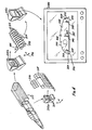
- Figure 13 shows an assembly jig 384 which corresponds to the virtual assembly jig 376. It is supported on a gantry 386 which corresponds to virtual gantry 380. Target points 388 have been located on the assembly jig 376. These correspond to the virtual target or coordinating points 378 in the file for the virtual assembly jig 376 in the data model. Located on the gantry 386 are locators 390 which correspond to the virtual locators or coordinating points 382 for the virtual gantry 380 in the data model.
- assembly jigs 392 and 394 are also supported by the gantry 386. They would also include appropriate target points for precisely locating them on the gantry with respect to one another.
- assembly jig 392 contains a drill pattern 395 which would also be laid out with precision on a virtual counterpart.
- worker scaffolding 396 is also associated with the gantry 386.
- the assembly jigs had to be rigged with the gauging master and locators positioned.
- the gauging master was removed and the locators repositioned on the rough structure. Not only did this introduce problems with respect to the re-positioning of the locators but it meant that the assembly jigs normally had to be in "aircraft orientation" since that is how the majority of the gauging masters were oriented.
- the assembly jigs can be positioned in whatever orientation it is convenient to use. This can vary from actual "aircraft orientation” to 90° rotation, or even completely rotated 180° out of phase or any other orientation. Thus, in an assembly situation such as that of Figure 13, the actual part might be located in an upside down position or at some angle. Thus, if desirable for assembly personnel or assembly robots to work in something other than "aircraft orientation", because all parts, whether they be actual aircraft parts or assembly jigs and the like, can be absolutely referenced back to "aircraft orientation" via the data model and its associated data base, any assembly orientation can be chosen.
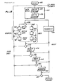
- Figure 13 shows a further view of the computer aided theodolite system 170 of Figure 3. Shown in Figure 13 is a commercial computer aided theodolite system 398, a Wild C.A.T., 2000 Coordinate Analyzing Theodolite System sold by Wild® Heerbrugg, Farmingdale, NY.
- the C.A.T. 2000 System utilizes either Wild T2000 or T220S theodolites, a Hewlett-Packard Series 200 Computer, a Hewlett-Packard Thinkjet Printer and runs Wild C.A.T. 2000 series software, part #900598, licensed from the Boeing Corporation. Attached as appendix A are copies of an operator manual, a literature brochure and a reference manual for the C.A.T. 2000 System, the entire contents of which are herein incorporated by reference.
- the theodolite system 398 has several operational modes including job setup, measure, build and inspect which are menu driven. After set up, wherein the computer 400 is turned on and the first and second theodolites, collectively identified by the numeral 402, of the system are calibrated, leveled, collimated etc., an appropriate coordinate system can be entered and stored. The theodolites 402 of the system then measure azimuth and elevation angles of selected points in space and send this information to the computer 400. The computer software converts this angular data to X, Y, Z coordinates relative to the currently established coordinate system. The software can also manipulate this data to provide other information pertinent to the measurement.
- the theodolite system 398 allows coordinates of a location to be entered.
- the theodolites 402 are then redirected until they point to that position in space. A part can now be located with respect to that position.
- the system 398 indicates the deviation of the positions the theodolites 402 are pointing to from a previously indicated set of coordinates.
- target or coordinating points for each component of a structure, a tool associated with that structure or an assembly tool utilized in conjunction with that structure are known in the file or files of the data model and are also known with respect to the engineering definition of the structure within the data model.
- these target or coordinating points can be "downloaded” to and incorporated directly on the components or associated structures by forming tangible targets or coordinating points as an integral part of each component, or group of components, or associated structure.
- the theodolite system 398 can be used to verify the relationship of one component to another by using these known coordinating points, or it can be used to position one component or associated structure with respect to a further component or further associated structure.
- target points 388 on the assembly jig 384 can be used to locate a component part with respect to the assembly jig 384, or to locate the assembly jig 384 with respect to the gantry 386 or the other assembly jigs 392 or 394.
- targets set in the assembly bay or cell are targets, collectively identified by the numeral 404.
- these are shown permanently reset into the assembly bay floor in a precisely known relationship with one another in a manner equivalent to the grids system on surfaces such as surface 288. They, thus, can serve as known coordinating points for any structure or structures which are assembled in that assembly bay.
- the targets 404 could be associated with other structure within the assembly cell such as the walls, ceiling or the like.
- the theodolite system 398 can reference these targets 404 to establish a known coordinate system. This coordinate system can then be used as a "yard stick" for referencing back to the coordinates of the engineering definition such that anything in the data model data base can be referenced in 3-D space with anything associated with the coordinate targets 404.
- the position of the locators 390 can be verified by using the theodolite system 398 and the data in the data model which defines the location of the locators 390.
- the locators 390 can quickly be audited with the theodolite system 398. This can be done in tens of minutes compared to the several days which are required when using gauging masters.
- the formation of the component parts and the construction of the gantry 386 and its associated assembly jigs 384, 392 and 394 can be started immediately upon completion of the design phase of the aircraft and does not have to wait for the formation and construction of other components.
- the formation and construction of these components can be done in parallel with other components such as the above described bonding tool 296.
- an assembly floor is also equipped with targets, collectively identified by the numeral 406, permanently recessed therein.
- targets collectively identified by the numeral 406, permanently recessed therein.
- theodolite system 408 can reference coordinating points on component parts of a fuselage section 410 of an aircraft being assembled. The coordinating points can then be referenced back to the data of the data model in the data base file to the coordinating points of an aft section 412 of the aircraft. This can be used to precisely position the aft section 412 to the fuselage section 410.
- a tool 414 is shown during assembly on a table 416.
- the near half of the tool 414 has been faired-in with plaster while the far end has been left open.
- target pins 294 have been positioned in some of the holes of the table 416. This incompletely finished tool is useful for showing several aspects of the invention.
- the theodolite system 398 can reference the target pins 294 to establish the plane of the table 416 in its memory. This can then be used to coordinate any thing associated with the table 416 with the data model definitions in its data base. Alternately, target points or coordinating points 418, 420 and 422 on profile board 424, can be used to establish a plane and to coordinate with the data model since by the above described method of formation of the profile board, these target points are also precisely known. In any event, whichever of the table 416 or the profile board 424 is used to set the coordinate system, the other can be referenced to it.
- the theodolite system 398 can also be used to check the location of each of the remaining profile boards, collectively identified by the numeral 426, one at a time as they are loaded onto the connector boards, or as a group when the assembly is finished.
- theodolite system 398 can be used to verify the surface profile of the faired-in section 428 of the tool 414.
- the surface profile of the section 428 of tool 414 is an exact image of an actual portion of the surface of an aircraft. Since utilizing the data model, a file copy from the data model data base containing the engineering definition of an aircraft part can be downloaded as for instance via a floppy disk and can be uploaded into the theodolite system 398, any point on the surface of the section 428 can be compared to its virtual image in the data model.
- plaster fairing Any deviation which might have been introduced by inappropriate assembly or fairing can be corrected to the engineering specification of the master design definition prior to perpetuation of any such deviation to actual production components. If the plaster fairing is high or low, it can be shaved or filled in as required.
- the bonding tool 432 in the manner described above, by casting the bonding tool 432 over both the tool 430, as well as portions of the table 416 including the target pins 294, the bonding tool 432 not only forms a complementary image of the tool 430 but also incorporates the hole grid 434 on the table 416 because the target pins 294 form target holes 436 in the bonding tool 432 which correspond precisely to the hole grid 434 of the table 416.
- the theodolite system 398 can audit the surface of the tool 430 and reference back to the data model, so can the theodolite system 398 audit the complementary surface 438 of the bonding tool 432.
- a virtual surface such as virtual surface 210, of the aircraft structure in the engineering definition in the data model data base is only a virtual mathematical surface which divides space and has no thickness, we can look at it from the outside like we do when we compare the surface of the tool 430 to the master design definition. However, we can also look at it from the inside and compare the complementary image of that surface on the bonding tool 432.
- This inside surface 440 of the bonding tool 298 is a complementary surface, but the data model definition does not care if we look at it from the outside in or the inside out.
- the inside surface 440 of the bonding tool 298 can be referenced back to its virtual counterpart in the data model data base file. Its virtual counterpart, of course, being the virtual surface 210. This surface 210 is the same, irrespective of whether in human terms it is looked at from the outside in or the inside out
- the holes 296 picked up from the surface 288 allow coordination of the inside surface of the bonding tool 298 back to the virtual tool 156 in the data model and from there to the virtual surface 210, which the bonding tool 298 is a tangible complementary mimic thereof.
- the known value holes 296 from the target pins 294 in the surface 288 allow for the precise placement and coordination of further precisely known target points 442 onto the inside surface 440 of the bonding tool 298.
- Coordinate points on the virtual surface 210 can be picked up and downloaded to the theodolite system 398 and then the theodolite system 398 placed in build mode and the theodolites 402 sighted.
- Reference points for the targets 442 are made by scribing, drilling and the like at the points on the inside surface 440 of the bonding tool 298 at which the theodolites are pointing.
- a theodolite equipped with a laser can be used to locate appropriate target points on any of the surfaces described. Having established the targets 442 on the inside surface of the bonding tool 298, when a composite skin panel 444 is formed against the inside surface 440 in Figure 17-a, the targets 442 are used to precisely locate the longeron 446 and spars 448 against the skin panel 444.
- the bonding tool 298 allows for direct assembly of the supporting structures (longer ones 446 and spars or stiffeners 448) onto a composite skin panel 444. It can also serve as the support structure during curing of these components in an autoclave.
- the bonding tool 298 of calcium oxide, calcium sulfate, or combinations of these two calcium slats as a matrix material, and by incorporating layers of structural fibers in this matrix, an easily constructed, inexpensive, but highly accurate and autoclaveable bonding tool is achieved.
- Suitable for the calcium oxide or calcium sulfate are UltracalTM 30 or UltracalTM 60 manufactured by United States Gypsum Company.
- Suitable as the structural fibers are layers of fiberglass mat. It has been found that fiberglass mats manufactured for use with polyester resins form a very good interface with the above noted UltracalTM products if layered in the UltracalTM product. Normally, several layers would be utilized. As for instance, 20 to 30 such layers.
- the resulting bonding tools are then used to support the skin panel 444, the longerones 446, and spars 448, during curing to form a finished component 450 which meets the engineering definition for that part as defined in the data base file of the data model.
- the bonding tool 298 can be used or cycled repeatedly for the forming and curing of identical parts.
- an audit can be made of the bonding tool 298 to verify that it still defines the proper surface parameters. Since such as audit is referenced directly back to the data model via the theodolites system 398 and not through a check tool, there is never any question whether or not the bonding tool 298 still meets the engineering specifications for the part formed on it.
- Figure 18 is a flow sheet of certain processes of the invention. These processes are initiated by logging on at 451 in an appropriate computer system and creating a file for the data model 452. Once in the data model 452, the engineering definition 454 of the aircraft structure is entered. A component portion of that engineering definition 454 is then selected and a component or surface definition 456 is created.
- the data sub set defining the surface portion 456 can then be further processed by either one of two branches which diverge at junction 458.
- a tool definition 460 is created by an operator interacting with appropriate data from the data model 452 utilizing appropriate 3-D graphics software. Having created the tool definition 460, next tool manufacturing processing steps 462 are defined. Again, this is done by the operator in conjunction with software assistance, as for instance the above noted MAXCAM software.
- the manufacturing processing steps 462 are downloaded to appropriate tooling means 464 to make the component tool parts.
- the tool definition 460 can be fed back or uploaded to the data model 452 to become an inherent adjunct part of the data model 452. Additionally, the steps outlining the manufacturing processing steps 462 for the tool can also be fed back to the data model 452 and become an inherent part of it. Having been added to the data model 452, both of these additions to the data model 452 can now be accessed as component parts of the data model 452.
- a tool can be auto defined by appropriate software, such as the above mentioned TCAD to create an auto tool definition 465.
- This auto tool definition 465 is then downloaded to further automated manufacturing software which defines automated manufacturing processing steps 466 for the formation of a tool.
- the automated manufacturing software would include software such as the above mentioned TCAD in conjunction with TCAM and MAXCAM.
- the automated manufacturing processing steps 466 are created, they are downloaded to automatic tool producing machinery represented by auto tooling means 468.
- the component parts of the tool are formed by the auto tooling means 468.
- the right hand automated branch of Figure 19 can also feed back or upload back to the data model 452 via the connector A-A.
- both the auto tool definition 464 and the automated manufacturing process steps 466 can be fed back to the data model 452 to become an inherent part of the data model 452.
- anything in the data model 452 can be downloaded to a theodolite system 470 for comparison of components.
- the tool parts either via the operator branch to the left of Figure 19 or the automated branch to the right of Figure 19, can be compared at junction 472 with appropriate coordinates which have been downloaded into the theodolite 470 from the data model 452.
- feedback can once again be made to the data model 452 to update the data model 452 as to the actual physical parameters of the tool components.
- the tool components are then assembled at assembly process step 474, and again, if desired, a comparison can be made at the junction 476 utilizing the theodolite system 470. Once again feedback can be made back to the data model 452 for input of the actual parameters of the assembled tool to the data model 452.
- a component part of the aircraft is made at process 478.
- the theodolite system 470 can again be utilized to check this component part to anything in the data model 452 at junction 480.
- the actual physical parameter of the completed part can be uploaded back to the data model 452 to become an inherent component part of the data model 452.
- the parts produced are then assembled into the final aircraft structure at assembly step 482, and the totality of the aircraft structure can again be checked at junction 484 with input from the theodolite system 470.
- the actual parameters of the completed aircraft structure can be uploaded back to the data model 452 to become an inherent component of the data model 452.
- any parameters determined from previous parts or steps, having been fed back and made an integral part of the data model 452 can be downloaded to the theodolite system 470 to audit further parts, tools, assemblies, etc., at later steps.
- an engineering definition at 454 to the final assembly, a complete history of all component parts, tools, etc., which have gone into the assembled aircraft, can be measured against their engineering definitions, and any deviation thereof can be stored as part of the data model 452 and downloaded to the theodolite system 470 as input to be used during auditing of later manufacturing steps.
Landscapes
- Engineering & Computer Science (AREA)
- Physics & Mathematics (AREA)
- General Physics & Mathematics (AREA)
- Geometry (AREA)
- Theoretical Computer Science (AREA)
- Manufacturing & Machinery (AREA)
- Automation & Control Theory (AREA)
- General Engineering & Computer Science (AREA)
- Software Systems (AREA)
- Chemical & Material Sciences (AREA)
- Quality & Reliability (AREA)
- Materials Engineering (AREA)
- Computer Graphics (AREA)
- Aviation & Aerospace Engineering (AREA)
- Mathematical Analysis (AREA)
- Mathematical Optimization (AREA)
- Pure & Applied Mathematics (AREA)
- Computer Hardware Design (AREA)
- Evolutionary Computation (AREA)
- Computational Mathematics (AREA)
- Human Computer Interaction (AREA)
- Mechanical Engineering (AREA)
- Optics & Photonics (AREA)
- Processing Or Creating Images (AREA)
- Automatic Assembly (AREA)
Applications Claiming Priority (2)
| Application Number | Priority Date | Filing Date | Title |
|---|---|---|---|
| US50794 | 1979-06-21 | ||
| US5079487A | 1987-04-14 | 1987-04-14 |
Publications (3)
| Publication Number | Publication Date |
|---|---|
| EP0290809A2 true EP0290809A2 (de) | 1988-11-17 |
| EP0290809A3 EP0290809A3 (de) | 1991-07-24 |
| EP0290809B1 EP0290809B1 (de) | 1996-04-03 |
Family
ID=21967464
Family Applications (1)
| Application Number | Title | Priority Date | Filing Date |
|---|---|---|---|
| EP88105995A Expired - Lifetime EP0290809B1 (de) | 1987-04-14 | 1988-04-14 | Herstellungssystem unter Verwendung von dreidimensionalen graphischen Modellen |
Country Status (4)
| Country | Link |
|---|---|
| EP (1) | EP0290809B1 (de) |
| JP (1) | JPS6464740A (de) |
| DE (1) | DE3855170T2 (de) |
| ES (1) | ES2086290T3 (de) |
Cited By (27)
| Publication number | Priority date | Publication date | Assignee | Title |
|---|---|---|---|---|
| FR2638999A1 (fr) * | 1988-11-15 | 1990-05-18 | Musset Claude | Procede de fabrication de maquette et dispositif de decoupe automatique d'elements pour cette fabrication |
| FR2696685A1 (fr) * | 1992-10-12 | 1994-04-15 | Aerospatiale | Procédé et dispositif d'aide à la décoration d'un objet tridimensionnel. |
| WO1997042608A1 (en) * | 1996-05-06 | 1997-11-13 | Amada Metrecs Co., Ltd. | Apparatus and method for generating a sheet-metal bend model |
| US5864482A (en) * | 1996-05-06 | 1999-01-26 | Amadasoft America, Inc. | Apparatus and method for managing distributing design and manufacturing information throughout a sheet metal production facility |
| US5886897A (en) * | 1996-05-06 | 1999-03-23 | Amada Soft America Inc. | Apparatus and method for managing and distributing design and manufacturing information throughout a sheet metal production facility |
| US5971589A (en) * | 1996-05-06 | 1999-10-26 | Amadasoft America, Inc. | Apparatus and method for managing and distributing design and manufacturing information throughout a sheet metal production facility |
| US6003588A (en) * | 1995-10-27 | 1999-12-21 | Eisenwerk Bruehl Gmbh | Process for introducing cores into a casting mold |
| EP1067479A1 (de) * | 1999-07-01 | 2001-01-10 | Tecoplan AG | Verfahren und System zur Erstellung eines aus mehreren Bauteilen bestehenden Produkts |
| WO2001088646A1 (en) * | 2000-05-17 | 2001-11-22 | Lockheed Martin Corporation | Integration of self-locating feature into detail parts |
| US7158853B2 (en) | 2004-10-25 | 2007-01-02 | Amada Company, Limited | Pattern recognition for sheet metal part models |
| WO2007034197A1 (en) * | 2005-09-22 | 2007-03-29 | Airbus Uk Limited | Assembly of aircraft components |
| US7398129B2 (en) | 2004-10-07 | 2008-07-08 | Amada Company, Limited | Representation of sheet metal part models |
| CN101391373B (zh) * | 2008-11-06 | 2010-06-02 | 沈阳飞机工业(集团)有限公司 | 数字化装配工装卡板上角材定位器安装方法 |
| US7813901B2 (en) | 2004-10-25 | 2010-10-12 | Amada Company, Limited | Sketch generator for 3D sheet metal part models created by sheet metal part feature operations |
| CN102554595A (zh) * | 2012-01-13 | 2012-07-11 | 清华大学 | 用于飞机的蒙皮制造装配系统 |
| CN103197608A (zh) * | 2013-02-27 | 2013-07-10 | 中航飞机股份有限公司西安飞机分公司 | 一种弯扭长桁数模的展开重构方法 |
| CN103272951A (zh) * | 2013-06-14 | 2013-09-04 | 沈阳飞机工业(集团)有限公司 | 切面样板交叉式模胎制造方法 |
| CN103310032A (zh) * | 2012-12-25 | 2013-09-18 | 中国航空工业集团公司沈阳飞机设计研究所 | 一种基于参数化构件的飞机结构设计方法 |
| CN106041799A (zh) * | 2016-07-08 | 2016-10-26 | 上海交通大学 | 用于大部件自动装配的六自由度定位调姿装备 |
| CN106112531A (zh) * | 2015-05-04 | 2016-11-16 | 波音公司 | 无需填隙件、定位夹具或最终孔尺寸钻模的飞行器结构组装件的装配 |
| US9857789B2 (en) | 2015-05-04 | 2018-01-02 | The Boeing Company | Model-based definition for machining aircraft parts |
| US10144530B1 (en) | 2015-05-04 | 2018-12-04 | The Boeing Company | Model-based definition for machining aircraft parts |
| CN109190157A (zh) * | 2018-07-26 | 2019-01-11 | 中国核电工程有限公司 | 一种用于Autodesk AutoCAD P&ID的对象位置信息的刷新方法 |
| RU2695017C1 (ru) * | 2018-05-22 | 2019-07-18 | Акционерное общество "АВИАСТАР-СП" | Способ динамической сборки агрегатных единиц планеров летательных аппаратов и устройство для его осуществления |
| CN111859536A (zh) * | 2020-06-22 | 2020-10-30 | 上海外高桥造船海洋工程有限公司 | 一种邮轮天幕结构的完整性建模方法 |
| CN111977018A (zh) * | 2020-07-29 | 2020-11-24 | 西安飞机工业(集团)有限责任公司 | 一种飞机机体部件装配调姿定位的支撑方法 |
| CN113334047A (zh) * | 2021-06-07 | 2021-09-03 | 四川航天长征装备制造有限公司 | 一种拼焊型管路数字化装配制造方法 |
Families Citing this family (15)
| Publication number | Priority date | Publication date | Assignee | Title |
|---|---|---|---|---|
| US6230382B1 (en) * | 1998-05-11 | 2001-05-15 | Vought Aircraft Industries, Inc. | System and method for assembling an aircraft |
| KR100453625B1 (ko) * | 2002-01-18 | 2004-10-22 | 한국항공우주산업 주식회사 | 항공기 동체 자동 연결 장치 |
| US7787979B2 (en) * | 2007-03-14 | 2010-08-31 | The Boeing Company | Splicing fuselage sections without shims |
| DE102007013499A1 (de) * | 2007-03-21 | 2008-09-25 | Bayerische Motoren Werke Aktiengesellschaft | Methodik zum Konstruieren eines technischen Gegenstands |
| GB0720704D0 (en) * | 2007-10-23 | 2007-12-05 | Airbus Uk Ltd | An aerofoil structure and a method of making a rib for an aerofoil structure |
| US8916010B2 (en) * | 2007-12-07 | 2014-12-23 | The Boeing Company | Composite manufacturing method |
| KR101115819B1 (ko) * | 2009-04-30 | 2012-03-09 | 한국항공우주산업 주식회사 | 유니버셜 플랫폼과 이를 이용한 항공기 조립 방법 |
| CN102001451B (zh) * | 2010-11-12 | 2013-05-29 | 浙江大学 | 基于四个数控定位器、调姿平台和移动托架的飞机部件调姿、对接系统及方法 |
| US20130015596A1 (en) * | 2011-06-23 | 2013-01-17 | Irobot Corporation | Robotic fabricator |
| EP2980736A1 (de) | 2014-07-28 | 2016-02-03 | PFW Aerospace GmbH | Verfahren zur Herstellung eines Objekts, welches aus einer Vielzahl von Einzelteilen besteht, Konstruktionsmodul und Fertigungssystem |
| EP3508430A1 (de) * | 2015-03-23 | 2019-07-10 | Bombardier Inc. | Simulieren der belastung von flugzeugstrukturen während einer flugzeugmontage |
| JP6513584B2 (ja) * | 2016-02-02 | 2019-05-15 | 三菱重工業株式会社 | 保持治具固定装置 |
| CN105710625A (zh) * | 2016-04-25 | 2016-06-29 | 北京卫星环境工程研究所 | 狭小空间六自由度大重量设备调姿装配装置 |
| CN108509748B (zh) * | 2018-04-17 | 2022-05-03 | 江西洪都商用飞机股份有限公司 | 一种飞机装配型架内型板快速设计方法 |
| US11731788B2 (en) * | 2019-05-23 | 2023-08-22 | Bae Systems Plc | Method and apparatus for producing at least part of a structural frame of a vehicle |
Family Cites Families (7)
| Publication number | Priority date | Publication date | Assignee | Title |
|---|---|---|---|---|
| PH14838A (en) * | 1974-03-21 | 1981-12-16 | Procter & Gamble | Detergent composition |
| DE3066202D1 (en) * | 1979-11-03 | 1984-02-23 | Procter & Gamble | Granular laundry compositions |
| JPS56102455A (en) * | 1980-01-16 | 1981-08-15 | Agency Of Ind Science & Technol | Composite production system |
| IN161821B (de) * | 1981-02-26 | 1988-02-06 | Colgate Palmolive Co | |
| ZA851897B (en) * | 1984-04-02 | 1986-10-29 | Colgate Palmolive Co | Non-caking bleaching detergent composition containing a lower hydrate of sodium perborate |
| JPS61249235A (ja) * | 1985-04-26 | 1986-11-06 | Toshiba Corp | 組立システム用辞書および組立システム構築装置 |
| JPH0623258B2 (ja) * | 1986-10-07 | 1994-03-30 | 日本ペイント株式会社 | 親水性多孔粒子 |
-
1988
- 1988-04-14 JP JP63092623A patent/JPS6464740A/ja active Pending
- 1988-04-14 ES ES88105995T patent/ES2086290T3/es not_active Expired - Lifetime
- 1988-04-14 EP EP88105995A patent/EP0290809B1/de not_active Expired - Lifetime
- 1988-04-14 DE DE3855170T patent/DE3855170T2/de not_active Expired - Fee Related
Non-Patent Citations (3)
| Title |
|---|
| ELECTRONIC DESIGN, vol. 30, no. 21, October 1982, pages 225-236, Waseca, MN, Denville, NJ, US; M. SCHLINDER: Systems & Software; "CAD/CAM systems shape up for total automation" * |
| IBM TECHNICAL DISCLOSURE BULLETIN, vol. 16, no. 5, October 1973, pages 1628-1629, New York, US; P.A. SCHUMANN et al.: "Manufacturing piece part inspection design system" * |
| MACHINE DESIGN, vol. 56, no. 2, January 1984, pages 40-44, Cleveland, Ohio, US; G.D. HODSON: "CAT/CAM takes the guesswork out of mold-making" * |
Cited By (53)
| Publication number | Priority date | Publication date | Assignee | Title |
|---|---|---|---|---|
| EP0369909A1 (de) * | 1988-11-15 | 1990-05-23 | Claude Paul Musset | Verfahren zum Herstellen von Modellen und automatische Schneidevorrichtung für diese Herstellung |
| FR2638999A1 (fr) * | 1988-11-15 | 1990-05-18 | Musset Claude | Procede de fabrication de maquette et dispositif de decoupe automatique d'elements pour cette fabrication |
| FR2696685A1 (fr) * | 1992-10-12 | 1994-04-15 | Aerospatiale | Procédé et dispositif d'aide à la décoration d'un objet tridimensionnel. |
| EP0593340A1 (de) * | 1992-10-12 | 1994-04-20 | AEROSPATIALE Société Nationale Industrielle | Verfahren und Vorrichtung zur Erleichterung der Dekoration eines dreidimensionalen Gegenstandes |
| US5490080A (en) * | 1992-10-12 | 1996-02-06 | Aerospatiale Societe Nationale Industrielle | Method and device for decorating a tridimensional object |
| US6003588A (en) * | 1995-10-27 | 1999-12-21 | Eisenwerk Bruehl Gmbh | Process for introducing cores into a casting mold |
| US6411862B1 (en) | 1996-05-06 | 2002-06-25 | Amada Company, Ltd. | Apparatus and method for managing and distributing design and manufacturing information throughout a sheet metal production facility |
| US6219586B1 (en) | 1996-05-06 | 2001-04-17 | Amadasoft America, Inc. | Apparatus and method for managing and distributing design and manufacturing information throughout a sheet metal production facility |
| US5886897A (en) * | 1996-05-06 | 1999-03-23 | Amada Soft America Inc. | Apparatus and method for managing and distributing design and manufacturing information throughout a sheet metal production facility |
| US5971589A (en) * | 1996-05-06 | 1999-10-26 | Amadasoft America, Inc. | Apparatus and method for managing and distributing design and manufacturing information throughout a sheet metal production facility |
| US5828575A (en) * | 1996-05-06 | 1998-10-27 | Amadasoft America, Inc. | Apparatus and method for managing and distributing design and manufacturing information throughout a sheet metal production facility |
| US6065857A (en) * | 1996-05-06 | 2000-05-23 | Amadasoft America, Inc. | Computer readable medium for managing and distributing design and manufacturing information throughout a sheet metal production facility |
| US7266419B2 (en) | 1996-05-06 | 2007-09-04 | Amada Company, Limited | Search for similar sheet metal part models |
| US6185476B1 (en) | 1996-05-06 | 2001-02-06 | Amada Soft America, Inc. | Apparatus and method for managing and distributing design and manufacturing information throughout a sheet metal production facility |
| US6212441B1 (en) | 1996-05-06 | 2001-04-03 | Amadasoft America, Inc. | Apparatus and method for managing and distributing design and manufacturing information throughout a sheet metal production facility |
| US5864482A (en) * | 1996-05-06 | 1999-01-26 | Amadasoft America, Inc. | Apparatus and method for managing distributing design and manufacturing information throughout a sheet metal production facility |
| WO1997042608A1 (en) * | 1996-05-06 | 1997-11-13 | Amada Metrecs Co., Ltd. | Apparatus and method for generating a sheet-metal bend model |
| US6327514B1 (en) | 1996-05-06 | 2001-12-04 | Amadasoft America, Inc. | Apparatus and method for managing and distributing design and manufacturing information throughout a sheet metal production facility |
| US7197372B2 (en) | 1996-05-06 | 2007-03-27 | Amada Company, Limited | Apparatus and method for managing and distributing design and manufacturing information throughout a sheet metal production facility |
| EP1067479A1 (de) * | 1999-07-01 | 2001-01-10 | Tecoplan AG | Verfahren und System zur Erstellung eines aus mehreren Bauteilen bestehenden Produkts |
| US6496745B1 (en) | 2000-05-17 | 2002-12-17 | Lockheed Martin Corporation | Integration of self-locating feature into detail parts |
| WO2001088646A1 (en) * | 2000-05-17 | 2001-11-22 | Lockheed Martin Corporation | Integration of self-locating feature into detail parts |
| US7398129B2 (en) | 2004-10-07 | 2008-07-08 | Amada Company, Limited | Representation of sheet metal part models |
| US7158853B2 (en) | 2004-10-25 | 2007-01-02 | Amada Company, Limited | Pattern recognition for sheet metal part models |
| US7813901B2 (en) | 2004-10-25 | 2010-10-12 | Amada Company, Limited | Sketch generator for 3D sheet metal part models created by sheet metal part feature operations |
| CN101272956B (zh) * | 2005-09-22 | 2012-06-06 | 空中客车英国运营有限责任公司 | 飞行器部件的组装 |
| WO2007034197A1 (en) * | 2005-09-22 | 2007-03-29 | Airbus Uk Limited | Assembly of aircraft components |
| US8479394B2 (en) | 2005-09-22 | 2013-07-09 | Airbus Operations Limited | Assembly of aircraft components |
| CN101391373B (zh) * | 2008-11-06 | 2010-06-02 | 沈阳飞机工业(集团)有限公司 | 数字化装配工装卡板上角材定位器安装方法 |
| CN102554595A (zh) * | 2012-01-13 | 2012-07-11 | 清华大学 | 用于飞机的蒙皮制造装配系统 |
| CN103310032B (zh) * | 2012-12-25 | 2016-09-28 | 中国航空工业集团公司沈阳飞机设计研究所 | 一种基于参数化构件的飞机结构设计方法 |
| CN103310032A (zh) * | 2012-12-25 | 2013-09-18 | 中国航空工业集团公司沈阳飞机设计研究所 | 一种基于参数化构件的飞机结构设计方法 |
| CN103197608A (zh) * | 2013-02-27 | 2013-07-10 | 中航飞机股份有限公司西安飞机分公司 | 一种弯扭长桁数模的展开重构方法 |
| CN103272951A (zh) * | 2013-06-14 | 2013-09-04 | 沈阳飞机工业(集团)有限公司 | 切面样板交叉式模胎制造方法 |
| CN103272951B (zh) * | 2013-06-14 | 2016-01-20 | 沈阳飞机工业(集团)有限公司 | 切面样板交叉式模胎制造方法 |
| EP3093723A1 (de) * | 2015-05-04 | 2016-11-16 | The Boeing Company | Montage einer flugzeugstrukturanordnung ohne shimming, spannvorrichtungen oder bohrlehren mit endgültiger bohrlochgrösse |
| CN106112531A (zh) * | 2015-05-04 | 2016-11-16 | 波音公司 | 无需填隙件、定位夹具或最终孔尺寸钻模的飞行器结构组装件的装配 |
| US10899476B1 (en) | 2015-05-04 | 2021-01-26 | The Boeing Company | Model-based definition for machining aircraft parts |
| US10520921B2 (en) | 2015-05-04 | 2019-12-31 | The Boeing Company | Model-based definition for machining aircraft parts |
| US9857789B2 (en) | 2015-05-04 | 2018-01-02 | The Boeing Company | Model-based definition for machining aircraft parts |
| US9925625B2 (en) | 2015-05-04 | 2018-03-27 | The Boeing Company | Assembly of an aircraft structure assembly without shimming, locating fixtures or final-hole-size drill jigs |
| US10144530B1 (en) | 2015-05-04 | 2018-12-04 | The Boeing Company | Model-based definition for machining aircraft parts |
| US10160070B2 (en) | 2015-05-04 | 2018-12-25 | The Boeing Company | Method for assembling an aircraft structure assembly without use of any of shimming, locating fixtures and final-hole-size drill jigs |
| CN106112531B (zh) * | 2015-05-04 | 2020-05-29 | 波音公司 | 无需填隙件、定位夹具或最终孔尺寸钻模的飞行器结构组装件的装配 |
| EP3611586A1 (de) * | 2015-05-04 | 2020-02-19 | The Boeing Company | Montage einer flugzeugstrukturbaugruppe ohne shimming, spannvorrichtungen oder bohrlehren mit endgültiger bohrlochgrösse |
| CN106041799B (zh) * | 2016-07-08 | 2018-01-02 | 上海交通大学 | 用于大部件自动装配的六自由度定位调姿装备 |
| CN106041799A (zh) * | 2016-07-08 | 2016-10-26 | 上海交通大学 | 用于大部件自动装配的六自由度定位调姿装备 |
| RU2695017C1 (ru) * | 2018-05-22 | 2019-07-18 | Акционерное общество "АВИАСТАР-СП" | Способ динамической сборки агрегатных единиц планеров летательных аппаратов и устройство для его осуществления |
| CN109190157A (zh) * | 2018-07-26 | 2019-01-11 | 中国核电工程有限公司 | 一种用于Autodesk AutoCAD P&ID的对象位置信息的刷新方法 |
| CN111859536A (zh) * | 2020-06-22 | 2020-10-30 | 上海外高桥造船海洋工程有限公司 | 一种邮轮天幕结构的完整性建模方法 |
| CN111859536B (zh) * | 2020-06-22 | 2023-12-08 | 上海外高桥造船海洋工程有限公司 | 一种邮轮天幕结构的完整性建模方法 |
| CN111977018A (zh) * | 2020-07-29 | 2020-11-24 | 西安飞机工业(集团)有限责任公司 | 一种飞机机体部件装配调姿定位的支撑方法 |
| CN113334047A (zh) * | 2021-06-07 | 2021-09-03 | 四川航天长征装备制造有限公司 | 一种拼焊型管路数字化装配制造方法 |
Also Published As
| Publication number | Publication date |
|---|---|
| DE3855170D1 (de) | 1996-05-09 |
| EP0290809B1 (de) | 1996-04-03 |
| EP0290809A3 (de) | 1991-07-24 |
| ES2086290T3 (es) | 1996-07-01 |
| DE3855170T2 (de) | 1996-10-17 |
| JPS6464740A (en) | 1989-03-10 |
Similar Documents
| Publication | Publication Date | Title |
|---|---|---|
| EP0290809B1 (de) | Herstellungssystem unter Verwendung von dreidimensionalen graphischen Modellen | |
| US5023800A (en) | Assembly data model system | |
| US4945488A (en) | Integrated aircraft manufacturing system | |
| US5033014A (en) | Integrated manufacturing system | |
| US5106290A (en) | Assembly data model tool system | |
| US4937768A (en) | Integrated assembly system | |
| US4956764A (en) | Assembly data model tool system | |
| US11370563B2 (en) | Method and system for joining structures | |
| US9958854B2 (en) | Systems and methods for robotic measurement of parts | |
| DE69732905T2 (de) | Verfahren zur verbesserung der genauigkeit von maschinen | |
| CN106112531A (zh) | 无需填隙件、定位夹具或最终孔尺寸钻模的飞行器结构组装件的装配 | |
| Lee et al. | CASCAM—an automated system for sculptured surface cavity machining | |
| EP2276607A1 (de) | Verfahren und system zur erstellung der flugbahn eines luftfahrzeugs | |
| Elser et al. | On achieving accuracy and efficiency in Additive Manufacturing: Requirements on a hybrid CAM system | |
| US20020166220A1 (en) | Process for repairing a structure | |
| Chen et al. | A framework of measurement assisted assembly for wing-fuselage alignment based on key measurement characteristics | |
| US7421363B2 (en) | Method for virtual inspection of virtually machined parts | |
| US6661930B1 (en) | Method for nesting a computer model of a part with a computer model of a fixture | |
| Sarma et al. | Rapid product realization from detail design | |
| Bennulf et al. | Verification and deployment of automatically generated robot programs used in prefabrication of house walls | |
| Zou et al. | An off‐line programming system for flexible drilling of aircraft wing structures | |
| Yuan et al. | Robotic fabrication of structural performance-based timber gridshell in large-scale building scenario | |
| Kihlman et al. | Low-cost automation for aircraft assembly | |
| Landers et al. | Reconfigurable manufacturing equipment | |
| Price | Virtual Product Development-Case study of the T-45 horizontal stabilator |
Legal Events
| Date | Code | Title | Description |
|---|---|---|---|
| PUAI | Public reference made under article 153(3) epc to a published international application that has entered the european phase |
Free format text: ORIGINAL CODE: 0009012 |
|
| AK | Designated contracting states |
Kind code of ref document: A2 Designated state(s): DE ES FR GB SE |
|
| PUAL | Search report despatched |
Free format text: ORIGINAL CODE: 0009013 |
|
| AK | Designated contracting states |
Kind code of ref document: A3 Designated state(s): DE ES FR GB SE |
|
| RHK1 | Main classification (correction) |
Ipc: G06F 15/60 |
|
| 17P | Request for examination filed |
Effective date: 19911212 |
|
| 17Q | First examination report despatched |
Effective date: 19940630 |
|
| GRAH | Despatch of communication of intention to grant a patent |
Free format text: ORIGINAL CODE: EPIDOS IGRA |
|
| RAP1 | Party data changed (applicant data changed or rights of an application transferred) |
Owner name: NORTHROP GRUMMAN CORPORATION |
|
| GRAA | (expected) grant |
Free format text: ORIGINAL CODE: 0009210 |
|
| AK | Designated contracting states |
Kind code of ref document: B1 Designated state(s): DE ES FR GB SE |
|
| REF | Corresponds to: |
Ref document number: 3855170 Country of ref document: DE Date of ref document: 19960509 |
|
| ET | Fr: translation filed | ||
| REG | Reference to a national code |
Ref country code: ES Ref legal event code: FG2A Ref document number: 2086290 Country of ref document: ES Kind code of ref document: T3 |
|
| PLBE | No opposition filed within time limit |
Free format text: ORIGINAL CODE: 0009261 |
|
| STAA | Information on the status of an ep patent application or granted ep patent |
Free format text: STATUS: NO OPPOSITION FILED WITHIN TIME LIMIT |
|
| PGFP | Annual fee paid to national office [announced via postgrant information from national office to epo] |
Ref country code: FR Payment date: 19970318 Year of fee payment: 10 |
|
| PGFP | Annual fee paid to national office [announced via postgrant information from national office to epo] |
Ref country code: SE Payment date: 19970319 Year of fee payment: 10 |
|
| PGFP | Annual fee paid to national office [announced via postgrant information from national office to epo] |
Ref country code: DE Payment date: 19970324 Year of fee payment: 10 |
|
| 26N | No opposition filed | ||
| PGFP | Annual fee paid to national office [announced via postgrant information from national office to epo] |
Ref country code: GB Payment date: 19970326 Year of fee payment: 10 |
|
| PGFP | Annual fee paid to national office [announced via postgrant information from national office to epo] |
Ref country code: ES Payment date: 19970421 Year of fee payment: 10 |
|
| PG25 | Lapsed in a contracting state [announced via postgrant information from national office to epo] |
Ref country code: GB Free format text: LAPSE BECAUSE OF NON-PAYMENT OF DUE FEES Effective date: 19980414 |
|
| PG25 | Lapsed in a contracting state [announced via postgrant information from national office to epo] |
Ref country code: SE Free format text: LAPSE BECAUSE OF NON-PAYMENT OF DUE FEES Effective date: 19980415 Ref country code: ES Free format text: LAPSE BECAUSE OF NON-PAYMENT OF DUE FEES Effective date: 19980415 |
|
| PG25 | Lapsed in a contracting state [announced via postgrant information from national office to epo] |
Ref country code: FR Free format text: THE PATENT HAS BEEN ANNULLED BY A DECISION OF A NATIONAL AUTHORITY Effective date: 19980430 |
|
| GBPC | Gb: european patent ceased through non-payment of renewal fee |
Effective date: 19980414 |
|
| EUG | Se: european patent has lapsed |
Ref document number: 88105995.0 |
|
| PG25 | Lapsed in a contracting state [announced via postgrant information from national office to epo] |
Ref country code: DE Free format text: LAPSE BECAUSE OF NON-PAYMENT OF DUE FEES Effective date: 19990202 |
|
| REG | Reference to a national code |
Ref country code: FR Ref legal event code: ST |
|
| REG | Reference to a national code |
Ref country code: ES Ref legal event code: FD2A Effective date: 20010503 |