EP0289981B1 - Cable sleeve made of plastics material with resilient sealing elements in the sealing areas - Google Patents
Cable sleeve made of plastics material with resilient sealing elements in the sealing areas Download PDFInfo
- Publication number
- EP0289981B1 EP0289981B1 EP88107034A EP88107034A EP0289981B1 EP 0289981 B1 EP0289981 B1 EP 0289981B1 EP 88107034 A EP88107034 A EP 88107034A EP 88107034 A EP88107034 A EP 88107034A EP 0289981 B1 EP0289981 B1 EP 0289981B1
- Authority
- EP
- European Patent Office
- Prior art keywords
- longitudinal
- sealing
- cable sleeve
- seal
- sleeve according
- Prior art date
- Legal status (The legal status is an assumption and is not a legal conclusion. Google has not performed a legal analysis and makes no representation as to the accuracy of the status listed.)
- Expired - Lifetime
Links
Images


Classifications
-
- H—ELECTRICITY
- H02—GENERATION; CONVERSION OR DISTRIBUTION OF ELECTRIC POWER
- H02G—INSTALLATION OF ELECTRIC CABLES OR LINES, OR OF COMBINED OPTICAL AND ELECTRIC CABLES OR LINES
- H02G15/00—Cable fittings
- H02G15/013—Sealing means for cable inlets
-
- H—ELECTRICITY
- H02—GENERATION; CONVERSION OR DISTRIBUTION OF ELECTRIC POWER
- H02G—INSTALLATION OF ELECTRIC CABLES OR LINES, OR OF COMBINED OPTICAL AND ELECTRIC CABLES OR LINES
- H02G15/00—Cable fittings
- H02G15/08—Cable junctions
- H02G15/10—Cable junctions protected by boxes, e.g. by distribution, connection or junction boxes
- H02G15/113—Boxes split longitudinally in main cable direction
Definitions
- the invention relates to a cable sleeve with front sealing bodies and a longitudinally divided sleeve body, the latter being applied to the sealing body via elastic, endless ring seals and in which an elastic longitudinal seal is used in the longitudinal closure area, the endless ring seals in circumferential grooves of the front sealing body and the longitudinal seal are inserted in a longitudinal groove and that in the crossing areas of the ring and longitudinal seals in the inner groove wall of the longitudinal edge of the longitudinal groove in each case a recess is made through which the longitudinal seal protrudes with a protrusion directed against the ring seal.
- the sealing elements designed as a longitudinal seal consist of foamed, silicone rubber, such as a highly polymeric, crosslinked polysiloxane with possibly built-in inorganic fillers, in which there is predominantly a closed-cell pore structure that the plastic material for the sealing elements, preferably the longitudinal seal, has a Shore hardness of 15 to 40, and that the longitudinal seal in each case in the crossing areas of the ring and longitudinal seals has an approach that corresponds to the recess in shape, but inside survives.
- the seal is usually used for cable entries, as well as for the parting planes of the sealing bodies on the front Made with a plastic sealant, as there are no major problems in these areas.
- the seal looks different in the joints between the sealing bodies and the socket pipe, as well as in the longitudinal area of the separation slot, because here the use of elastic sealing material due to the requirement repeated opening is desired.
- the major problem areas of such a sealing system are the crossing points of round and longitudinal seals, especially because of the movements at these points.
- the longitudinal seal in the area of the crossing points is pressed into the groove and compressed until the elastic force is equal to the pneumatic force.
- the foam material of the longitudinal seal must be hard enough to withstand the required pressure. Elastic silicone foams with a Shore hardness of about 15 to 40 are suitable for this, for example, which have about 25% compression per 1 bar differential pressure.
- the round seal must press the longitudinal seal into the groove, so it must be stronger.
- the round cross-section of the round seal is very suitable because the surface contact is relatively small and therefore relatively high surface pressure arises.
- a common round seal made of silicone tubing with 3 mm compression and 11 N / running centimeter brings about 6 bar surface pressure, which increases due to the internal pressure of the sleeve.
- the plastic material for the sealing elements according to the invention is preferably a high-polymer, crosslinked polysiloxane produced by using blowing agents, possibly with built-in inorganic fillers. It is also characterized by a predominantly closed-cell pore structure and can be used both with a smooth outer skin and as a cut material with the appropriate structuring.
- the plastic material has excellent heat and cold resistance and retains its elastic properties down to about - 60 ° C.
- Figure 1 shows the cable sleeve according to the invention in principle, whereby it is indicated that here as a sleeve body, a simply longitudinally slotted sleeve pipe 1 is drawn onto the two end sealing bodies 10.
- Each of the two sealing bodies 10 has a circumferential sealing groove, into which an endless ring seal 7 of the type described above is inserted.
- the sealing bodies 10 are divided, for example, and that cable entry openings for the introduction of cables K can be introduced in the division plane.
- the sleeve pipe 1 has along its longitudinal edges 2 and 4 a sealing system which consists of a longitudinal groove 3 along one longitudinal edge 2 and a matching sealing spring 5 along the second longitudinal edge 4.
- the longitudinal seal 6 is inserted into the longitudinal groove 3, as will be explained in more detail below.
- Closure elements for example a closing rail, are drawn over the protruding, undercut longitudinal edges 2 and 4, with which the necessary closing pressure is generated in the sealing areas.
- the longitudinal edges 2 and 4 like the associated closing rail, are preferably wedge-shaped, which considerably simplifies the closing process.
- Figure 2 shows the intersection of an annular seal 7, which is shown here in dashed lines, and the longitudinal seal 6 along the longitudinal edges 2 and 4 of the sleeve pipe 1. It is shown that the inner groove wall 8 of the longitudinal edge 2 in the area of the circumferential ring seal 7 one Has recess 12, through which a projection 11 of the longitudinal seal 6 protrudes with a small projection and thus presses against the ring seal 7. In contrast, the sealing spring 5 of the second longitudinal edge 4 has an extension 13 at this point, which fits into the recess 12 of the opposite longitudinal edge 2 and thus serves as a counter bearing for the extension 11 of the longitudinal seal 6. This ensures that direct contact of the sealing elements can take place at the intersection of the longitudinal and ring seals (6, 7), so that the desired secure sealing can be achieved in connection with the properties of the sealing elements described above.
- FIG. 3 shows the view III-III indicated in FIG. 2 and explains the conditions in the endangered crossing point.
- the ring seal 7, which is designed as a hose, is inserted into the circumferential sealing groove 9 of the sealing body 10 and that it is pressed into the elastic extension 11 of the longitudinal seal 6 without any gusset formation is, as already explained above, the ring seal 7 is harder than the longitudinal seal 6.
- a further measure for sealing in this area is to wet the sealing elements at least in these areas with a conventional plastic sealing paste, preferably based on synthetic rubber , which further supports the sealing effect.
- Figure 4 shows a second embodiment for the formation of the intersection of the longitudinal and ring seals (6, 7).
- the sealing groove is laid in a bend 14 so far outward beyond the groove edge 8 until the longitudinal seal 6 is directed against the ring seal 7 with sufficient protrusion.
- the missing groove wall 8 in this area corresponds to the recess 12 in the previous embodiment. Otherwise the conditions are the same.
- FIGS. 5 to 7 show exemplary embodiments of longitudinal seals in the areas of the crossing points.
- a longitudinal seal 6 with a square cross-section is shown, the shoulder 11 being integrally formed.
- Such a seal like the associated longitudinal groove, is preferably slightly trapezoidal in cross section, so that the insertion of the seal is facilitated.
- FIG. 6 shows a longitudinal seal 6a with a quadrangular cross-section, the shoulder 11a being subsequently used as a separate part. This has the advantage that any lengths of longitudinal seals can be cut from the piece. The approach 11a can then be fixed to the longitudinal seal, for example by gluing.
- Figure 7 shows only the difference compared to the embodiment of Figure 6 that a round profile 6b is used with a matched approach 11b.
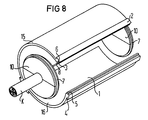
- FIG. 8 additionally shows a cable sleeve, the sleeve body of which is formed from two half-shells 15 and 16. According to the invention, the measures already described above are also carried out at the crossing points of the second dividing line, so that the same conditions result. This eliminates the need for further explanations.
- the advantage of the embodiment of sealing areas in the crossing points of elastic sealing elements according to the invention is that the leakages that may occur in the gusset areas between the sealing elements and the socket pipe edges are avoided. This is done with the help of profiles on the corresponding sealing edges, as will be explained in more detail below.
- the critical conditions are shown schematically in FIGS. 16, 17 and 18, as currently shown in the prior art.
- a sealing element 6 is placed in a longitudinal groove between the two longitudinal edges 2 and 4 of a cable sleeve, as the left part of FIG. 16 shows.
- the elastic sealing element 6 is deformed in such a way that a protruding tip results.
- a second sealing element 7, for example an annular seal the sealing element 6 is pressed into the longitudinal groove, but gusset areas 18 arise along the two longitudinal edges 2 and 4 and the longitudinal seal, so that here there are leaks in the longitudinal direction.
- a second sealing element 7 for example an annular seal
- FIG. 17 now shows a sealing element 6a, which is thicker than the longitudinal groove between the two longitudinal edges 2 and 4, so that it protrudes beyond the edge of the sealing groove in the open state.
- ear-shaped protuberances 19 are formed along the longitudinal edges 2 and 4, as shown in the middle part of FIG. 17, at the ends of which longitudinal gusset regions 18 are formed, since the transition jump of the protuberances 19 is not completely filled by the ring seal 7 can be.
- leaks in the longitudinal direction can also be expected in such an embodiment.
- FIG. 18 an example is shown in which a sealing element 6b is inserted into the longitudinal groove between the two longitudinal edges 2 and 4 is inserted, which is thinner than the depth of the longitudinal groove.
- the sealing element 6b is laterally pressed, as shown in the middle part of FIG.
- leaky gusset areas 18 are formed by pressure from a second sealing element 7 lying above it.
- FIG. 9 shows a cable sleeve according to the invention in principle, whereby it is indicated that a longitudinally slotted sleeve pipe 1 is drawn onto the two end sealing bodies with the ring seal 7 as the sleeve body.
- Each of the two known sealing bodies on the end faces of the cable sleeve 1 has a circumferential sealing groove, into which an endless ring seal 7 is inserted.
- This ring seal 7 can be tubular or consist of foamed plastic material such as the longitudinal seal 6. From this figure, the intersection of the ring seal 7, which is shown here in dashed lines, and the longitudinal seal 6 along the longitudinal edges 2 and 4 of the socket pipe 1 is particularly evident.
- the inner groove wall 8 of the longitudinal edge 2 has a recess 12 in the area of the circumferential ring seal 7, through which an extension 11 of the longitudinal seal 6 projects with a slight overhang and thus presses against the ring seal 7, as explained in detail in the preceding description is.
- the sealing spring 5 of the second longitudinal edge 4 has an extension 13 which fits into the recess 12 of the opposite longitudinal edge 2 and thus serves as a counter bearing for the projection 11 of the longitudinal seal 6. This ensures that the sealing elements can come into direct contact at the intersection of the longitudinal and ring seals.
- these sealing edges 17 are provided with suitable profiles along the recess 12 as well as the extension 13, so that there are alternative cavities for the elastic sealing element. In this way, the tolerance cases for seals, as described above as the prior art, can now be fully captured. If one now considers the conditions as indicated in FIG. 18 in connection with the profiling 20 of the sealing edges 17, it can be shown that the extension 11 of the longitudinal seal 6 penetrates into the profilings and pulls up at the edges of the profiling. As a result, no longitudinal gussets can form, so that there is an excellent sealing effect in the longitudinal direction.
- FIG. 10 shows a cross section through the longitudinal edges 2 and 4 of the cable sleeve 1 in the region of the intersection of the longitudinal and ring seals.
- the longitudinal groove 3, which is interrupted inwards by the cutout 12, is clearly shown here.
- On the inner edge of the recess 12 is the critical sealing edge 17, in which incisions in the profile 20 are indicated.
- the same conditions are given on the longitudinal edge 4, where the sealing spring 5 is provided with the extension 13 in the region of the recess 12.
- the critical sealing edge 17 is again on the inner edge of the extension 13 to see with the indicated profiling 16. This illustration shows the still open state of the longitudinal lock.
- FIG. 11 now shows the relationship of the longitudinal closure according to FIG. 2 in the closed state with the longitudinal seal 6 inserted.
- the lateral compression of the longitudinal seal 6 causes the shoulder 11 to be raised inwards against the ring seal (not shown here). This would result in conditions such as those described in the described prior art if the profiles 20 according to the invention were not arranged along the sealing edges.
- the ring seal is not shown here.
- View V is also indicated for the following FIG. 13.
- FIG. 12 now shows a view of the sealing system in the region of the intersection of the longitudinal seal 6 with the shoulder 11 and the ring seal 7.
- the profiles 20 arranged along the sealing edges 17 are clearly recognizable, by means of which a secure sealing in the longitudinal direction according to the invention is achieved.
- FIG. 13 now shows the view of a sealing edge 17 as indicated by V in FIG. 3.
- angular notches are selected, the distance between two notch edges preferably being approximately 3 mm.
- the depth of these notches is matched to the hardness of the elastic seals used in order to achieve optimal conditions.
- both the sealing edge 17 and the edges of the profiles themselves can be adapted accordingly to the materials used, from sharp-edged to rounded.
- FIG. 14 shows a part of a sealing edge 17 in which the profiling 20a is produced by means of rounded incisions is.
- profiling 20a is produced by means of rounded incisions is.
- other types of profiling can also be incorporated into the sealing edges 17 with the same mode of action.
- FIG. 15 shows an exemplary embodiment according to the invention, in which it is indicated in a top view that a foamed plastic material can also be used for the ring seal 7a, as in the case of the longitudinal seal 6.
- This ring seal 7a is embedded in the circumferential sealing groove 9 of the sealing body 10 and is pressed sealingly against the recess 11 of the longitudinal seal 6.
Description
Die Erfindung betrifft eine Kabelmuffe mit stirnseitigen Dichtungskörpern und einem längsgeteilten Muffenkörper, wobei letzterer über elastische, endlose Ringdichtungen auf die Dichtungskörper aufgebracht ist und bei der im längsseitigen Verschlußbereich eine elastische Längsdichtung eingesetzt ist, wobei die endlosen Ringdichtungen in umlaufenden Nuten der stirnseitigen Dichtungskörper und die Längsdichtung in einer Längsnut eingelegt sind und daß in den Kreuzungsbereichen der Ring- und Längsdichtungen in der inneren Nutwand des Längsrandes der Längsnut jeweils eine Aussparung eingebracht ist, durch welche die Längsdichtung mit einem gegen die Ringdichtung gerichteten Überstand hindurchragt.The invention relates to a cable sleeve with front sealing bodies and a longitudinally divided sleeve body, the latter being applied to the sealing body via elastic, endless ring seals and in which an elastic longitudinal seal is used in the longitudinal closure area, the endless ring seals in circumferential grooves of the front sealing body and the longitudinal seal are inserted in a longitudinal groove and that in the crossing areas of the ring and longitudinal seals in the inner groove wall of the longitudinal edge of the longitudinal groove in each case a recess is made through which the longitudinal seal protrudes with a protrusion directed against the ring seal.
Aus der DE-OS 35 36 599 sind Kabelmuffen der obengenannten Art bekannt, bei denen Dichtungssysteme aus Ringdichtungen in den stirnseitigen Dichtungskörpern und Längsdichtungen in der Trennungslinie des geschlitzten Muffenrohres verwendet werden. Solche voneinander getrennte Dichtungen bereiten in den Kreuzungspunkten erhebliche Schwierigkeiten, die nicht immer optimal zu lösen sind, so daß dort immer Dichtungsprobleme auftreten. Ähnliche Verhältnisse treten auch bei Kabelmuffen aus Halbschalen auf.From DE-OS 35 36 599 cable sleeves of the type mentioned above are known, in which sealing systems made of ring seals in the front sealing bodies and longitudinal seals are used in the dividing line of the slotted sleeve pipe. Such seals, which are separate from one another, cause considerable difficulties at the crossing points, which cannot always be solved optimally, so that there are always sealing problems. Similar conditions also occur with cable sleeves made from half shells.
Aus der DE-A-35 12 165 ist eine Kabelmuffe mit stirnseitigen Dichtungskörpern bekannt, bei denen Ringdichtungen in umlaufenden Nuten eingelegt sind. Außerdem wird eine Längsdichtung verwendet, welche durch Ausübung von Kräften durch das Verschlußsystem nach innen durch ein Fenster bewegt wird, das zwischen sich gegenüberliegenden Innenwänden von Deckeln gebildet ist. Hier wird also durch die Verformung der Längsdichtung versucht, eine Abdichtung zu den Ringdichtungen zu erreichen, wobei die Längsdichtungen in den kritischen Punkten mehr belastet werden.From DE-A-35 12 165 a cable sleeve with front sealing bodies is known, in which ring seals are inserted in circumferential grooves. In addition, a longitudinal seal is used, which is moved inward through the closure system by exerting forces through a window which is formed between opposite inner walls of covers. Here, therefore, the deformation of the longitudinal seal tries to achieve a seal with the ring seals, the Longitudinal seals in the critical points are loaded more.
So ist nun Aufgabe der vorliegenden Erfindung, die Kreuzungsbereiche von getrennt geführten Dichtungen zu optimieren. Die gestellte Aufgabe wird nun mit einer Kabelmuffe der oben beschriebenen Art dadurch gelöst, daß zumindest die als Längsdichtung ausgebildeten Dichtungselemente aus geschäumtem, Siliconkautschuk bestehen, wie zum Beispiel ein hochpolymeres, vernetztes Polysiloxan mit eventuell eingebauten anorganischen Füllstoffen ist, bei dem vorwiegend eine geschlossenzellige Porenstruktur vorliegt, daß das Kunststoffmaterial für die Dichtungselemente, vorzugsweise der Längsdichtung, eine Shore-Härte von 15 bis 40 aufweist, und daß die Längsdichtung jeweils in den Kreuzungsbereichen der Ring- und Längsdichtungen einen Ansatz aufweist, der der Aussparung in der Form entspricht, jedoch nach innen übersteht.It is an object of the present invention to optimize the intersection areas of separately guided seals. The problem is now solved with a cable sleeve of the type described above in that at least the sealing elements designed as a longitudinal seal consist of foamed, silicone rubber, such as a highly polymeric, crosslinked polysiloxane with possibly built-in inorganic fillers, in which there is predominantly a closed-cell pore structure that the plastic material for the sealing elements, preferably the longitudinal seal, has a Shore hardness of 15 to 40, and that the longitudinal seal in each case in the crossing areas of the ring and longitudinal seals has an approach that corresponds to the recess in shape, but inside survives.
Um die Vorteile der Erfindung herausstellen zu können, werden zunächst die Schwierigkeiten bei bisherigen Dichtungssystemen erläutert. Bei den Kabeleinführungen, wie auch bei den Teilungsebenen der stirnseitigen Dichtungskörper wird die Dichtung üblicherweise mit einer plastischen Dichtungsmasse hergestellt, da sich in diesen Bereichen keine größeren Probleme ergeben.Anders sieht es jedoch in den Trennungsfugen zwischen den Dichtungskörpern und dem Muffenrohr, sowie im Längsbereich des Trennungsschlitzes aus, da hier außerdem noch die Verwendung von elastischem Dichtungsmaterial wegen der Forderung nach mehrmaligem Öffnen erwünscht ist. Die großen Problemstellen eines solchen Dichtungssystems sind nun die Kreuzungsstellen von Rund- und Längsdichtungen, insbesondere wegen der Bewegungen an diesen Stellen. Bei Temperaturänderungen, die laut Vorschrift zwischen - 40° C und + 60° C bei 1 bar Überdruck liegen können, ändert sich die Länge des Muffenrohres beispielsweise um 9 bis 18 mm je nach Muffenrohrlänge, während dabei die Runddichtungen in ihrer Lage konstant bleiben. So werden nun zur Lösung dieses Problems zusätzlich zu den elastischen Dichtungselementen plastische Dichtungsmassen zumindest in den Kreuzungsstellen verwendet. Vorteil dieser Dichtungsmassen ist wohl die Anpassungsfähigkeit an Unebenheiten, die zum Beispiel bei den beschriebenen Bewegungen auftreten können. Voraussetzung ist dabei, daß die Dichtungsmasse auf den Werkstoffen fest haftet und daß sie nicht durch den Innendruck der Kabelmuffe hinweggedrückt wird. Diese Forderungen widersprechen sich jedoch und es ist schwierig einen brauchbaren Kompromiß zu finden. Bei anderen Lösungen wird versucht, die Dichtigkeit durch direkten Kontakt der Rund- und Längsdichtungselemente zu erreichen. Dabei ergeben sich jedoch Zwickelbereiche, die wiederum zu Undichtigkeiten führen können. Volldichtungen sind dabei nicht geeignet, da zur Vermeidung der Zwickelbereiche die Dichtungselemente durch Verformung ausweichen müssen. In den Dichtungsnuten kann hierfür jedoch kein definierter Ausweichraum vorgesehen werden, da die Verhältnisse je nach Belastung jeweils anders sind. So bleibt nur ein Hohldichtungselement; doch entstehen dann hier beim Verpressen undefinierte Knautschzonen der eingespannten Hohldichtung, so daß sich auch hier wiederum Dichtungsprobleme einstellen.In order to be able to emphasize the advantages of the invention, the difficulties with previous sealing systems are first explained. The seal is usually used for cable entries, as well as for the parting planes of the sealing bodies on the front Made with a plastic sealant, as there are no major problems in these areas. However, it looks different in the joints between the sealing bodies and the socket pipe, as well as in the longitudinal area of the separation slot, because here the use of elastic sealing material due to the requirement repeated opening is desired. The major problem areas of such a sealing system are the crossing points of round and longitudinal seals, especially because of the movements at these points. In the event of temperature changes, which according to the regulation can be between - 40 ° C and + 60 ° C at 1 bar overpressure, the length of the socket pipe changes, for example by 9 to 18 mm depending on the length of the socket pipe, while the round seals remain constant in their position. To solve this problem, plastic sealing compounds are now used in addition to the elastic sealing elements, at least in the crossing points. The advantage of these sealing compounds is probably their adaptability to unevenness, which can occur, for example, during the movements described. The prerequisite is that the sealant adheres firmly to the materials and that it is not pushed away by the internal pressure of the cable sleeve. However, these requirements contradict each other and it is difficult to find a workable compromise. In other solutions, attempts are made to achieve tightness by direct contact between the round and longitudinal sealing elements. However, this results in gusset areas, which in turn can lead to leaks. Full seals are not suitable because the sealing elements have to deflect due to deformation to avoid the gusset areas. However, no defined escape space can be provided in the sealing grooves for this, since the conditions are different depending on the load. This leaves only a hollow sealing element; however, undefined crumple zones of the clamped hollow seal then arise here during the pressing, so that again sealing problems arise here.
Mit den erfindungsgemäßen Dichtungselementen und Ausbildungen in den Kreuzungsstellen lassen sich jedoch diese geschilderten Probleme überwinden. So wird hier der direkte Kontakt zwischen den Runddichtungen und der Längsdichtung gewählt, wobei die Längsdichtung und die Bereiche des Muffenrohres an den Kreuzungsstellen so ausgebildet sind, daß dieser direkte Kontakt zu den Runddichtungen hergestellt werden kann. Weiterhin ist das Dichtungsmaterial dieser Längsdichtung von solcher elastischer Eigenschaft, daß sie sich an die Runddichtungen anformen läßt, damit keine Zwickelbereiche entstehen. Die Verwendung von geschäumtem Kunststoff, insbesondere für die Längsdichtungen, begünstigt diese Eigenschaften, wobei es sich hier vorzugsweise um ein geschlossenporiges Material handelt. Ein solches Material hat folgende Eigenschaften:
- Beim Verpressen mit Ausweichmöglichkeit ergibt sich das gleiche Verhalten wie bei Vollmaterial
- beim Verpressen in einer geschlossenen Kammer wird das Volumen der Luftblasen verkleinert, wobei der Druck steigt. Es ergibt sich also die Preßkraft als Summe der Luftdruckerhöhung der Blasen und der elastischen Verformung wie im ersten Fall.
- When pressing with the possibility of evasion, the behavior is the same as with solid material
- When pressing in a closed chamber, the volume of the air bubbles is reduced and the pressure increases. The pressing force is the sum of the air pressure increase of the bubbles and the elastic deformation as in the first case.
Hieraus ergibt sich nun für die Längsdichtung ein sehr günstiges Verhalten. Während des Schließens des Muffenrohres wird die Längsdichtung in die Nut gedrückt und diese legt sich zunächst an alle Seiten an und beim weiteren Schließvorgang werden, da keine Ausweichvolumen mehr vorhanden sind, die Blasen verkleinert. An den Kreuzungsstellen mit den Runddichtungen wird die Längsdichtung durch die stärkere Runddichtung in die Nut gedrückt. An diesen Stellen wird der Innendruck in den Blasen der Längsdichtung weniger erhöht, weil sie zum Teil neben den Runddichtungen ausweichen kann.This results in very favorable behavior for the longitudinal seal. While the sleeve pipe is being closed, the longitudinal seal is pressed into the groove and this initially lies on all sides and during the further closing process the bubbles are reduced, since there is no more escape volume. At the crossing points with the round seals, the longitudinal seal is pressed into the groove by the stronger round seal. At these points, the internal pressure in the bladders of the longitudinal seal is increased less because it can partially escape alongside the round seals.
Durch den Innendruck der Kabelmuffe wird die Längsdichtung im Bereich der Kreuzungsstellen in die Nut gedrückt und verdichtet bis die elastische Kraft gleich der pneumatischen Kraft ist. Das Schaummaterial der Längsdichtung muß also genügend hart sein, um dem geforderten Druck widerstehen zu können. Hierfür eignen sich beispielsweise elastische Silikonschäume mit einer Shore-Härte von etwa 15 bis 40, die etwa eine 25 %ige Verpressung pro 1 bar Differenzdruck aufweisen. Die Runddichtung muß die Längsdichtung in die Nut pressen, sie muß also stärker sein. Der runde Querschnitt der Runddichtung ist dabei sehr geeignet, weil die Flächenberührung relativ klein ist und daher relativ hoher Flächendruck entsteht. Eine gängige Runddichtung aus Silikonschlauch bringt bei 3 mm Verpressung und 11 N/laufenden Zentimeter ungefähr 6 bar Flächendruck, der sich durch den Innendruck der Muffe vergrößert. Beim Schließen der Längsdichtung ergibt sich die Preßkraft, wie oben erwähnt, als Summe der Gummikraft und der Druckerhöhung in den Blasen. Bei den vorgesehenen Längsdichtungen für die erfindungsgemäß ausgebildeten Kabelmuffen ergibt sich somit eine Schließkraft von 30 N/laufender Zentimeter.Due to the internal pressure of the cable sleeve, the longitudinal seal in the area of the crossing points is pressed into the groove and compressed until the elastic force is equal to the pneumatic force. The foam material of the longitudinal seal must be hard enough to withstand the required pressure. Elastic silicone foams with a Shore hardness of about 15 to 40 are suitable for this, for example, which have about 25% compression per 1 bar differential pressure. The round seal must press the longitudinal seal into the groove, so it must be stronger. The round cross-section of the round seal is very suitable because the surface contact is relatively small and therefore relatively high surface pressure arises. A common round seal made of silicone tubing with 3 mm compression and 11 N / running centimeter brings about 6 bar surface pressure, which increases due to the internal pressure of the sleeve. When the longitudinal seal is closed, the pressing force results, as mentioned above, as the sum of the rubber force and the pressure increase in the bladders. In the case of the longitudinal seals provided for the cable sleeves designed according to the invention, this results in a closing force of 30 N / running centimeter.
Nach längerer Zeit stellt sich in den Blasen der Längsdichtung ein Druckgefälle vom Muffeninnenraum nach außen hin ein, das die Dichtung entlastet. Weiterhin ist für die Abdichtung besonders günstig, daß sich das geschäumte Kunststoffmaterial besonders gut an scharfe Kanten und Ecken anschmiegen läßt, so daß Kippbewegungen und eventuell versetzte Schließkanten ebenfalls gut abgedichtet werden können.After a long time, a pressure drop from the inside of the sleeve to the outside is established in the bubbles of the longitudinal seal, which relieves the seal. Furthermore, it is particularly favorable for the seal that the foamed plastic material can be nestled particularly well against sharp edges and corners, so that tilting movements and possibly offset closing edges can also be sealed well.
Das Kunststoffmaterial für die erfindungsgemäßen Dichtungselemente ist vorzugsweise ein durch Verwendung von Treibmitteln hergestelltes, hochpolymeres, vernetztes Polysiloxan, eventuell mit eingebauten anorganischen Füllstoffen. Es ist weiterhin gekennzeichnet durch eine vorwiegend geschlossenzellige Porenstruktur und kann sowohl mit einer glatten Außenhaut wie auch als Schnittmaterial mit dann entsprechender Strukturierung verwendet werden. Das Kunststoffmaterial besitzt hervorragende Hitze- und Kältebeständigkeit und behält seine elastischen Eigenschaften bis etwa - 60° C bei.The plastic material for the sealing elements according to the invention is preferably a high-polymer, crosslinked polysiloxane produced by using blowing agents, possibly with built-in inorganic fillers. It is also characterized by a predominantly closed-cell pore structure and can be used both with a smooth outer skin and as a cut material with the appropriate structuring. The plastic material has excellent heat and cold resistance and retains its elastic properties down to about - 60 ° C.
Die Erfindung wird nun anhand von acht Figuren näher erläutert.
Figur 1- zeigt den prinzipiellen Aufbau einer erfindungsgemäßen Kabelmuffe.
Figur 2- zeigt einen Kreuzungsbereich von Grund- und Längsdichtung.
Figur 3- zeigt die in
Figur 2 angedeutete Ansicht. Figur 4- zeigt ein weiteres Ausführungsbeispiel für die Ausbildung im Kreuzungsbereich.
Figur 5- zeigt eine Längsdichtung mit angeformtem Ansatz.
Figur 6- zeigt die Längsdichtung mit einem separaten Ansatz.
Figur 7- zeigt eine Längsdichtung mit rundem Querschnitt und einem entsprechend angepaßten Ansatz.
Figur 8- zeigt ein Ausführungsbeispiel mit einem Muffenkörper aus Halbschalen.
- Figure 1
- shows the basic structure of a cable sleeve according to the invention.
- Figure 2
- shows an intersection of basic and longitudinal seals.
- Figure 3
- shows the view indicated in Figure 2.
- Figure 4
- shows a further embodiment for training in the intersection area.
- Figure 5
- shows a longitudinal seal with a molded approach.
- Figure 6
- shows the longitudinal seal with a separate approach.
- Figure 7
- shows a longitudinal seal with a round cross-section and a correspondingly adapted approach.
- Figure 8
- shows an embodiment with a sleeve body made of half shells.
Die Figur 1 zeigt die Kabelmuffe gemäß der Erfindung im Prinzip, wobei angedeutet ist, daß hier als Muffenkörper ein einfach längsgeschlitztes Muffenrohr 1 auf die beiden stirnseitigen Dichtungskörper 10 aufgezogen wird. Jeder der beiden Dichtungskörper 10 besitzt eine umlaufende Dichtungsnut, in welche eine endlose Ringdichtung 7 der oben beschriebenen Art eingefügt ist. Weiterhin ist angedeutet, daß die Dichtungskörper 10 beispielsweise geteilt sind und daß in der Teilungsebene Kabeleinführungsöffnungen für die Einführung von Kabeln K eingebracht werden können. Das Muffenrohr 1 besitzt entlang seiner Längsränder 2 und 4 ein Dichtungssystem, das aus einer Längsnut 3 entlang des einen Längsrandes 2 und aus einer dazu passenden Dichtungsfeder 5 entlang des zweiten Längsrandes 4 besteht. In der Längsnut 3 wird gemäß der Erfindung die Längsdichtung 6 eingefügt, wie nachstehend näher erläutert wird. Über die abstehenden, hinterschnittenen Längsränder 2 und 4 werden hier nicht gezeigte Verschlußelemente, zum Beispiel eine Schließschiene, aufgezogen, mit denen der nötige Schließdruck in den Dichtungsbereichen erzeugt wird. Die Längsränder 2 und 4 wie die dazugehörige Schließschiene sind vorzugsweise keilförmig ausgebildet, wodurch der Schließvorgang wesentlich erleichtert wird.Figure 1 shows the cable sleeve according to the invention in principle, whereby it is indicated that here as a sleeve body, a simply longitudinally slotted
Gleiche Verhältnisse ergeben sich bei mehrfach geteilten Muffenkörpern, wie zum Beispiel bei Halbschalen.The same conditions apply to multi-part socket bodies, such as half shells.
Die Figur 2 zeigt nun den Kreuzungsbereich einer Ringdichtung 7, die hier gestrichelt gezeichnet ist, und der Längsdichtung 6 entlang der Längsränder 2 und 4 des Muffenrohres 1. Dabei ist gezeigt, daß die innere Nutwand 8 des Längsrandes 2 im Bereich der umlaufenden Ringdichtung 7 eine Aussparung 12 aufweist, durch welche ein Ansatz 11 der Längsdichtung 6 mit geringem Überstand hindurchragt und somit gegen die Ringdichtung 7 drückt. Im Gegensatz dazu besitzt die Dichtungsfeder 5 des zweiten Längsrandes 4 an dieser Stelle eine Erweiterung 13, welche in die Aussparung 12 des gegenüber liegenden Längsrandes 2 paßt und somit für den Ansatz 11 der Längsdichtung 6 als Gegenlager dient. Dadurch ist gewährleistet, daß im Kreuzungspunkt von Längs- und Ringdichtung (6, 7) ein direkter Kontakt der Dichtungselemente erfolgen kann, so daß im Zusammenhang mit den vorher beschriebenen Eigenschaften der Dichtungselemente die gewünschte sichere Abdichtung erreicht werden kann.Figure 2 shows the intersection of an
Die Figur 3 zeigt die in Figur 2 angedeutete Ansicht III-III und erläutert die Verhältnisse im gefährdeten Kreuzungspunkt. Daraus geht hervor, daß die als Schlauch ausgebildete Ringdichtung 7 in der umlaufenden Dichtungsnut 9 des Dichtungskörpers 10 eingelegt und daß sie in den elastischen Ansatz 11 der Längsdichtung 6 ohne Zwickelbildung dichtend eingedrückt ist, wobei - wie oben bereits erläutert - die Ringdichtung 7 härter ist als die Längsdichtung 6. Eine weitere Maßnahme zur Abdichtung in diesem Bereich ist, die Dichtungselemente zumindest in diesen Bereichen mit einer üblichen plastischen Dichtungspaste, vorzugsweise auf der Basis von synthetischem Kautschuk zu benetzen, wodurch die Dichtungswirkung noch unterstützt wird.FIG. 3 shows the view III-III indicated in FIG. 2 and explains the conditions in the endangered crossing point. This shows that the
Die Figur 4 zeigt ein zweites Ausführungsbeispiel für die Ausbildung der Kreuzungsstellen von Längs- und Ringdichtung (6, 7). Hier wird die Dichtungsnut in einer Ausbiegung 14 so weit nach außen über den Nutrand 8 hinaus verlegt, bis die Längsdichtung 6 mit genügendem Überstand gegen die Ringdichtung 7 gerichtet ist. Die in diesem Bereich fehlende Nutwand 8 entspricht dabei der Aussparung 12 im vorhergehenden Ausführungsbeispiel. Ansonsten gleichen sich die Verhältnisse.Figure 4 shows a second embodiment for the formation of the intersection of the longitudinal and ring seals (6, 7). Here, the sealing groove is laid in a
Die Figuren 5 bis 7 zeigen Ausführungsbeispiele von Längsdichtungen in den Bereichen der Kreuzungsstellen. Im Beispiel der Figur 5 ist eine Längsdichtung 6 mit viereckigem Querschnitt dargestellt, wobei der Ansatz 11 fest angeformt ist. Vorzugsweise ist eine solche Dichtung wie auch die dazugehörige Längsnut im Querschnitt leicht trapezförmig ausgebildet, so daß das Einlegen der Dichtung erleichtert wird.FIGS. 5 to 7 show exemplary embodiments of longitudinal seals in the areas of the crossing points. In the example in FIG. 5, a
Die Figur 6 zeigt eine Längsdichtung 6a mit viereckigem Querschnitt, wobei hier der Ansatz 11a als separates Teil nachträgglich eingesetzt wird. Dies hat den Vorteil, daß beliebige Längen von Längsdichtungen vom Stück abgeschnitten werden können. Der Ansatz 11a kann dann zum Beispiel durch Kleben an der Längsdichtung fixiert werden.FIG. 6 shows a
Die Figur 7 zeigt gegenüber dem Ausführungsbeispiel von Figur 6 nur den Unterschied, daß hier ein Rundprofil 6b mit einem darauf abgestimmten Ansatz 11b verwendet wird.Figure 7 shows only the difference compared to the embodiment of Figure 6 that a
Bei dem Ausführungsbeispiel nach Figur 4 ist lediglich eine einfache Längsdichtung ohne irgendeinen Ansatz erforderlich.In the embodiment according to FIG. 4, only a simple longitudinal seal without any approach is required.
Die Figur 8 zeigt ergänzend eine Kabelmuffe, deren Muffenkörper aus zwei Halbschalen 15 und 16 gebildet ist. Gemäß der Erfindung werden auch an den Kreuzungspunkten der zweiten Trennungslinie die oben bereits beschriebenen Maßnahmen durchgeführt, so daß sich die gleichen Verhältnisse ergeben. Damit erübrigen sich weitere Erläuterungen.FIG. 8 additionally shows a cable sleeve, the sleeve body of which is formed from two half-
Wie aus der vorangegangenen Beschreibung hervorgeht, ergeben sich in den Kreuzungsbereichen der Längs- und Ringdichtungen besondere Dichtungsschwierigkeiten, da sich durch die gegenseitige Verpressung an den Kanten der Dichtungselemente Verformungen einstellen, die zu Undichtigkeiten führen können. Aus diesem Grunde sind die Aussparungen und gegenüberliegenden Erweiterungen in den Kreuzungsbereichen der Längs- und Ringdichtung vorgesehen. Problematisch bleiben jedoch weiterhin die Dichtkanten im Stoßbereich der Dichtungselemente.As can be seen from the preceding description, there are special sealing difficulties in the intersection areas of the longitudinal and ring seals, since the mutual compression at the edges of the sealing elements causes deformations which can lead to leaks. For this reason, the recesses and opposite extensions are provided in the crossing areas of the longitudinal and ring seals. However, the sealing edges in the joint area of the sealing elements remain problematic.
So ergibt sich für vorliegende Erfindung weiterhin die Aufgabe, die Dichtkanten in den Kreuzungsbereichen der Kabelmuffe im Zusammenspiel mit den Dichtungselementen so zu gestalten, daß die erforderliche Dichtung gewährleistet werden kann. Diese gestellte Aufgabe wird nun gemäß der Erfindung mit einer Kabelmuffe der eingangs beschriebenen Art dadurch gelöst, daß die zur Ringdichtung weisenden Dichtkanten entlang der Aussparung der Nutwand und entlang einer gegenüberliegenden Erweiterung der Dichtungsfeder Profilierungen aufweisen.Thus, for the present invention there is also the task of designing the sealing edges in the crossover areas of the cable sleeve in interaction with the sealing elements in such a way that the required seal can be ensured. This object is now achieved according to the invention with a cable sleeve of the type described above in that the sealing edges facing the ring seal have profiles along the recess in the groove wall and along an opposite extension of the sealing spring.
Der Vorteil an der Ausführungsform von Dichtungsbereichen in den Kreuzungsstellen von elastischen Dichtungselementen gemäß der Erfindung besteht nun darin, daß die eventuell auftretenden Leckstellen in den Zwickelbereichen zwischen den Dichtungselementen und den Muffenrohrkanten vermieden werden. Dies erfolgt mit Hilfe von Profilierungen an den entsprechenden Dichtungskanten, wie nachstehend näher erläutert wird. Diese Kreuzungsstellen sind bezüglich der Dichtigkeit besonders kritisch, wenn sich die einzelnen Dichtungselemente gegeneinander bewegen, wie dies zum Beispiel bei Temperaturänderungen erfolgen kann. Für die genauere Erläuterung dieser anstehenden Probleme sind in den Figuren 16, 17 und 18 die kritischen Verhältnisse schematisch dargestellt, wie sie derzeit der Stand der Technik zeigt.The advantage of the embodiment of sealing areas in the crossing points of elastic sealing elements according to the invention is that the leakages that may occur in the gusset areas between the sealing elements and the socket pipe edges are avoided. This is done with the help of profiles on the corresponding sealing edges, as will be explained in more detail below. These are crossing points Particularly critical with regard to tightness when the individual sealing elements move against one another, as can occur, for example, when there are changes in temperature. For a more detailed explanation of these pending problems, the critical conditions are shown schematically in FIGS. 16, 17 and 18, as currently shown in the prior art.
So wird zwischen den beiden Längsrändern 2 und 4 einer Kabelmuffe ein Dichtungselement 6 in einer Längsnut eingelegt, wie der linke Teil der Figur 16 darlegt. Beim Zusammenpressen der beiden Längsränder 2 und 4, das heißt beim Schließen der Kabelmuffe wie der mittlere Teil der Figur 16 zeigt, wird das elastische Dichtungselement 6 so verformt, daß sich eine überstehende Kuppe ergibt. Wenn dieses seitlich bereits verpreßte Dichtungselement 6 nun zusätzlich durch ein zweites Dichtungselement 7, zum Beispiel eine Ringdichtung belastet wird, so wird das Dichtungselement 6 in die Längsnut eingepreßt, doch entstehen dabei Zwickelbereiche 18 entlang der beiden Längsränder 2 und 4 und der Längsdichtung, so daß hier Leckstellen in Längsrichtung entstehen. Eine derartige Wirkung ergibt sich dann, wenn das Dichtungselement 6 so stark ist, wie die Tiefe der Längsnut.Thus, a sealing
Die Figur 17 zeigt nun ein Dichtungselement 6a, das dicker ist als die Längsnut zwischen den beiden Längsrändern 2 und 4, so daß es bereits im offenen Zustand über den Rand der Dichtungsnut übersteht. Beim Verschließen der Kabelmuffe bilden sich dann wie im mittleren Teil der Figur 17 gezeigt ist entlang der Längsränder 2 und 4 ohrförmige Ausstülpungen 19 aus, an deren Enden sich wiederum längsgerichtete Zwickelbereiche 18 ausbilden, da der Übergangssprung der Ausstülpungen 19 von der Ringdichtung 7 nicht voll ausgefüllt werden kann. So sind also auch bei einem derartigen Ausführungsbeispiel Leckstellen in Längsrichtung zu erwarten.FIG. 17 now shows a sealing
Weiterhin wird in Figur 18 ein Beispiel gezeigt, bei dem ein Dichtungselement 6b in die Längsnut zwischen den beiden Längsrändern 2 und 4 eingelegt ist, das dünner ist als die Tiefe der Längsnut. Beim Schließen der Kabelmuffe erfolgt wiederum eine seitliche Verpressung des Dichtungselementes 6b, wie im mittleren Teil der Figur 18 wiedergegeben ist. Auch hier bilden sich durch Druck eines darüber liegenden zweiten Dichtungselementes 7 undichte Zwickelbereiche 18 aus.Furthermore, an example is shown in FIG. 18, in which a
Daraus läßt sich erkennen, daß das Dichtungsproblem in den Kreuzungsstellen zweier Dichtungen nicht einfach durch eine geeignete Dimension der Dichtungselemente gelöst werden kann, zumal bei den Dichtungselementen wie auch den dazu gehörenden Muffenteilen Maßtoleranzen zu überbrücken sind, die keine sichere Abdichtung ergeben würden, insbesondere dann, wenn noch die gegenseitigen Bewegungen zwischen den einzelnen Dichtungselementen berücksichtigt werden müssen. Durch die Ausbildung der Kreuzungsstellen von Dichtungselementen gemäß der Erfindung mit einer geeigneten Abstimmung der Dichtkanten ist jedoch das Dichtungsproblem auch in diesen kritischen Zwickelbereichen zu lösen.From this it can be seen that the sealing problem in the intersection of two seals cannot be easily solved by a suitable dimension of the sealing elements, especially since dimensional tolerances that would not result in a secure seal must be bridged with the sealing elements as well as the associated socket parts. if the mutual movements between the individual sealing elements still have to be taken into account. However, by designing the crossing points of sealing elements according to the invention with a suitable coordination of the sealing edges, the sealing problem can also be solved in these critical gusset areas.
Die Erfindung wird nun anhand der Figuren erläutert.
Figur 9- zeigt eine Kreuzungsstelle von Dichtungselementen am Beispiel einer Kabelmuffe.
Figur 10- zeigt den relevanten Bereich des Längsverschlusses im offenen Zustand.
Figur 11- zeigt den relevanten Bereich des Längsverschlusses im geschlossenen Zustand.
Figur 12- zeigt den relevanten Bereich des Längsverschlusses in einer Ansicht von innen.
Figur 13- zeigt die Ansicht der Dichtkanten wie sie in
Figur 11 angedeutet ist. Figur 14- zeigt eine Abwandlung der Profilierung der Dichtkante.
Figur 15- zeigt ein Ausführungsbeispiel mit gleichartigen Dichtungselementen für die Längsdichtung und die Ringdichtung.
Die Figuren und 18- erläutern den Stand der Technik, der oben bereits beschrieben wurde.
- Figure 9
- shows a crossing point of sealing elements using the example of a cable sleeve.
- Figure 10
- shows the relevant area of the longitudinal lock in the open state.
- Figure 11
- shows the relevant area of the longitudinal lock when closed.
- Figure 12
- shows the relevant area of the longitudinal closure in a view from the inside.
- Figure 13
- shows the view of the sealing edges as indicated in Figure 11.
- Figure 14
- shows a modification of the profile of the sealing edge.
- Figure 15
- shows an embodiment with similar sealing elements for the longitudinal seal and the ring seal.
- Figures 16, 17 and 18
- explain the state of the art, which has already been described above.
Die Figur 9 zeigt eine Kabelmuffe gemäß der Erfindung im Prinzip, wobei angedeutet ist, daß hier als Muffenkörper ein längsgeschlitztes Muffenrohr 1 auf die beiden stirnseitigen Dichtungskörper mit der Ringdichtung 7 aufgezogen wird. Jede der beiden an sich bekannten Dichtungskörper an den Stirnseiten der Kabelmuffe 1 besitzt eine umlaufende Dichtungsnut, in welche eine endlose Ringdichtung 7 eingefügt ist. Diese Ringdichtung 7 kann schlauchförmig ausgebildet sein oder auch aus geschäumtem Kunststoffmaterial wie die Längsdichtung 6 bestehen. Aus dieser Figur geht nun besonders der Kreuzungsbereich der Ringdichtung 7, die hier gestrichelt gezeichnet ist, und der Längsdichtung 6 entlang der Längsränder 2 und 4 des Muffenrohres 1 hervor. Dabei ist gezeigt, daß die innere Nutwand 8 des Längsrandes 2 im Bereich der umlaufenden Ringdichtung 7 eine Aussparung 12 aufweist, durch welche ein Ansatz 11 der Längsdichtung 6 mit geringem Überstand hindurchragt und somit gegen die Ringdichtung 7 drückt, wie in der vorhergehenden Beschreibung eingehend erläutert ist. Dort ist auch beschrieben, daß im Gegensatz zu dieser Aussparung 12 die Dichtungsfeder 5 des zweiten Längsrandes 4 eine Erweiterung 13 aufweist, welche in die Aussparung 12 des gegenüberliegenden Längsrandes 2 paßt und somit für den Ansatz 11 der Längsdichtung 6 als Gegenlager dient. Dadurch ist gewährleistet, daß im Kreuzungspunkt von Längs- und Ringdichtung ein direkter Kontakt der Dichtungselemente erfolgen kann. An den Dichtkanten 17 der Aussparung 12 wie auch der Erweiterung 13 treten nun im Zusammenhang mit dem Ansatz 11 der Längsdichtung 6 die oben beschriebenen Dichtungsprobleme bezüglich der Leckstellen in Längsrichtung auf. Gemäß der vorliegenden Erfindung werden diese Dichtkanten 17 entlang der Aussparung 12 wie auch der Erweiterung 13 mit geeigneten Profilierungen versehen, so daß sich für das elastische Dichtungselement Ausweichhohlräume ergeben. Auf diese Weise lassen sich nun die Toleranzfälle für Dichtungen, wie sie oben als Stand der Technik beschrieben sind, voll erfassen. Betrachtet man nun die Bedingungen wie sie in Figur 18 angedeutet sind im Zusammenhang mit der Profilierung 20 der Dichtkanten 17 so läßt sich zeigen, daß der Ansatz 11 der Längsdichtung 6 in die Profilierungen eindringt und sich an den Kanten der Profilierung hochzieht. Dadurch können sich keine längsgerichteten Zwickel ausbilden, so daß in Längsrichtung eine ausgezeichnete Dichtwirkung gegeben ist. Betrachtet man den Toleranzfall mit überstehender Dichtung nach Figur 17, so ist festzustellen, daß das überschüssige Volumen in die Profilierungen je nach Größe voll einwandert, so daß sich keine ohrenförmigen Ausstülpungen 19 bilden können. Auch der Toleranzfall nach Figur 16 ist damit erfaßt, da hier die Bedingungen nicht so scharf gegeben sind wie in dem schon vorher behandelten Toleranzfall nach Figur 10. Somit ist in allen Fällen eine sichere Abdichtung entlang der Dichtkanten 17 entlang der Aussparung 12 sowie der Erweiterung 13 gewährleistet. Weiterhin hat diese Profilierung den zusätzlichen Vorteil, daß die Dichtung in Längsrichtung gegen Verschieben gesichert ist, was sich besonders günstig auswirkt bei den vorher schon erwähnten Temperaturgängen.FIG. 9 shows a cable sleeve according to the invention in principle, whereby it is indicated that a longitudinally slotted
Die Figur 10 zeigt einen Querschnitt durch die Längsränder 2 und 4 der Kabelmuffe 1 im Bereich der Kreuzungsstelle von Längs- und Ringdichtung. Hierbei ist deutlich die Längsnut 3, die hier nach einwärts durch die Aussparung 12 unterbrochen ist. Am Innenrand der Aussparung 12 befindet sich die kritische Dichtkante 17, bei der hier Einschnitte der Profilierung 20 angedeutet sind. Die gleichen Verhältnisse sind am Längsrand 4 gegeben, wo die Dichtungsfeder 5 im Bereich der Aussparung 12 mit der Erweiterung 13 versehen ist. Am Innenrand der Erweiterung 13 ist wiederum die kritische Dichtkante 17 mit der angedeuteten Profilierung 16 zu sehen. Diese Darstellung zeigt den noch geöffneten Zustand des Längsverschlusses.FIG. 10 shows a cross section through the
Die Figur 11 zeigt nun die Verhältnisse des Längsverschlusses nach Figur 2 im geschlossenen Zustand mit eingelegter Längsdichtung 6. Hier ist erkennbar, daß durch die seitliche Verpressung der Längsdichtung 6 eine Überhöhung des Ansatzes 11 nach einwärts gegen die hier nicht gezeigte Ringdichtung erfolgt. Damit ergäben sich Verhältnisse, wie sie im geschilderten Stand der Technik geschildert sind, wenn nicht die erfindungsgemäßen Profilierungen 20 entlang der Dichtkanten angeordnet wären. Um dies deutlich herauszustellen, ist die Ringdichtung hier nicht gezeichnet. Ist die Ringdichtung jedoch vorhanden, wird das Volumen des Ansatzes 11 der Längsdichtung 6 in die Ausweichräume der Profilierung eingepreßt und bewirken die oben beschriebene und erwünschte Abdichtung. Weiterhin ist die Ansicht V für die folgende Figur 13 angedeutet.FIG. 11 now shows the relationship of the longitudinal closure according to FIG. 2 in the closed state with the
Die Figur 12 zeigt nun eine Ansicht des Dichtungssystems im Bereich der Kreuzungsstelle der Längsdichtung 6 mit dem Ansatz 11 und der Ringdichtung 7. Deutlich erkennbar sind die entlang der Dichtkanten 17 angeordneten Profilierungen 20, durch die eine sichere Abdichtung in Längsrichtung gemäß der Erfindung erreicht wird.FIG. 12 now shows a view of the sealing system in the region of the intersection of the
Die Figur 13 zeigt nun die Ansicht auf eine Dichtkante 17 wie sie in Figur 3 durch V angedeutet ist. Bei dieser Form der Profilierung 20 sind kantige Einkerbungen gewählt, wobei vorzugsweise der Abstand von zwei Kerbkanten etwa 3 mm beträgt. Die Tiefe dieser Einkerbungen wird auf die Härte der verwendeten elastischen Dichtungen entsprechend abgestimmt, um optimale Verhältnisse zu erreichen. Weiterhin lassen sich durch die Ausbildung der Kanten, sowohl der Dichtkante 17, wie auch der Kanten der Profilierungen selbst, den verwendeten Materialien entsprechend anpassen, von scharfkantig bis zu abgerundet.FIG. 13 now shows the view of a sealing
Die Figur 14 zeigt im Ausschnitt einen Teil einer Dichtkante 17, bei der die Profilierung 20a durch abgerundete Einschnitte hergestellt ist. Es lassen sich jedoch auch andere Profilierungsarten in die Dichtkanten 17 mit gleicher Wirkungsweise einarbeiten.FIG. 14 shows a part of a sealing
Die Figur 15 zeigt schließlich ein Ausführungsbeispiel gemäß der Erfindung, bei der in einer Draufsicht angedeutet ist, daß auch für die Ringdichtung 7a wie bei der Längsdichtung 6 ein geschäumtes Kunststoffmaterial verwendet werden kann. Diese Ringdichtung 7a ist in der umlaufenden Dichtungsnut 9 des Dichtungskörpers 10 eingelagert und ist dichtend gegen die Aussparung 11 der Längsdichtung 6 eingepreßt. Dabei sind die oben beschriebenen erfindungsgemäßen Anordnungen bezüglich der Dichtkanten mit den Profilierungen enthalten.Finally, FIG. 15 shows an exemplary embodiment according to the invention, in which it is indicated in a top view that a foamed plastic material can also be used for the ring seal 7a, as in the case of the
Claims (22)
- Cable sleeve with end sealing bodies (10) and a sleeve body which is at least longitudinally split, the latter being pressed over elastic endless ring seals (7) onto the sealing bodies (10), and in the case of which an elastic longitudinal seal (6) is inserted in the closure region on the longitudinal side, the endless ring seals (7) being inserted in circumferential grooves (9) on the end sealing bodies (10) and the longitudinal seal (6) being inserted in a longitudinal groove (3), and in that in each case one recess (12) is incorporated in the crossing regions of the ring seals and longitudinal seals in the inner groove wall (8) of the longitudinal edge (2) of the longitudinal groove (3), through which recess (12) the longitudinal seal (6) projects with an overhang pointing towards the ring seal (7), characterized in that at least the sealing elements which are constructed as a longitudinal seal (6) are composed of foamed silicon rubber such as, for example, a highly polymerized, cross-linked polysiloxane with, possibly built-in, inorganic fillers, in the case of which a closed-cell pore structure is predominantly present, in that the plastic material for the sealing elements (6, 7), preferably of the longitudinal seal (6), has a Shore hardness of 15 to 40, and in that the longitudinal seal (6) has an attachment (11, 11a, 11b) in each case in the crossing regions of the ring and longitudinal seals (6, 7), which attachment corresponds in shape to the recess (12) but projects inwards.
- Cable sleeve according to Claim 1, characterized in that the attachment (11) is arranged firmly.
- Cable sleeve according to Claim 1, characterized in that the attachment is formed by a separate attachment piece (11a, 11b).
- Cable sleeve according to Claim 1, characterized in that the groove base of the longitudinal groove (3) has an outwardly directed bend (14) in each case in the crossing regions of the ring and longitudinal seals (6, 7), which bend (14) is so large that the longitudinal seal (6) fitted into it projects through the recess (12).
- Cable sleeve according to one of the preceding claims, characterized in that at least one sealing element (6, 7) has an angled, preferably trapezoidal profile.
- Cable sleeve according to one of Claims 1 to 4, characterized in that at least one sealing element (6, 7) has a round profile.
- Cable sleeve according to one of the preceding claims, characterized in that the longitudinal seal (6) fills the longitudinal groove (3) in depth only so far that the groove walls (8) project and guide edges for the sealing tongue (5) are thus formed along the line of the split in the cable sleeve.
- Cable sleeve according to one of the preceding claims, characterized in that the sealing tongue (5) which enters into the longitudinal groove (3) which is filled with the longitudinal seal (6) in each case has an expansion (13) in the crossing regions of the ring and longitudinal seals (6, 7), which expansion (13) corresponds to the cut-out of the recess (12) of the first longitudinal edge (2).
- Cable sleeve according to one of the preceding claims, characterized in that the width of the annular groove (9) in the sealing bodies (10) is slightly larger than the corresponding extent of the ring seal (7).
- Cable sleeve according to one of the preceding claims, characterized in that the surfaces of the ring and/or longitudinal seal (6, 7) are wetted at least in the crossing regions with a plastic, non-curing sealing means, preferably a paste based on synthetic rubber.
- Cable sleeve according to one of the preceding claims, characterized in that the surfaces of the sealing elements, preferably the longitudinal seal (6), are cut out from solid material and therefore have a characteristic surface structure which is governed by the cut pores.
- Cable sleeve according to one of Claims 1 to 10, characterized in that the surfaces of the sealing elements (6, 7) are smooth.
- Cable sleeve according to one of the preceding claims, characterized in that the sealing elements of the ring seal (7) are harder than the sealing elements of the longitudinal seal (6).
- Cable sleeve according to one of the preceding claims, characterized in that the ring seals (7) are constructed in the form of hoses.
- Cable sleeve according to one of the preceding claims, characterized in that the ring seals (7) composed of non-foamed plastic material.
- Cable sleeve according to Claim 1, characterized in that the sealing edges (17) pointing towards the ring seal (7) along the recess (12) in the groove wall (8) and along an opposite expansion (13) of the sealing tongue (5) have profiles (20, 20a).
- Cable sleeve according to Claim 16, characterized in that the edges of the profile (20, 20a) of the sealing edge (17) are formed out to have sharp edges.
- Cable sleeve according to Claim 16, characterized in that the edges of the profile (20, 20a) of the sealing edge (17) are chamfered, preferably being formed out in a rounded manner.
- Cable sleeve according to one of Claims 16 - 18, characterized in that the profile of the sealing edge (17) is formed by triangular notches (20).
- Cable sleeve according to one of Claims 16 to 18, characterized in that the profile of the sealing edge (17) is formed by round notches (20a).
- Cable sleeve according to one of Claims 16 to 18, characterized in that the ring seal (7) has a round cross-section.
- Cable sleeve according to one of Claims 16 to 18, characterized in that the ring seal (7a) has an angled cross-section.
Priority Applications (1)
| Application Number | Priority Date | Filing Date | Title |
|---|---|---|---|
| AT88107034T ATE99844T1 (en) | 1987-05-05 | 1988-05-02 | PLASTIC CABLE SLEEVE WITH ELASTIC SEALING ELEMENTS IN THE SEALING AREAS. |
Applications Claiming Priority (4)
| Application Number | Priority Date | Filing Date | Title |
|---|---|---|---|
| DE3714925 | 1987-05-05 | ||
| DE3714925 | 1987-05-05 | ||
| DE3727557 | 1987-08-18 | ||
| DE3727557 | 1987-08-18 |
Publications (3)
| Publication Number | Publication Date |
|---|---|
| EP0289981A2 EP0289981A2 (en) | 1988-11-09 |
| EP0289981A3 EP0289981A3 (en) | 1990-10-03 |
| EP0289981B1 true EP0289981B1 (en) | 1994-01-05 |
Family
ID=25855233
Family Applications (1)
| Application Number | Title | Priority Date | Filing Date |
|---|---|---|---|
| EP88107034A Expired - Lifetime EP0289981B1 (en) | 1987-05-05 | 1988-05-02 | Cable sleeve made of plastics material with resilient sealing elements in the sealing areas |
Country Status (5)
| Country | Link |
|---|---|
| US (1) | US4845314A (en) |
| EP (1) | EP0289981B1 (en) |
| AU (1) | AU605861B2 (en) |
| CA (1) | CA1336289C (en) |
| DE (1) | DE3886808D1 (en) |
Families Citing this family (16)
| Publication number | Priority date | Publication date | Assignee | Title |
|---|---|---|---|---|
| DE3941268A1 (en) * | 1989-09-30 | 1991-04-11 | Stewing Kunststoff | CABLE SLEEVE FOR CONNECTING AND BRANCHING CABLES, IN PARTICULAR. TELECOMMUNICATION CABLES |
| FI89535C (en) * | 1991-04-11 | 1997-07-22 | Tampella Power Oy | Foerbraenningsanlaeggning |
| DE9107913U1 (en) * | 1991-06-27 | 1991-09-05 | Stewing Kunststoff | |
| DE59204559D1 (en) * | 1991-06-27 | 1996-01-18 | Stewing Kunststoff | Cable sleeve. |
| US5251373A (en) * | 1991-10-15 | 1993-10-12 | Thomas & Betts Corporation | Method for protection of cable splices |
| US5245133A (en) * | 1991-10-15 | 1993-09-14 | Thomas & Betts Corporation | Moisture-resistant cable splice and sealing structure thereof |
| US5502281A (en) * | 1993-05-27 | 1996-03-26 | Rxs Schrumpftechnik-Garnituren Gmbh | Cable sleeve of plastic composed of a slotted socket pipe and seal members at the face end |
| GB9324664D0 (en) * | 1993-12-01 | 1994-01-19 | Raychem Sa Nv | Environmental seal |
| GB9324665D0 (en) * | 1993-12-01 | 1994-01-19 | Raychem Sa Nv | Environmental seal |
| MY125832A (en) * | 1995-11-06 | 2006-08-30 | Japan Recom Ltd | Closure for cable connection |
| ID15837A (en) * | 1996-01-24 | 1997-08-14 | Raychem Sa Nv | CABLE COVER |
| DE19727567C2 (en) * | 1997-06-28 | 2001-05-03 | Felten & Guilleaume Ag | Branch clamp for a branch cable and house connection sleeve |
| AU757442B2 (en) * | 1998-11-18 | 2003-02-20 | Rxs Kabelgarnituren Gmbh | Cable sleeve consisting of a covering body and at least one front-face sealing body |
| DE102010043565A1 (en) * | 2010-11-08 | 2012-05-10 | Robert Bosch Gmbh | Fastening device for a conduit and method for attaching a conduit |
| CN102916279B (en) * | 2011-08-04 | 2016-01-27 | 巴斯威尔股份有限公司 | Electric power transfer bus packing material and application thereof |
| WO2021089187A1 (en) * | 2019-11-06 | 2021-05-14 | Eaton Intelligent Power Limited | Bushing and cable gland including bushing |
Family Cites Families (7)
| Publication number | Priority date | Publication date | Assignee | Title |
|---|---|---|---|---|
| US2771502A (en) * | 1951-05-10 | 1956-11-20 | Bell Telephone Labor Inc | Splice closure for sheathed cable |
| US3175032A (en) * | 1961-09-19 | 1965-03-23 | Richard K Strauss | Splice cases |
| US4181814A (en) * | 1977-08-03 | 1980-01-01 | Preformed Line Products Company | Splice case with gasket and closure mechanism therefor |
| US4492816A (en) * | 1982-06-30 | 1985-01-08 | Etablissements Morel, Ateliers Electromecaniques De Favieres | Splice-protecting sleeve for electric cables or telephone cables |
| US4558174A (en) * | 1984-04-06 | 1985-12-10 | At&T Bell Laboratories | Cable closure |
| JPH0353561Y2 (en) * | 1985-09-27 | 1991-11-22 | ||
| ATE99462T1 (en) * | 1985-10-14 | 1994-01-15 | Siemens Ag | CABLE SLEEVE WITH FRONT SEALING ELEMENTS AND A SLEEVE SLEEVE TUBE. |
-
1988
- 1988-04-29 US US07/188,536 patent/US4845314A/en not_active Expired - Lifetime
- 1988-05-02 DE DE88107034T patent/DE3886808D1/en not_active Expired - Lifetime
- 1988-05-02 EP EP88107034A patent/EP0289981B1/en not_active Expired - Lifetime
- 1988-05-03 CA CA000565743A patent/CA1336289C/en not_active Expired - Fee Related
- 1988-05-04 AU AU15552/88A patent/AU605861B2/en not_active Ceased
Also Published As
| Publication number | Publication date |
|---|---|
| EP0289981A2 (en) | 1988-11-09 |
| CA1336289C (en) | 1995-07-11 |
| US4845314A (en) | 1989-07-04 |
| EP0289981A3 (en) | 1990-10-03 |
| AU605861B2 (en) | 1991-01-24 |
| AU1555288A (en) | 1988-11-10 |
| DE3886808D1 (en) | 1994-02-17 |
Similar Documents
| Publication | Publication Date | Title |
|---|---|---|
| EP0289981B1 (en) | Cable sleeve made of plastics material with resilient sealing elements in the sealing areas | |
| DE2304676C2 (en) | Sealing ring made of elastomeric material | |
| EP3634796B1 (en) | Seal assembly | |
| EP0521324B1 (en) | Cable sleeve | |
| EP0059458B1 (en) | Connector section | |
| AT409029B (en) | ELASTIC STRING SEAL FOR WINDOWS, DOORS OR THE LIKE | |
| EP2088275A2 (en) | Side seal profile, in particular for frame profiles and sliding door assemblies equipped with same | |
| DE102007030618B3 (en) | Corner connector for door and window frames | |
| CH676376A5 (en) | Strip-type door-leaf seal | |
| EP2899324B1 (en) | Seal system | |
| WO2007054510A1 (en) | Connecting system for conduits, fittings or assemblies | |
| EP2383136B1 (en) | Sealing strip for a vehicle door | |
| EP3188919B1 (en) | Door sealing device, door sealing system, and door leaf for a rail vehicle | |
| DE3236110A1 (en) | Furniture for a straight butt joint between hollow sections | |
| AT413293B (en) | SLIDING ELEMENT SEAL | |
| CH687716A5 (en) | Fitting. | |
| DE102007030619A1 (en) | Corner connector for door and window frames | |
| DE10210309B4 (en) | Corner connector | |
| DE102011055539A1 (en) | Connector for connecting hollow profiles, particularly spacer hollow profiles of insulating glass panes, has base part and longitudinal bars upstanding from base part, where plug connector is formed as straight- or cross-connector | |
| EP0166021B1 (en) | Assembling element with a first and a second flange, the latter being deflected from a reference line | |
| EP3722550B1 (en) | Seal with a plurality of segments, each having a lowerable seal strip | |
| DE7538640U (en) | SEAL FOR CONNECTING PROFILE PARTS MADE OF CONCRETE OR DGL. | |
| AT390475B (en) | STRING SHAPED FOLDING PLASTER SEAL MADE OF PLASTIC | |
| AT408003B (en) | Arrangement by means of which the joint forming between two concrete bodies is sealed | |
| EP2876345B1 (en) | System for the plug-in connection of tubes |
Legal Events
| Date | Code | Title | Description |
|---|---|---|---|
| PUAI | Public reference made under article 153(3) epc to a published international application that has entered the european phase |
Free format text: ORIGINAL CODE: 0009012 |
|
| AK | Designated contracting states |
Kind code of ref document: A2 Designated state(s): AT BE CH DE FR GB IT LI NL SE |
|
| PUAL | Search report despatched |
Free format text: ORIGINAL CODE: 0009013 |
|
| AK | Designated contracting states |
Kind code of ref document: A3 Designated state(s): AT BE CH DE FR GB IT LI NL SE |
|
| 17P | Request for examination filed |
Effective date: 19910307 |
|
| 17Q | First examination report despatched |
Effective date: 19920731 |
|
| GRAA | (expected) grant |
Free format text: ORIGINAL CODE: 0009210 |
|
| AK | Designated contracting states |
Kind code of ref document: B1 Designated state(s): AT BE CH DE FR GB IT LI NL SE |
|
| REF | Corresponds to: |
Ref document number: 99844 Country of ref document: AT Date of ref document: 19940115 Kind code of ref document: T |
|
| REF | Corresponds to: |
Ref document number: 3886808 Country of ref document: DE Date of ref document: 19940217 |
|
| ITF | It: translation for a ep patent filed |
Owner name: STUDIO JAUMANN |
|
| GBT | Gb: translation of ep patent filed (gb section 77(6)(a)/1977) |
Effective date: 19940311 |
|
| ET | Fr: translation filed | ||
| PLBE | No opposition filed within time limit |
Free format text: ORIGINAL CODE: 0009261 |
|
| STAA | Information on the status of an ep patent application or granted ep patent |
Free format text: STATUS: NO OPPOSITION FILED WITHIN TIME LIMIT |
|
| 26N | No opposition filed | ||
| EAL | Se: european patent in force in sweden |
Ref document number: 88107034.6 |
|
| PGFP | Annual fee paid to national office [announced via postgrant information from national office to epo] |
Ref country code: AT Payment date: 20000419 Year of fee payment: 13 |
|
| PGFP | Annual fee paid to national office [announced via postgrant information from national office to epo] |
Ref country code: NL Payment date: 20010419 Year of fee payment: 14 |
|
| PGFP | Annual fee paid to national office [announced via postgrant information from national office to epo] |
Ref country code: CH Payment date: 20010420 Year of fee payment: 14 |
|
| PG25 | Lapsed in a contracting state [announced via postgrant information from national office to epo] |
Ref country code: AT Free format text: LAPSE BECAUSE OF NON-PAYMENT OF DUE FEES Effective date: 20010502 |
|
| REG | Reference to a national code |
Ref country code: GB Ref legal event code: IF02 |
|
| PGFP | Annual fee paid to national office [announced via postgrant information from national office to epo] |
Ref country code: SE Payment date: 20020418 Year of fee payment: 15 |
|
| PGFP | Annual fee paid to national office [announced via postgrant information from national office to epo] |
Ref country code: GB Payment date: 20020424 Year of fee payment: 15 |
|
| PG25 | Lapsed in a contracting state [announced via postgrant information from national office to epo] |
Ref country code: CH Free format text: LAPSE BECAUSE OF NON-PAYMENT OF DUE FEES Effective date: 20020531 Ref country code: LI Free format text: LAPSE BECAUSE OF NON-PAYMENT OF DUE FEES Effective date: 20020531 |
|
| PG25 | Lapsed in a contracting state [announced via postgrant information from national office to epo] |
Ref country code: NL Free format text: LAPSE BECAUSE OF NON-PAYMENT OF DUE FEES Effective date: 20021201 |
|
| REG | Reference to a national code |
Ref country code: CH Ref legal event code: PL |
|
| NLV4 | Nl: lapsed or anulled due to non-payment of the annual fee |
Effective date: 20021201 |
|
| PG25 | Lapsed in a contracting state [announced via postgrant information from national office to epo] |
Ref country code: GB Free format text: LAPSE BECAUSE OF NON-PAYMENT OF DUE FEES Effective date: 20030502 |
|
| PG25 | Lapsed in a contracting state [announced via postgrant information from national office to epo] |
Ref country code: SE Free format text: LAPSE BECAUSE OF NON-PAYMENT OF DUE FEES Effective date: 20030503 |
|
| GBPC | Gb: european patent ceased through non-payment of renewal fee |
Effective date: 20030502 |
|
| EUG | Se: european patent has lapsed | ||
| REG | Reference to a national code |
Ref country code: FR Ref legal event code: TP |
|
| PG25 | Lapsed in a contracting state [announced via postgrant information from national office to epo] |
Ref country code: IT Free format text: LAPSE BECAUSE OF NON-PAYMENT OF DUE FEES;WARNING: LAPSES OF ITALIAN PATENTS WITH EFFECTIVE DATE BEFORE 2007 MAY HAVE OCCURRED AT ANY TIME BEFORE 2007. THE CORRECT EFFECTIVE DATE MAY BE DIFFERENT FROM THE ONE RECORDED. Effective date: 20050502 |
|
| PGFP | Annual fee paid to national office [announced via postgrant information from national office to epo] |
Ref country code: BE Payment date: 20070615 Year of fee payment: 20 |
|
| PGFP | Annual fee paid to national office [announced via postgrant information from national office to epo] |
Ref country code: DE Payment date: 20070702 Year of fee payment: 20 |
|
| PGFP | Annual fee paid to national office [announced via postgrant information from national office to epo] |
Ref country code: FR Payment date: 20070517 Year of fee payment: 20 |
|
| BE20 | Be: patent expired |
Owner name: *CCS TECHNOLOGY INC. Effective date: 20080502 |